57
Position Control Method For Pick And Place
Robot Arm For Object Sorting System
Khin Moe Myint, Zaw Min Min Htun, Hla Myo Tun
Abstract: The more increase the number of industries in developing countries, the more require labourers or workers in that. To reduce the cost of labour force and to increase the manufacturing capacity of industries, the advanced robot arms are more needed. The aim of this journal is to eliminate the manual control for object sorting system.Robot arm design in this research uses two joints, three links and servo motors to drive. Microcontroller is used to generate required PWM signal for servo motors. In this research the position control of robot arm was designed by using kinematic control methods. There are two types of kinematic control methods which are forward and reverse kinematic methods. In forward kinematic method, the input parameters are the joint angles and link length of robot arm and then the output is the position at X,Y,Z coordinate of tool or gripper. In inverse kinematic, the input parameters are position at X,Y,Z coordinate of gripper and the link length of robot arm and then the output parameters are the joint angles. So, kinematic methods can explain the analytical description of the geometry motion of the manipulator with reference to a robot coordinate system fixed to a frame, without consideration of the forces or the moments causing the movements. For sorting system, Metal detector is used to detect the metal or non-metal. This position control of pick and place robot arm is fully tested and the result is obtained more precisely.
Keywords: kinematic analysis, Microcontroller, servo motors, Robot arm, sorting system.
————————————————————
I.
I
NTRODUCTIONA robot is an electromechanical device connected with joints and links, driven by motors or actuators, guided by sensors and controlled through a software program, to manipulate and handle parts, tools for preformation various operations in many different kinds of work environment. Following the Karel Capek’s drama, R.U.R. (Rossum’s Universal Robots), in which automatons in human form carried out arduous tasks, robots made their industrial debut in 1960s. Since this advent of robots in the industry, numerous and multifaceted research and development strides in robotics have been witnessed. Also, as the world continues to engage in intense and sophisticated technological operations and activities, and in many specific applications, robot arm has increased significantly.[1] And then, robot arm is very useful in many different application areas such as industry; some dangerous works including radioactive effects. There are four mainly robot configurations such as 1.Cartesian robot, 2. Cylindrical robot, 3.Polar robot or Spherical robot and 4.Joint arm robot or articulated robot. And several types of robot manipulators have been developed in times past; examples of these are the Tomorrow Tool (T3), introduced by Cincinnati Milacron, Inc. in 1974, the Programmable Universal Manipulator for Assembly (PUMA) developed by Victor Scheinman at the pioneering robot company Unimation, the Selective Compliant Articulated Robot for Assembly (SCARA), the AdeptOne robot by Adept Technology, Inc., the Shuttle Remote Manipulator System (SRMS), etc. One of the vitally important functions of a robot manipulator in the industry is a pick-and-place operation, such as, lifting a payload from within its work space, carrying it to a predetermined position and then releasing it. For instance, Sanjay Lakshmi Narayan who worked on[2] ―Position Control of Pick and Place Robotic Arm, which is a 5-DOF articulated robot arm for real-time molding machine operation; Karl Berntorp proposed the application of a mobile robot with kinematic redundancy for future pick-and-place operation in the grocery stores; [3] Binbin Lian showed how the dimensional parameters of a 2-DOF parallel manipulator could be optimized to realize high-performance pick-and-place operation; in order to obtain effective pick-and-place operation, Altuzarra O proposed two design methods for a mechanical drive which would yield an increased end-effector angular range; and Bin Liao et al. carried out an optimal design of a
three-degree-of-freedom planar revolute-chain parallel
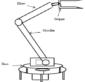
manipulator with a view to improving its operational velocity and accuracy for pick-and-place tasks.[5] The configuration of robot arm in this journal is similar to articulated robot arm which has three revolute joints and irregular workspace .The advantages of articulated robot arm are higher reach from base, useful in continuous path generation, applied to welding operation and reaching the congested small openings without interference. The rest of journal is presented as Section (II) explains Methods using in research and Section (III) show Analytical calculation. After that Section (IV) build system block diagram and next Sections are testing experimental results and observation. Finally, Section (VIII) presents the conclusion of this journal.
II.
M
ETHOD USING IN RESEARCHRobot kinematics method is the study of the motion (kinematics) of robots. In a kinematic analysis, the positions of all the links are calculated without considering the forces that cause this motion. In the kinematic analysis of manipulator position, there are two separate problems to solve: direct kinematics and inverse kinematics. Robot kinematics is the study of the motion of robotic mechanisms. Since the performance of specific manipulator tasks is achieved through the movement of the manipulator linkages, kinematics is the fundamental importance in robot design and control. A kinematic equation provides the relationship between the joint displacement and the resulting of end effector position and orientation. The problem of finding the end-effector position and orientation for a given set of joint displacements is referred to as the forward kinematics problem. That is, the forward kinematics problem allows one to specify in a unique manner the relationship between the (n x 1) joint vector θ. Normally; the forward Kinematic equation can be obtained from the spatial geometry of the manipulator or by solving certain matrix algebraic equations. [4] The more increase the number of degrees of freedom (n), the more complex kinematic equation becomes. Hence, the required amount of computation to compute the position of end-effectors can become quite large. Direct kinematics is for solving the forward transformation equations to find the location of the gripper in terms of the angles and displacements between the links.
58
transformation equations to find the relationships between the links of the manipulator from the location of the gripper in space.
Figure 1: Structure of articulated robot arm design
Forward Kinematic Inverse Kinematic Input Angles output Angles Position of Gripper Link Parameters
Figure 2; Block diagram of kinematic methods
Figure2 shows the operation of kinematic control methods. So we need robot arm design to define the link parameters of robot arm.
III. Analytical calculation of research
Figure 3; Link parameters of articulated robot manipulator
Table 1: link parameters used in calculated design
θi = rotation angles of each joints
di = distance along Z axis
αi= twisted angle between successive joints
ai = twisted length between successive joints
After assigning all link parameters of robot arm, table 1 can
construct. The link lengths as shown in Fig. 2 are L1 = 6cm, L2
= 12 cm, and L 3 = 21.5cm.
(i) Forward Transformation Matrices
Once the table1 is ready, the transformation matrices are easy to find. Generally, the matrix of transformation can be established from the relation between successive frame i to i+1.
Rotation and translation of arm matrix is iAi+1=H(z,θi).
Htran(0,0,di). Htran(ai,0,0).H(x,αi)
i
Ai+1=
1 0 0 0 cos sin 0 sin sin cos cos cos sin cos cos sin sin cos cos i i i i i i i i i i i i i i i i d a a
And then, the individual transformation matrices for i =1, 2 and 3 can be easily obtained. Thereafter, the complete
transformation 1H4 is found from:
1
H4 = 1 A2 2 A3 3 A4
Upon the determination of, 1H4 we can find the global
coordinates of the end effector. The tip point of the arm is at
the origin of frame 3 (Fig. 3), i.e. it is at [0 0 0 1]T . So, its
position in the global frame becomes:
1
H4 = 1
H4 [0 0 0 1]
T
= [dx dy dz 1]T
Analytically from kinematic method, position of the gripper will obtain
dx =cos(θ1)((L3(cos(θ2+θ3))+L2cos(θ2)) (1)
dy=sin(θ1)((L3(cos(θ2+θ3))+L2cos(θ2)) (2)
dz=L1+L3(sin(θ2+θ3))+L2sin(θ2) (3)
(ii) Inverse kinematic transformation
We end up with a set of three nonlinear equations with three unknowns. Solving these equations algebraically, known as the inverse kinematics, requires that we need to know the joint
variables (θ1, θ2 , θ3 ) for a given griper position (dx, dy, dz).
We get from equations (1) to (3), by dividing, squaring, adding and using some trigonometric formulas:
θ1= tan
-1
(dy/dx)
θ2=cos
-1
[(cosθ1dx+sinθ1dy)(a3cosθ3+a2)–a3
sinθ3(d1+dz) ∕ (a3cosθ3+a2)
2
+a2
2sin(θ
3 ) 2
]
θ3=cos
-1
[(cosθ0dx+sinθ0dy)
2
+(d0+dz)
2 –(a1 2 +a2 2 )] 2a2a3
Link i di αi θi ai cos(αi) sin(αi)
1 d1 90 θ1 0 0 1
2 0 0 θ2 d2 1 0
59
Table 2: analytical calculation result of robot arm
IV.
S
YSTEM BLOCK DIAGRAMThis research uses dual-switched power supply as a source power. It can be used the source of power to both microcontroller and servo motors. Metal detector is used for sorting system .Microcontroller is used to generate the pulse to drive the servo motors. Servo motors are used as actuators for robot arm’s joints.
The controller unit:
This is the most importance of the robot system, because it performs all vital calculation of kinematic analysis. The controller unit used in this research is on Atmega328 microcontroller and has 6 analog inputs, 14 digital input/output pins (6 of which can be used as PWM outputs). The unit receives signals (field information) from the sensors (such as metal sensor and other object sensor) and then processes it based on the already-programmed software in its memory. Actually, a pin (configured as an input pin) on the microcontroller is connected to the sensor conditioning circuit, and the microcontroller responds depending on whether this pin is HIGH or LOW. When the pin is LOW, it means there is absence of an object, and the microcontroller maintains the robot at its home position, but when the pin is HIGH, it means there is presence of an object, and the microcontroller uses a pulse width modulated signal to control the joint servo motors to drive the robot to an appropriate location (the object position in this case) in the workspace.
Microcontroller Power
supply
Metal detector
servo
servo
servo
servo
servo
servo
Fig 4: System block diagram of research
The actuating unit:
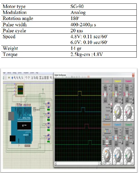
The actuators that are being implemented for the joint operation are servomotors. Because the robot is a revolute manipulator, it means all the joint variables are angle rotations, and therefore, the servomotors are very suitable. Conventional RC servo motors consist of 4 primary parts: a DC motor, a gearbox/system, a potentiometer, and a control circuit. The servomotor is controlled by a pulse width modulated signal (control signal) from the controller unit through its control wire. Since there are two types of servos with different specifications in the arm robot, the results obtained from the simulation on Proteus differ in terms of pulse width, angle and servo motor behavior. According to Table3 and Table4, the simulation considers the rotation angle with respect to the generated pulses with the pulse width ranges from 600μs to 2400μs for Tower-Pro SG-5010, and from 400 μs to 2400 μs for Tower-Pro SG-90 servo.
Table3; specification of SG-5010 servo motor
Table 4; specification of Tower pro SG-90 servo motor
Figure 5; SG-5010 servo PWM simulation by using proteus
60
In this simulation, all servo angles are 90◦ command. So, all
pulses width is 1.5 ms.
Metal detector;
Metal detector is used to detect the object is metal or not. When the object is metal, signal is sent to controller to pick up the robot arm. If the object is not metal, the robot arm is not operated the pick and place operation. In this research Metal detector is used for sorting system.
V.
F
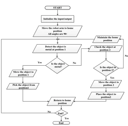
LOWC
HART OF RESEARCHInitialize the input/output START
Place the object to position2
Yes No
Move the robot arm to home position All angles are 90◦
Detect the object is metal at position 1
End? No
Is the object metal? Move the object to
position 1
Pick the object from position1
Maintain the home position
Check the object at position 2
Return to home position
Is the object in position 2?
Move the object to position 2
End Yes
No
Yes
FIGURE 6;FLOW CHART OF PICK AND PLACE ARTICULATED ROBOT ARM
VI.
POSITION TRACKING OF ROBOT ARM EXPERIMENTALLYAccording to flow diagram, home position of robot arm is assumed at dx=0cm,dy=21.5cm and dz=12cm .After that position 1 is at dx=-18cm ,dy=-18cm and dz=4cm.And then, let position 2 to be at dx= 18cm,dy=18cm and dz=4cm respectively. Original object position is set at position 1 and the final object position is set at position 2.
Figure 7; testing the robot arm at home position (all servo angles are 90◦ applied)
Figure 8; experimental testing the robot arm to reach at position 1
Robot arm to reach at position 1, inverse kinematic method is used. Distance of position 1 is applied to inverse kinematic
equation, the angles of servo motors (θ1=45◦, θ2=130◦, θ3=80◦)
is obtained. Other positions are also calculated as above description. The result angles are applied to servo motors that are connected to robot arm joints by using Arduino software.
Figure9; experimental testing of pick up object condition
61
After testing the robot arm ,there is little error occurred .The position of X, Y and Z coordinate are not equally similar to the calculated result from inverse kinematic method.
Error = ((calculated distance-experimental distance)
/calculated distance)*100%
For example, Let dx=dy=18.6cm and dz=4cm are applied to
inverse kinematic equations. The output angles θ1 = 45
◦
,
θ2=130
◦, θ 3 =80
◦
are obtained. After applying these angles to servo motors of robot arm, there is a different between the calculated result and the experimental out distance dz=0.1cm at Z coordinate and dx and dy are 0.6 cm different between the calculated result and the experimental result.
Table 5; Error calculation of experimental testing
VII.
D
ISCUSSIONKinematic control methods are useful for robotic system. In this journal forward and reverse kinematic methods has been fully explained and calculated with mathematically .From the result of this, articulated robot arm has been tested by Arduino Software with experimentally. When testing the robot arm for pick up and place operation, there is little error occurs. The occurrence of this error is because of the limitation of selected servo motors and some mechanism structure of robot arm. Whenever, the maximum rotating angle of the chosen servo
motors cannot exactly rotate 180◦.
VIII.
C
ONCLUSIONSThe inverse kinematic analysis of 3-DOF Robot is investigated. The mathematical model is prepared and solved for angles of joints. The calculated result and the testing experimental result are absolutely the same. This articulated robot arm is fully tested the operation of pick and place object at the research group centre of our university. This journal
considers the hardware, software and mathematical
calculation parts and have been discussed and tested in the practically. As the future of advanced robot arm, it can be designed to get an optimum grip on the desired object, it is recommended that a pressure sensor be incorporated on one of the end-effector’s fingers. Moreover, a camera and a computer, which has image processing capability, can be used to know locations of the object (instead of the pre-programmed positions operated in this research).
Acknowledgment
The author wishes to acknowledge especially to Dr.Myint Thein, Rector of Mandalay Technological University, for his guidance, help and sharing fruitful ideas. The author is deeply grateful to Dr.Hla Myo Tun, Associate Professor and Head,
Department of Electronic Engineering, Mandalay
Technological University for permitting all necessary electronic components has been used from lab centre. The author also wishes to U Zaw Min Min Htun, Lecturer, Department of
Electronic Engineering, Mandalay Technological University, accomplished guidance, his willingness to share his idea and, helpful suggestions and for his patience, continuous supervision and encouragement during the period of this paper.
R
EFERENCES[1] Jolly Shah, S.S.Rattan, B.C.Nakra,‖End-Effector
Position Analysis Using Forward Kinematics for 5DOF Pravak Robot Arm‖, International Journal of Robotics and Automation (IJRA),Vol. 2, No. 3, September 2013.
[2] Sanjay L., Shweta P., ―Position Control of Pick and
Place Robotic Arm‖, International Conference on Engineering Innovation and Technology, Nagpur, 1st July, 2012.
[3] Binbin L., Yimin S., Gang D., Tao S., Yang Q.,
―Dimensional Synthesis of a Planar Parallel Manipulator for Pick-and-Place Operations Based on Rigid-Body Dynamics‖, Intelligent Robotics and Applications/Lecture Notes in Computer Science, Springer, Vol. 7506, pp. 261-270, 2012.
[4] Altuzarraa O., Şandru B., Pinto Ch., and Petuya V.,
―A Symmetric Parallel Schönflies-Motion
Manipulator for Pick-and-Place Operations‖,
Robotica, Vol. 29, Issue 06, October 2011, pp. 853-862.
[5] Bin L., Yunjiang L., and Zexiang L., ―Kinematics and
Optimal Design of a Novel 3-DoF Parallel Manipulator for Pick-and-Place Applications’’, International Journal of Mechatronics and Automation, Vol.3, No.3, pp. 181 – 190, 2013.
[6] Ayokunle A.Awelewa, Samuel O. Majekodunmi, Isaac
A. Samuel, ‖Development of a Prototype Robot Manipulator for Industrial Pick-and-Place Operations‖, October 2013 IJENS
[7] Mohammad D. Abdul Hakeem, ―Design and
Comparative Assessment of State Feedback
Controllers for Position Control of 8692 DC Servomotor‖, Published by August 2015 in MECS.
[8] Jolly Shah, End-Effector Position Analysis Using