Flexural Behaviour of Uni-Directional Kenaf
Composites Using Experimental and Simulation
Methods
B.M. Yassin
a, R. Zulkifli
a,b,c, W.R.W. Daud
a, S. Abdullah
b,c aFuel Cell Institute, National University of Malaysia (UKM) bDepartment of Mechanical and Materials Engineering, Faculty of Engineering and Environment Built, Universiti Kebangsaan Malaysia (UKM)
cCentre for Automotive Research, Faculty of Engineering and Environment Built, Universiti Kebangsaan Malaysia (UKM)
Abstract-- The use of natural fibres as reinforcement materials in composites has increased significantly due to the various advantages they offer. This paper focuses on the flexural characteristics of kenaf/polyester composites that have a uni-directional fibre orientation. The scope of this research is based on the use of kenaf fibres as reinforcement materials. The reason for the selection of kenaf fibres is because they are biodegradable and allow for the ease of availability as kenaf is cultivated locally. The specimens used in the test are in the cylindrical shape with 200 mm length and 10 mm diameter. The composite specimens are prepared using a pultrusion method with uni-directional long kenaf fibres as reinforcement and polyester resin as the matrix. The specimens are tested using ASTM D790-71 standard at four different temperatures of 27C, 60C, 100C and 160C. 2 different cross-head speed used, 2mm/min and 10mm/min each. Parameters measured in these studies are stress vs. strain, displacement vs. time and displacement vs. temperature. The research findings show that the failure patterns and deformations when compared between numerical analysis and experimental works are practically the same but with minor discrepancies in the values obtained due to different surroundings. The results also reveal that the percentage between the fibres and matrixes plays a vital role in the quality. As the ratio of fibres increases, the ultimate tensile strength of the composites also escalates together with its brittleness. The failure mode and deformation observed from the experimental data have shown that kenaf/polyester composites have good energy absorption capability at room temperature of 27°C, where the strength decreases as the temperature rises.
Index Term-- Kenaf fibres, uni-directional orientation, pultrusion process, polymer matrix composites, mechanical properties
INTRODUCTION
In Malaysia, a government body known as Lembaga Kenaf dan Tembakau Negara (LKTN) was set up to control the development and commercialisation of kenaf-based products to diminish reliance on tobacco as a source of income for farmers [1]. Various efforts have been made to identify the diverse uses of kenaf, for example, in the automotive industry. In line with fast-paced technology in the field of composites, kenaf/polyester has the potential to become one of the materials that can be used in this industry, especially for vehicle trimming and finishing parts. The trend these days is to utilise composites during fabrications as inside or outside of
car parts like the door trim, dashboard or bumper. By doing in-depth research, new materials of the highest quality and values are able to be produced, and choosing the correct material will not only decrease the risk of serious damage to the driver and passengers, but will also have a significant impact like weight reduction and improvement in the performance of the vehicle [2].
It is well known that the fuel efficiency of any vehicle directly corresponds with the load conveyed by the vehicle. Therefore, experts from all around the world are searching for any potential materials that are light in weight, dependable and savvy, yet without compromising on the safety of the automotives. Development in mechanical innovation has opened up the prospect for the use of composite materials in manufacturing practices. With light weight and the capability to be mass delivered in the form of strands or powder, an impressive future can be predicted for these plants to be popularised in different types of utilisation.
Hence, such fibre laminated composite materials find applications in many fields, such as being incorporated in the hollow structures of vehicles because of their high specific strength, modulus and high damping capability. In comparison with metal-based materials, these composite materials have good yield strength, except those known for their brittleness. The natural fibre composites themselves have many types of failure mode, where one such example is brittle collapse [3]. The cylindrical shape of uni-directional composites with fibre reinforced polymer (FRP) belongs to the laminated group although it is round in shape. The use of FRP pultruded tubes can be seen extensively in the automotive industry due to their properties which collapse in a progressive and controlled manner. The result is a high rate of energy absorption when vehicles collide [4].
composite materials with features like the impact of geometry on the outline of material properties [7] [8] [9]. In composites, there are many failure modes involved, i.e., deformation, development of micro-cracking and fibre breakage.
Materials Preparation
In this study, the examined specimens are made of kenaf yarn and polyester blend. Material selection was based on the materials’ ability to mutually support each other in the fabrication of a lightweight and strong composite material. As reported by other researchers, kenaf fibres have a proven record as reinforcement for the polyester matrix [10]. Even though polyester has decent elongation properties, it is weak in elasticity and Young's modulus. It is inverse to kenaf which has good elasticity and Young’s modulus but not in elongation. In accordance with the goal to deliver a green composite, the most significant quality is conceivable by applying more natural fibres. The tensile strength is directly proportional to the fraction of the fibres’ volume. It has also been highlighted that the orientation of fibres used during material fabrication affects the strength of the composites [11]. These effects of orientation occur not just on long fibres,
but also for short fibres (Fu & Lauke, 1996). Kenaf fibres that have been used are twisted to form the yarn. With those qualities, it should be able to give strength due to having two essential features: long in length and twisted fibres.
The kenaf fibres that are twisted have extra strength as they have good contact between the fibres, causing them to hold each other strongly. Strengthening among themselves also contributes to an improvement in the strength of the overall composites that are manufactured. The main focus of this study concentrates on the rate of the flexural behaviour of the material. Results can be utilised to recognise the most ideal use of this composite material, such as for a vehicle part. 70:30 proportional was chosen for the purpose of understanding how far the usage rate of the natural fibre can be maximised and yet still maintain a high strength. This ratio refers to the 70% material made from kenaf yarn. Studies done by other researchers are retrieved as a comparison, whereby the available results gained from other research are in the ratio of 0%, 10%, 20%, 30%, 40% and 50% [12]. The sets of values stated refer to the mixture made from natural fibres compared to the matrix.
(a) (b)
Fig. 1. (a) Kenaf yarn roll (b) Containers containing unsaturated polyester (UP) and its hardener, (MEKP).
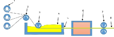
The unsaturated polyester resin (UP), REVERSOL P-9771, is designed for the pultrusion of the profile sections. Unsaturated polyester is in the form of a transparent viscous liquid at room temperature, which is similar to the hardener used to cure it, Methyl Ethyl Ketone Peroxide (MEKP). It is one of the types of polymers that solidify thermally (thermosets) which turns it into a solid state when the MEKP is added. Proportion of the blend is 100:1 between the UP and the hardener. It is essential to conduct the blend readiness at a warm temperature of around 20°C in order to have the resin cured effectively. The sample preparation method is using the pultrusion process, where the initial step is by manoeuvring the kenaf yarn into a polymer-topped compartment that is filled with the UP. It will hang down for two minutes before being pulled through a cylindrical mould that has been heated at 120°C. The kenaf
yarn together with the polyester will be cured when passing through the
heated mould. A round profile with a diameter of 10mm utilising the pultrusion procedure is the finished item known as a Kenaf/Polyester (KP) composite. The cured composites are later cut into lengths of 200mm each for testing purposes. The samples were prepared using facilities at Innovative Pultrusion Sdn Bhd.
The flows and processes involved during the process shown in Fig. 2:
EXPERIMENTAL METHODS
The experiment work was done on a universal testing machine: flexural testing machine Instron 5567. The
specimens were tested with the parameters as shown in Table I
Table I
Parameters used for testing the specimens Sample size Ø10 x
200mm
Ø10 x 200mm
Ø10 x 200mm
Ø10 x 200mm
Cross head speed
2mm/min 2mm/min 2mm/min 2mm/min
Temp 27°C 60°C 100°C 160°C
Quantity 3 3 3 3
Name KP_27C_1 KP_27C_2 KP_27C_3
KP_60C_4 KP_60C_5 KP_60C_6
KP_27C_7 KP_27C_8 KP_27C_9
KP_27C_10 KP_27C_11 KP_27C_12
Sample size Ø10 x 200mm
Ø10 x 200mm
Ø10 x 200mm
Ø10 x 200mm
Cross head speed
10mm/min 10mm/min 10mm/min 10mm/min
Temp 27°C 60°C 100°C 160°C
Quantity 3 3 3 3
Name KP_27C_1a KP_27C_2a KP_27C_3a
KP_60C_4a KP_60C_5a KP_60C_6a
KP_27C_7a KP_27C_8a KP_27C_9a
KP_27C_10a KP_27C_11a KP_27C_12a
The study was conducted using the 3-point bending method as suggested in the standard ASTM D790 71. A total of 24 specimens were tested with all samples created from the untreated kenaf yarn blended with the unsaturated polyester. Two distinct velocities of 2mm/min and
10mm/min were applied together with 3 tons cross-head as the load.
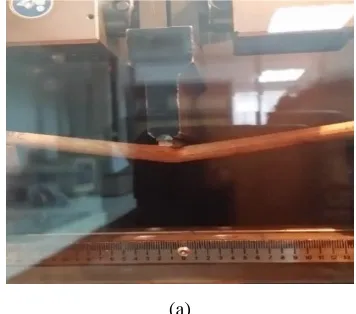
(a) (b)
Fig. 3.Failure of specimens during the test using the 3-point bending method. (a) The KP fails under load (b) The load is removed from the specimen
Material properties have a big impact on even a simple tension and/or flexural measurements [13]. Thus, the material closest to the surface (top and bottom) plays a vital role as it will be the most affected from the stress imposed.
(a) (b)
Fig. 4. (a) Fibre pullout on tested sampleof kenaf polyester (b) SEM image shows that the polymer does not bind well with the fibres, causing pullout. The scanned image in Fig. 4(b) projects a relatively rough
surface of the fibre. Polyester has hydrophobic properties while kenaf belongs to the hydrophilic group. This combination resulted in the need for rough surfaces in order to increase the grip between both materials. This will give good contact between the surface of the kenaf yarn and the polyester. Good contact is very crucial as it will help in
increasing the friction between surfaces [14, 15]. As highlighted, polyester has low viscosity which consequently explains the phenomena in Fig. 5(b) where voids appear. It may have been caused by the curing temperature where it is cured before having been fully spread in the composite. Since it has low viscosity, it also stops air, which prevents the kenaf yarn from escaping.
(a) (b)
Fig. 5. (a) image shows that the polymer does not hold well with the fibrous wall with impregnations voids appearing (b) High density of fibres can be seen from the cross-section of KP as shown in the picture
In a flexural test, the total bending deflection is a combination of a bending deflection and a shear deflection as shown in Eq. (1):
Eq. (1)
Eq. (2)
The value for each raving, linear density, density and area is 0.11631, 600, 1.27 and 78.5 respectively. Thermal experiments conducted in another study reported that for kenaf fibres, tensile strength decreases when kept at 180°C
for 60 minutes, but if kept at the same temperature for 30 minutes, the strength is as good as no heat treatment at all [16].
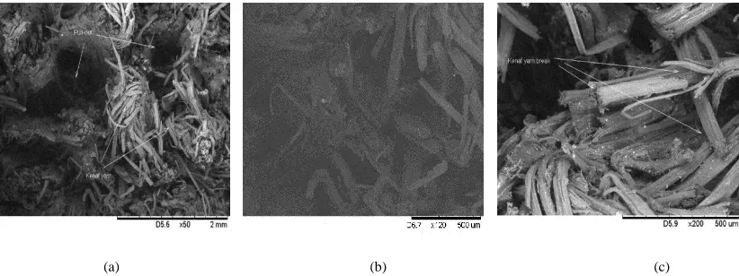
(a) (b) (c)
Fig. 5. (a) SEM micrographic image showing pullouts (b) SEM micrograph showing kenaf yarn that is separated from polyester (c) SEM micrograph showing breaks and cuts that expose the primary and secondary wall of the fibre
The fact that such large cavities can be seen from this pullout stems from the lack of a good absorption of the polymer by the kenaf yarn. With 70% of the total composite made of kenaf, as it travels through the mould, it squeezes the polyester far out of its way while aligning takes place in the mould. In addition, inconsistency in the kenaf yarn diameters also contributes to the minimum contact surface, resulting in the inability of the kenaf yarn to move deep into the composite before being treated.
RESULTS AND DISCUSSION
The analysis has shown that kenaf/polyester (KP) composites can take impact up to 145MPa average, as documented using the 3 tonne cross head load-cell setup with a load speed of 10mm/min at the temperature of 27°C. Evaluation of similar samples tested at the same temperature, but with the variance of the load speed set at 2mm/min,
illustrated a gain in value of 138MPa average. As shown in Fig’s, even though the composite has the capability to absorb force up to 145MPa at room temperature, it does not deform much which is indicating a good advantage for the usage of components that require toughness where the temperature is not extreme. It can be further noted that as the temperature rises, the KP starts losing its toughness.
Fig. 8. Stress-strain graph plotted based on average values of all samples tested on different cross-head speeds and temperatures
Fig. 9. Stress-Strain graph of specimens tested at 27°C with speeds of 2mm/min (KP_1, KP_2 & KP_3) and 10mm/min (KP_1a, KP_2a & KP_3a)
In addition, according to Fig. 9, detailed samples tested at the same temperature and load speed (27°C, 2mm/min) indicate only a little displacement, which is 1.8%. As the temperature rises, we can see the matrixes beginning to lose their quality. This scenario can be explained as the effect of thermal stress
towards the curing thermoset [17]. The effect of the temperature towards absolute values (storage modulus) has been reviewed and discussed by other researchers, and their findings have suggested that variation in the modulus is the result of incorporating fibres.
Fig. 10. Stress-Strain graphs tested at 60°C with speeds of 2mm/min (KP_4, KP_5 & KP_6) and 10mm/min (KP_4a, KP_5a & KP_6a) 0
20 40 60 80 100 120 140 160
0 2 4 6 8
St
re
ss
(
M
pa
)
Strain (%)
Stress vs Strain
KP_27C_2
KP_27C_10
KP_60C_2
KP_60C_10
KP_100C_2
KP_100C_10
KP_160C_2
KP_160C_10
0 20 40 60 80 100 120 140 160
0 1 2 3
St
res
s
(M
p
a)
Strain (%)
Stress vs Strain of Kenaf-Polyester (KP) at 27°C
KP_1
KP_2
KP_3
KP_1a
KP_2a
KP_3a
0 20 40 60 80 100 120
0 1 2 3 4
St
res
s
(M
p
a)
Strain (%)
Stress vs Strain of Kenaf Polyester (KP) at 60ºC
KP_4
KP_5
KP_6
KP_4a
KP_5a
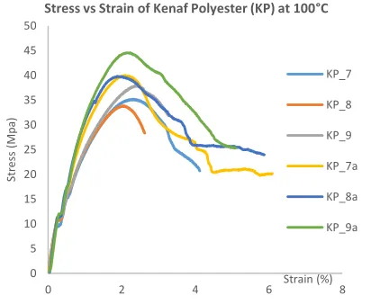
Fig. 11. Stress-Strain graphs tested at 100°C with speeds of 2mm/min (KP_7, KP_8 & KP_9) and 10mm/min (KP_7a, KP_8a & KP_9a)
Fig. 12. Stress-Strain graphs tested at 160°C with speeds of 2mm/min (KP_10, KP_11 & KP_12) and 10mm/min (KP_10a, KP_11a & KP_12a)
KP_27C_2, KP_60C_2, KP_100C_2 & KP_160C_2 represent 2mm/min load speed while KP_27C_10, KP_60C_10, KP_100C_10 & KP_160C_10 represent 10mm/min load speed. The data displays that the kenaf polyester composite can take up to 350N/mm2 when the pressure is applied at the speed of 2mm/min at 27°C as show in Fig. 4.
Low energy absorption is due to sufficient time for the reinforcers to break their bonding with the matrix. This also contributes to failure with a lower rate during the 2mm/min test. A deformation happens as the load is applied; filling the void increases the failure, therefore resulting in a low load being measured [18].
As the temperature increases, the failure form starts to decline to lower values. During 60°C, both specimens fail when the load reached 253N/mm2 and 199.9N/mm2. These situations show that heat does give effect to the kenaf polyester composite. Osman et al. reported that the ratio between the hardener and the unsaturated polyester does have impact on the strength of the material.
Without proper curing time, the strength of the material is jeopardised. The longer the time is taken to harden gives enough time for the molecules to bind and rest properly, resulting in better strength. Since there are untreated kenaf fibres, the lignins that coat the surface of the kenaf fibres contribute to the low binding strength between the polymer and the fibre and the polymer becomes loose due to the effect of the increase in the temperature.
4. CONCLUSION
Kenaf has the ability to be used as a good composite material. It has helped increase the rate of absorption of impact in the kenaf/polyester composite. It is a suitable material as a reinforcer for polymer. Further studies should be conducted in order to improve the production of composite materials and polymer-based research projects without going through the treatment process that uses other chemicals in producing products that are more environmentally friendly.
It is clear from the results that the untreated kenaf/polyester composite cannot be used at high temperature areas as it will weaken the material and cause failure in terms of usage. 0
5 10 15 20 25 30 35 40 45 50
0 2 4 6 8
St
res
s
(M
p
a)
Strain (%)
Stress vs Strain of Kenaf Polyester (KP) at 100°C
KP_7
KP_8
KP_9
KP_7a
KP_8a
KP_9a
0 5 10 15 20 25 30
-2 0 2 4 6 8
St
res
s
(M
Pa
)
Strain (%)
Stress vs Strain of Kenaf Polyester (KP) at 160°C
KP_10
KP_11
KP_12
KP_10a
KP_11a
For high performance practice, KFRP should be used on the components which is not exposed to high temperatures. The study by Saheb et al. had to clarify the effect of heats on lignocellulosic materials where it deteriorated in line with the increase in temperature [19]. Hence the importance of this research can be seen in the efforts to understand the result of temperature on this composite which is very helpful for automotive designers in deciding materials for components[20].
ACKNOWLEDGEMENTS
Financial support for this research work was provided from the research grant code: LRGS/2013/UKM-UKM/TP/01. The authors gratefully acknowledge the time spent by the staff members of the Mechanics of Materials Engineering Laboratory, Faculty of Engineering and Built Environment, Universiti Kebangsaan Malaysia (UKM) to materialise the testing. In addition, the authors would like to thank the staff members of Cell Fuel Institute, UKM for their guidance and help.
REFERENCES
[1] A. R. Rozyanty, M. Y. Nur Firdaus, T. Z. Liew, and N. F. M. Yunus, “Kenaf-Unsaturated Polyester Composite: The Effect of Different Retting Process of Kenaf Bast Fiber on the Mechanical Properties,” Mater. Sci. Forum, vol. 819, pp. 256–261, 2015. [2] R. A. Eshkoor, A. U. Ude, A. B. Sulong, R. Zulkifli, A. K. Ariffin,
and C. H. Azhari, “Energy absorption and load carrying capability of woven natural silk epoxy - Triggered composite tubes,” Compos. Part B Eng., vol. 77, pp. 10–18, 2015.
[3] M. Feizbahr, M. Jamshidi, and C. Kok Keong, “Review on Various Types and Failures of Fibre Reinforcement Polymer,” Middle-East J. Sci. Res., vol. 13, no. 10, pp. 1312–1318, 2013.
[4] H. Ghasemnejad, B. R. K. Blackman, H. Hadavinia, and B. Sudall, “Experimental studies on fracture characterisation and energy absorption of GFRP composite box structures,” Compos. Struct., vol. 88, no. 2, pp. 253–261, 2009.
[5] Z. Yu and X. Xu, Failure analysis cases of components of automotive and locomotive engines. Elsevier, 2016.
[6] A. Baldan, “Adhesively-bonded joints and repairs in metallic alloys, polymers and composite materials: Adhesives, adhesion theories and surface pretreatment,” J. Mater. Sci., vol. 39, no. 1, pp. 1–49, 2004.
[7] P. Rahul-Kumar, A. Jagota, S. J. Bennison, S. Saigal, and S. Muralidhar, “Polymer interfacial fracture simulations using cohesive elements,” Acta Mater., vol. 47, no. 15–16, pp. 4161– 4169, Nov. 1999.
[8] R. A. Shenoi and G. L. Hawkins, “Influence of material and geometry variations on the behaviour of bonded tee connections in FRP ships,” Composites, vol. 23, no. 5, pp. 335–345, Sep. 1992. [9] W. J. Cantwell and J. Morton, “The impact resistance of composite
materials — a review,” Composites, vol. 22, no. 5, pp. 347–362, Sep. 1991.
[10] S. H. Aziz and M. P. Ansell, “The effect of alkalization and fibre alignment on the mechanical and thermal properties of kenaf and hemp bast fibre composites: Part 1 - polyester resin matrix,” Compos. Sci. Technol., vol. 64, no. 9, pp. 1219–1230, 2004. [11] A. N. Netravali, “Ramie Fiber Reinforced Natural Plastics,” in
Natural Fibers, Plastics and Composites, F. T. Wallenberger and N. E. Weston, Eds. Springer US, 2004, p. pp 321–343.
[12] H. N.A.K., H. M.W., J. M.Y., B. M.A.R., I. M., and A. M., “Tensile Behaviour of Kenaf Fiber Reinforced Polymer Composites,” J. Teknol., vol. 69, no. 3, pp. 11–15, 2014.
[13] P. Wambua, J. Ivens, and I. Verpoest, “Natural fibres: Can they replace glass in fibre reinforced plastics?,” Compos. Sci. Technol., vol. 63, no. 9, pp. 1259–1264, 2003.
[14] R. Zulkifli and C.H. Azhari, “Interfacial Treatment of Multi-Layer
Woven Silk/Epoxy Composites”, International Review of Mechanical Engineering, vol. 4, no. 1, pp.1–6, 2010.
[15] R. Zulkifli, C.H. Azhari, M.J. Ghazali, A.R. Ismail and A.B. Sulong. “Interlaminar Fracture Toughness of Multi-Layer Woven Silk/Epoxy Composites Treated with Coupling Agent”, European Journal of Scientific Research, vol. 27, no. 3, pp. 454–462, 2009. [16] S. Ochi, “Mechanical properties of kenaf fibers and kenaf/PLA
composites,” Mech. Mater., vol. 40, no. 4–5, pp. 446–452, 2008. [17] H. Akil, A. Akram, M. Mazuki, S. Safiee, Z. Arifin, M. Ishak, and
A. A. Bakar, “Study on Dynamic Mechanical Properties of Pultruded Kenaf Fiber Reinforced Composites,” Engineering, pp. 7–10.
[18] R. Yahaya, S. M. Sapuan, M. Jawaid, Z. Leman, and E. S. Zainudin, “Effect of fibre orientations on the mechanical properties of kenaf– aramid hybrid composites for spall-liner application,” Def. Technol., vol. 12, no. 1, pp. 52–58, 2015.
[19] D. N. Saheb, J. P. Jog, D. Nabi Saheb, and J. P. Jog, “Natural Fiber Polymer Composites : A Review,” Adv. Polym. Technol., vol. 18, no. 4, pp. 351–363, 1999.