Theoretical and Experimental Investigation on a
Compact Multi-band Frequency Selective
Surface
Priyanka Deb Sinha
Department of Engineering and Technological Studies University of Kalyani, Kalyani, Nadia, West Bengal, India.
Riya Bhattacharyya
Department of Engineering and Technological Studies University of Kalyani, Kalyani, Nadia, West Bengal, India.
Dr. Partha Pratim Sarkar
Department of Engineering and Technological Studies University of Kalyani, Kalyani, Nadia, West Bengal, India
Abstract- This paper deals with the simulated and measured investigation of a single layered Frequency Selective Surface (FSS) with three resonating frequencies obtained at 3.12 GHz, 8.3 GHz and 10.4 GHz. The frequency ratio obtained for the second and first resonating frequency is 2.66 whereas the frequency ratio obtained for the third and second one is 1.25. The designed FSS can be operated in S band, C band and X band of frequencies. Also the compactness obtained for the proposed FSS is 91.91%. The designed FSS is simulated using MOM based software Ansoft Designer V2.2 and the simulated result is verified experimentally using standard microwave test bench. A good agreement is obtained between the simulated and the experimental results.
Keywords – Compactness, Frequency Selective Surface, Multiple frequency operation.
I. INTRODUCTION
zero. Thus this type of FSS can be treated as band-pass filter [1-3]. Patch type FSSs have been used in millimeter wave imaging [4], in cellular systems [5], for electromagnetic interference (EMI) reduction [6] and in indoor wireless propagation [7]. Aperture types FSSs find applications in radio astronomy [8], solar power generation [9], energy saving [10], millimeter/sub-millimeter wave transceivers [11-12], and microwave lenses [13]. To meet the increasing demand of multi functional wireless communication devices, more complicated FSS designs capable of operating in multiple frequency bands are being proposed [14-18]. Several research works have been proposed on FSSs from the past few decades [19-24]. In this paper simple slots are introduced on the patch of the FSS to obtain multi-frequency operation and compactness.
II. DESIGNOFTHEFSS
The design of the conventional patch type FSS is done by using a two dimensional array of a square shaped patch of dimension 20 mm × 20 mm. The metallic patches are present on one side of the dielectric substrate and the metal used here is copper. The copper coating present on the other side of the dielectric slab is completely removed.
Fig. 1. Unit cell of the conventional FSS. Fig. 2. Unit cell of Proposed FSS Structure.
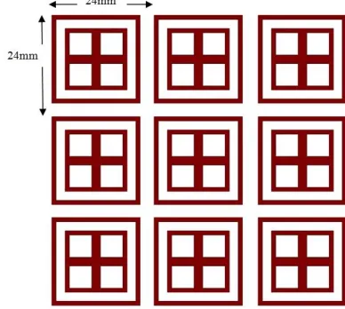
The periodicity is 24 mm in both horizontal and vertical directions. Acrylic sheet is used as the dielectric substrate in designing the proposed FSS. It has a dielectric constant of 2.8 and the height of the dielectric is taken to be 1.6mm. The unit cell of the conventional patch type FSS is shown in Fig 1.
The conventional patch was replaced by a modified design. The modified design contains two concentric patches. The inner patch is a square shaped patch having four square shaped slots, each of dimension 5mm X 5mm. The outer patch is a square ring of 1mm surrounding the inner square patch. The structure of the unit cell of the designed FSS is shown is Fig 2, along with all other dimensions. The periodicity in both the horizontal and vertical direction is shown in Fig 3.
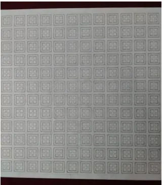
Generally two methods are applied to miniaturize the size of the FSS. The first method is by using dielectric substrate having high permittivity. The other method is by increasing the effective electrical length of the metallic patch. The first method provides greater losses and thus they are less efficient. So it is avoided. They also yield relatively smaller bandwidths [25-26]. Therefore the second method is used in this paper to obtain high compactness of the FSS. This is done by introducing specific slots on the patch of the FSS which in turn meanders the patch surface current. As a result multiple resonating frequencies are obtained along with compactness of the FSS. The fabricated Frequency Selective Surface is shown in Fig4.
III. RESULTS
Using MOM based Ansoft Designer Software the simulated results are obtained and plotted in Fig 5. The results are also tabulated in Table 1.
Transmission test for the proposed FSS is done in the microwave laboratory using microwave test bench. Two horn antennas (one for transmission and the other one for reception) were used. The designed FSS were mounted on a wooden frame stand and placed between the two horn antennas. The transmitting horn antenna was connected to Agilent Signal Generator, and the receiving horn antenna was connected to Power meter. Measurements using different horn antennas in the frequency range of 2-11 GHz are done with an interval of 0.1GHz for the incident waves with angles zero degree to the normal. The signal generated by the signal generator is blocked at all
frequencies except at 3.12 GHz, 8.3 GHz and 10.4 GHz. This was verified by the readings obtained in the power meter. A graph of normalized transmitted electric field versus frequency was plotted in the same Fig 5 for obtaining a comparison with the simulated result.
After performing the experiment it was observed that the designed FSS had 3 resonating frequencies at 3.12 GHz, 8.3 GHz and 10.4 GHz with the corresponding percentage bandwidth of 17.62%, 27.46% and 7.69% respectively.
IV. CONCLUSION
From the obtained simulated and measured data, it is observed that the designed FSS can be operated in three multiple frequencies. Also the percentage bandwidth obtained for each of the operating frequencies for the designed FSS is good. In comparison to the conventional patch type FSS to that of the designed FSS, the resonating frequency decreases from 10.97 GHz to 3.12 GHz (considering first resonant frequency). In the reference FSS when no
Fig 5: Transmission characteristics of the designed FSS.
modification was done, the resonating frequency was 10.97 GHz. To obtain the resonating frequency at 3.12 GHz, it would require the area of the patch to be 1687.12 mm2 approximately. The area of the reference patch is calculated to be 136.39 mm2 approximately. Therefore the size reduction is calculated as [(1687.12 -136.39)/ 1687.12]*100, which results in a compactness of 91.91%.
REFERENCES:
1. Ben A. Munk, Frequency selective surface Theory and design( New York, John Wiley & Sons Inc, 2000).
2. B. Munk, Finite Antenna Arrays and FSS(New York, Wiley & Sons, 2003).
3. T. K. Wu, Frequency Selective Surface and grid array(New York, John Wiley & Sons, 1995).
4. Z. Shen, N. Ito, E. Sakata, C. W. Domier, Y. Liang, N. C. Luhmann Jr., and A. Mase, “Frequency selective surface notch filter for use in a millimeter wave imaging system,” in Proc. IEEE Antennas and Propagation Society Int. Symp., Albuquerque, NM, Jul. 9–14, 2006, pp. 4191–4194.
5. D. H. Kim, J. H. Yeo, and J. I. Choi, “Compact spatial triple-band-stop filter for cellular/PCS/IMT-2000 systems,” ETRI J., vol. 30, no. 5, pp. 735–737, Oct. 2008.
6. C. N. Chiu, Y. C. Chang, H. C. Hsieh, and C. H. Chen, “Suppression of spurious emissions from a spiral inductor through the use of a frequency selective surface,” IEEE Trans. Electromagn. Compat., vol. 52, no. 1, pp.56–63,Feb.2010.
7. M. Raspopoulos and S. Stavrou, “Frequency selective buildings through frequency selective surfaces,” IEEE Trans. Antennas Propag., vol. 59, no.8,pp. 2998–3005,Aug.2011.
8. I. Yoshihisa and T. Takano, “Frequency selective surfaces for radio astronomy,” Expe. Astron., vol. 2, pp. 123–136, Sep. 1991.
9. W. E. Horne, M. D. Morgan,W. P. Horne, and V. S. Sundaram, “Frequency selective surface bandpass filters applied to thermo photovoltaic generators,” in Proc.Thermo photovoltaic Generation of Electricity 6th Conf. on Thermo photovoltaic Generation of Electricity, 2004, vol. 738,pp. 189–197.
10. G. I. Kiani, L. G. Olsson, A. Karlsson, K. P. Esselle, andM. Nilsson, “Cross-dipole bandpass frequency selective surface for energy-saving glass used in buildings,” IEEE Trans. Antennas Propag., vol. 59, no.2, pp. 520–525, Feb. 2011.
11. R. Cahill et al., “Frequency selective surfaces for millimetre and submillimetre wave quasi optical demultiplexing,” Int. J. Infrared Milli. Waves, vol. 14, pp. 1769–1788, 1993.
12. T. L. A. Rhys, “Quasi-optical diplexer with a frequency-selective surface for a millimeter-wave receiver,” Radiophys. Quant. Electron., vol. 46, no. 8–9, pp. 713–716, Aug. 2003.
13. M. Al-Joumayly and N. Behdad, “Wideband planar microwave lenses using sub-wavelength spatial phase shifters,” IEEE Trans. Antennas Propag., vol.59, no. 12, pp. 4542–4552, Dec. 2011.
14. J. Huang, T. K. Wu, and S. W. Lee, “Tri-band FSS with circular ring elements,” IEEE Trans. Antennas Propag., vol. 42, no. 2, pp. 166–175,Feb. 1994.
15. M. Salehi and N. Behdad, “A second-order dual X-/Ka-band frequency selective surface,” IEEE Microw. Wireless Compon. Lett., vol. 18, no.12, pp.785–787,Dec.2008.
16. T. K. Wu and S. W. Lee, “Multi-band FSS with multi-ring patch elements,” IEEE Trans. Antennas Propag., vol. 42, no. 11, pp. 1484–1490,Nov. 1994.
17. J. Romeu and Y. Rahmat-Samii, “Fractal FSS: A novel dual-band frequency selective surface,” IEEE Trans. Antennas Propag., vol. 48, no.7,pp.1097–1105,Jul.2000.
19. Kamal Sarabandi, Fellow, IEEE, and Nader Behdad, Member, IEEE, “A Frequency Selective Surface With Miniaturized Elements,” IEEE TRANSACTIONS ON ANTENNAS AND PROPAGATION, VOL. 55, NO. 5, MAY 2007.
20. Antonio Lazaro, Member, IEEE, Angel Ramos, David Girbau, Member, IEEE, and Ramon Villarino, “A Novel UWB RFID Tag Using Active Frequency Selective Surface,” IEEE TRANSACTIONS ON ANTENNAS AND PROPAGATION, VOL. 61, NO. 3, MARCH 2013.
21. Liang Zhang, Member, IEEE, QunWu, Senior Member, IEEE, and Tayeb A. Denidni, Senior Member, IEEE, “Electronically Radiation Pattern Steerable Antennas Using Active Frequency Selective Surfaces,” IEEE TRANSACTIONS ON ANTENNAS AND PROPAGATION, VOL. 61, NO. 12, DECEMBER 2013.
22. Peng Wu, Fan Bai, Quan Xue, Fellow, IEEE, Xun Liu, Member, IEEE, and S. Y. Ron Hui, Fellow, IEEE, “Use of Frequency-Selective Surface for Suppressing Radio-Frequency Interference from Wireless Charging Pads,” IEEE TRANSACTIONS ON INDUSTRIAL ELECTRONICS, VOL. 61, NO. 8, AUGUST 2014.
23. Irfan Sohail Syed, Student Member, IEEE, Yogesh Ranga, Member, IEEE, Ladislau Matekovits, Senior Member, IEEE, Karu P. Esselle, Senior Member, IEEE, and Stuart G. Hay, Senior Member, IEEE “A Single-Layer Frequency-Selective Surface for Ultrawideband Electromagnetic Shielding,” IEEE TRANSACTIONS ON ELECTROMAGNETIC COMPATIBILITY, VOL. 56, NO. 6, DECEMBER 2014.
24. S. N. Azemi, K. Ghorbani, and W. S. T. Rowe, “Angularly Stable Frequency Selective Surface With Miniaturized Unit Cell,” IEEE MICROWAVE AND WIRELESS COMPONENTS LETTERS, VOL. 25, NO. 7, JULY 2015.
25. Arup Ray, Manisha Kahar, Sushanta Biswas, Debasree Sarkar, Partha Pratim Sarkar, “A Dual Tuned Complementary Structure Frequency Selective Surface for WLAN Applications,” Journal of Microwaves, Optoelectronics and Electromagnetic Applications, Vol. 11, No. 1, June 2012.