Angular-Stability Low-Profile Miniaturized Frequency Selective
Surface Based on Complementary Structure
Wenxing Li and Yuanyuan Li*
Abstract—A new architecture for a low-profile miniaturized-element frequency selective surface based on complementary structure capable of providing a high angular stable performance is proposed. The proposed FSS is composed of an array of convoluted cross dipoles and its complementary slots pattern that is separated by a thin dielectric substrate. An equivalent circuit model for this FSS is presented to provide a deep insight into the mechanism of reducing the unit size by shifting and lengthening the dipoles. With the use of this method, the FSS unit cell size has been significantly reduced to only 0.0085λ×0.0085λ, and the thickness is 0.000093λ, whereλrepresents the resonant wavelength in free space. Moreover, the proposed FSS achieves good stability in the scope of incidence angles of 86 degrees for both TE and TM polarizations. Besides, the length of the dipoles can tune the resonant frequency.
1. INTRODUCTION
Frequency selective surface (FSS) has been intensively investigated for their wide range of application in military and commercially areas over the past few decades. FSS is a two-dimensional periodic structure composed of periodically arranged metallic patches or aperture elements which are etched on the surface of the dielectric substrate. It can act as a spatial filter which has a selective effect on the incident angle, polarization and frequency of electromagnetic wave [1, 2]. Frequency selective surface has been widely used as radar radome [3], antenna reflector [4, 5], polarization converter [6], microwave absorber [7], etc. In practical applications, it is difficult to arrange sufficient number of elements in the limited region and make them act as an infinite FSS [8, 9]. Therefore, miniaturized FSS is proposed and investigated extensively. Methods of several types have been implemented to design miniaturized FSS in the past, of which using convoluted and interwoven technique [10–12], loading via technique [13, 14], capacitive surface and inductive surface coupling technique [15, 16], and loading lumped elements technique [17] are the prominent. The principle of them is to increase the equivalent inductance and capacitance of the FSS. It is a flexible and obvious method to reduce the unit size by loading lumped elements. Liu et al. proposed an FSS loaded with inductance and capacitance and has a dimension of 0.028λ×0.028λ, whereλis the wavelength in free space at resonant frequency [17]. However, this method requires bulk lumped elements, which increases the difficulty of fabrication. In recent years, designing a miniaturized FSS without loading has attracted more and more attentions. In [10], a miniaturized FSS realized by symmetrically bending the edges of square loop aperture element has been proposed. The unit size is 0.0538λ ×0.0538λ. In [13], a 2.5-dimension miniaturized FSS consisting of a planar meandering line and a vertical via-based meandering line has been proposed with a 0.033λ×0.033λ dimension. In [12], an interwoven and convoluted dipoles were used to achieve a miniaturized FSS, and the element size is 0.0094λ×0.0094λ. In [16], Lin et al. proposed a miniaturized FSS based on the coupling method, and the unit cell dimension is 0.0094λ×0.0094λ. One common feature of the aforementioned
Received 26 April 2017, Accepted 2 June 2017, Scheduled 11 June 2017 * Corresponding author: Yuanyuan Li ([email protected]).
2. DESIGN OF COMPLEMENTARY MINIATURIZED FSS 2.1. Topology of FSS and Working Principle
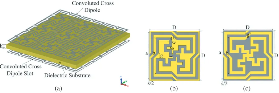
Figure 1(a) shows a 3-D view of the complementary miniaturized FSS, consisting of two metal layers separated by a dielectric substrate with a thickness ofh. The main challenge in design of the miniaturized FSS is decreasing the unit cell in dimension for reducing the sensitivity of the polarization and the incident angle. With the view to overcoming it, the unit cell is designed symmetrically in x and y directions. Hence, the period of the topology in x and y directions is equal (Dx =Dy =D), and the unit cell on the top layer uses a convoluted cross dipole structure, while the unit cell on the bottom layer is the complementary slot of the unit cell on the top layer.
(a) (b) (c)
Figure 1. Topology of the proposed miniaturized FSS. (a) 3-D view of the FSS. (b) Unit cell on top layer. (c) Unit cell on bottom layer D= 5.7 mm, a= 5.4 mm, b = 4.2 mm, w = 0.3 mm, s = 0.3 mm,
s0 = 0.3 mm, L= 0.6 mm,g= 0.6 mm, h= 0.508 mm.
(a) (b)
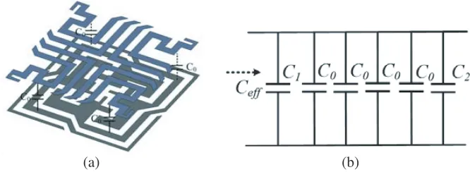
Figure 2. (a) Equivalent circuit model of the proposed FSS. (b) Simplified equivalent circuit model of (a).
resonant frequencies are calculated as
f0 =
1
2πL1(C1+C2)
(1)
fz = 1 2π√L2C2
(2)
The dielectric substrate, sandwiched between two metal layers, is equivalent to a short transmission line whose length is h. Its impedance isZT =Z0/√εr, whereZ0 is the wave impedance in free space and
εr the relative permittivity of the dielectric substrate.
2.2. Simulation and Experimental Verification
The miniaturized FSS has been fabricated and measured. The prototype has two metal layers fabricated on two sides of a 0.508 mm thick RO4350B substrate whose permittivity is 3.48. It contains 50×50 cells in a 285 mm×285 mm region. Fig. 3 shows photographs of FSS and the measurement setup. The measurement results started from 1 GHz is because the horn antennas for testing operate at 1–8 GHz.
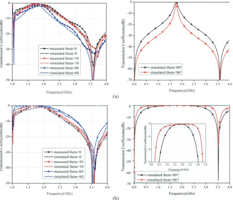
Figure 4 compares the measurement and simulated results calculated by CST-MWS and equivalent circuit model. As illustrated, the FSS transmits the signal at 1.75 GHz, while reflecting the unnecessary signal at 3.51 GHz, and the simulation results are in good agreement with the measurement ones. The fractional bandwidth is 45%. The unit size is 0.041λ×0.041λ, and the thickness is 0.0037λ, where λ is the resonate wavelength in free space. We reach the conclusion that this FSS demonstrates a good performance of miniaturization and low profile. The frequency response of the FSS at different incident angles has also been examined.
(a) (b)
Figure 4. Simulated and measurement results of miniaturized FSS.
Figure 5 shows the measurement results as well as the simulated ones in comparison. The frequency response is extremely stable under different angles for both TE and TM polarizations when the incident angle is changed from 0◦ to 60◦. The resonant frequency shows fair stability even when the incident angle was larger than 80 degrees for TE polarization. For TM polarization, however, the deviations of resonant frequency are 5.13% and 26.5% when the incident angles are 80 and 86 degrees, respectively. It is observed that the bandwidth decreases with the increase of incident angle for TE polarization, whereas the TM polarization is the opposite. This observed changes can be illustrated by the variation of wave impedance [18]. In the case of TE polarization, the wave impedance (ZT E =Z0/cosθ) increases with the increase of the incident angle, and then the quality factor of the filter’s resonator decreases, which causes the reduction of the bandwidth of resonator. For TM polarization, the wave impedance (ZT M = Z0cosθ) decreases with the increase of the incident angle, which causes the decline of the quality factor of filter’s resonator, and the bandwidth of the FSS is broadened.
3. MODIFIED MINIATURIZED FSS
It is known that reducing the unit size is to increase the value of the equivalent inductance or capacitance of the FSS element. In this section, investigations on reducing the unit size and improving the angular stability are carried out. First, the unit size is notably decreased by increasing the capacitance of the FSS. Then the equivalent inductance is increased by lengthening the convoluted cross dipoles.
3.1. Miniaturized FSS Based on Shifting Method
The methods of increasing the equivalent capacitance include reducing the distance between slots in each layer, increasing the dielectric constant and reducing the substrate thickness. Besides the aforementioned methods, the capacitance also lies on the overlapping area between the two metal layers. In our design, we use the shifting method to make an offset between the top and bottom metal layers to increase the equivalent capacitance. The top layer is shifted byD/2 alongxandysimultaneously as shown in Fig. 6. Figure 7 shows the modified structure and its equivalent circuit to the capacitive structure. We observe that the four overlapping parts between the top and bottom metal layers form parallel plate capacitors of C0. It may be approximated by the following equation [15]:
C0=
ε0εeffA
h (3)
(a)
(b)
Figure 5. Measured and simulated transmission coefficients of FSS for oblique incident angles. (a) TE polarization. (b) TM polarization.
(a) (b)
(a) (b)
Figure 7. (a) The capacitive structure. (b) The equivalent circuit model of the capacitive structure.
the equivalent capacitance can be calculated by the following formula:
Ceff=C1+4C0+C2 (4)
Therefore, the unit size is decreased by increasing the equivalent capacitance which is proportional to the overlapping area and is inversely proportional to the thickness of the dielectric substrate. The frequency response is calculated by the CST-MWS. The relative dielectric constant is 4.4, and the thickness is 0.101 mm. The resonant frequency of the modified FSS is reduced to 0.66 GHz, and the unit size is significantly miniaturized to 0.013λ×0.013λ.
3.2. Miniaturized FSS Based on Lengthening the Dipoles
To further reduce the unit size of the FSS, the convoluted cross dipoles presented in Fig. 6 are lengthened to increase the equivalent inductance of the FSS as shown in Fig. 8. P is the dimension of the modified FSS.
(a) (b)
Figure 8. Topology of modified FSS based lengthening the convoluted cross dipoles. P = 9.3 mm. (a) Top layer. (b) Bottom layer.
Figure 9. Comparison of transmission coefficients of the modified FSS and the FSS presented in Fig. 1.
as presented in Fig. 10. In addition, the transmission properties of angular stability and polarization independence are summarized in Table 1. As observed, the response is stable when the incident angles change from 0◦ to 86◦ for both TE and TM polarizations with a deviation of merely 0.7% for TM polarization when the incident angle is 86◦. Comparisons of the element size and maximum incident angle between the modified FSS and the previous works are presented in Table 2. From Table 2, it
Table 1. Data for TE and TM incident angles.
Incident angle TE Polarization TM Polarization f01(GHz) f01deviation(%) f01(GHz) f01deviation(%)
0◦ 0.276 0 0.276 0
30◦ 0.276 0 0.276 0
60◦ 0.276 0 0.276 0
80◦ 0.276 0 0.276 0
86◦ 0.276 0 0.276 0.7
Table 2. Results comparison to other miniaturized FSS structures.
εr element Unit size (λ) Thickness (λ) Incident angle Center frequency (GHz)
2.2 Ref. [14] 0.067 0.0013 80◦ 3.33
This FSS 0.012 0.0004 86◦ 0.38
3 Ref. [12] 0.018 0.0048 60◦ 2.9
This FSS 0.01 0.00011 86◦ 0.33
4.4 Ref. [13] 0.0094 0.000047 75◦ 0.14
This FSS 0.0085 0.000093 86◦ 0.276
5 Ref. [11] 0.0538 0.0088 60◦ 1.647
This FSS 0.008 0.00027 86◦ 0.68
10.2 Ref. [15] 0.0094 0.00056 60◦ 0.188
(a) (b)
Figure 10. Transmission coefficients of the modified FSS under different incident angles. (a) TE polarization. (b) TM polarization.
is seen that the design exhibits more miniaturized performance and produces a better angular stable response.
3.3. Sensitivity of the Response to Dielectric Constant and Substrate Thickness
According to the working principle of the modified FSS, the parameters of the dielectric substrate directly affect the frequency response of the FSS. Fig. 11 shows the results of the modified FSS with respect to the thickness of the dielectric substrate. The resonant frequency increases with the thickness. This is because the thickness is equivalent to the space of a parallel plate capacitor. It is inversely proportional to equivalent capacitance.
Figure 11. Transmission coefficients of the modified FSS for different thickness.
4. CONCLUSIONS
In this paper, a novel, low-profile and miniaturized frequency selective surface with a high angular stability based on complementary structure is proposed. A method of shifting top layer and lengthening the dipoles to reduce the element size is presented and validated. The FSS has a much better miniaturization and low profile performance than other elements proposed in previous literatures with the unit size of 0.0085λ×0.0085λ and thickness of 0.000093λ. The FSS exhibits excellent angular stability for both TE and TM polarizations up to 86◦. In addition, the element size is able to be further reduced by applying this method.
ACKNOWLEDGMENT
This paper was supported by the National Defense “973” Basic Research Development Program of China (No. 6131380101). This paper was also supported by Pre-research Fund of the 12th Five-Year Plan (No. 4010403020102 and No. 4010103020103) and the Fundamental Research Funds for the Central Universities (Nos. HEUCFD1433 and HEUCF1508).
REFERENCES
1. Ben, A., Frequency Selective Surface — Theory and Design, Vol. 319, 315, A Wiley-Interscience Publication, 2000.
2. Farahat, A. E., K. F. A. Hussein, and N. M. El-Minyawi, “Spatial filters for linearly polarized antennas using free standing frequency selective surface,” Progress In Electromagnetics Research M, Vol. 2, 167–188, 2008.
3. Chen, Q. and Y. Fu, “A planar stealthy antenna radome using absorptive frequency selective surface,” Microwave and Optical Technology Letters, Vol. 56, 1788–1792, 2014.
4. Edalati, A. and K. Sarabandi, “Reflectarray antenna based on grounded loop-wire miniaturised-element frequency selective surfaces,”IET Microwaves, Antennas& Propagation, Vol. 8, 973–979, 2014.
5. Chatterjee, A. and S. Parui, “Performance enhancement of a dual-band monopole antenna by using a frequency selective surface-based corner reflector,” IEEE Transactions on Antennas and Propagation, 1, 2016.
6. Gangwar, D., S. Das, R. L. Yadava, and B. K. Kanaujia, “Circularly polarized inverted stacked high gain antenna with frequency selective surface,” Microwave and Optical Technology Letters, Vol. 58, 732–740, 2016.
7. Wang, H., P. Kong, W. Cheng, W. Bao, X. Yu, L. Miao, et al., “Broadband tunability of polarization-insensitive absorber based on frequency selective surface,” Sci. Rep., Vol. 6, 23081, 2016.
8. Oraizi, H. and M. Afsahi, “Design of metamaterial multilayer structures as frequency selective surfaces,”Progress In Electromagnetics Research C, Vol. 6, 115–126, 2009.
9. Guo, C., H.-J. Sun, and X. Lv, “A novel dualband frequency selective surface with periodic cell perturbation,” Progress In Electromagnetics Research B, Vol. 9, 137–149, 2008.
10. Li, W., C. Wang, Y. Zhang, and Y. Li, “A miniaturized frequency selective surface based on square loop aperture element,” International Journal of Antennas and Propagation, Vol. 2014, 1–6, 2014. 11. Zhao, P.-C., Z.-Y. Zong, W. Wu, and D.-G. Fang, “A convoluted structure for miniaturized frequency selective surface and its equivalent circuit for optimization design,” IEEE Transactions on Antennas and Propagation, Vol. 64, 2963–2970, 2016.
with miniaturized unit cell,”IEEE Microwave and Wireless Components Letters, Vol. 25, 454–456, Jul. 2015.
16. Lin, B.-Q., S.-H. Zhao, X.-Y. Da, Y.-W. Fang, J.-J. Ma, and Z.-H. Zhu, “Design of a miniaturized-element frequency selective surface,”Microwave and Optical Technology Letters, Vol. 57, 2572–2576, 2015.
17. H. L. Liu, K. L. Ford, and R. J. Langley, “Design methodology for a miniaturized frequency selective surface using lumped reactive components,” IEEE Transactions on Antennas and Propagation, Vol. 57, 2732–2738, 2009.
18. Al-Joumayly, M. A. and N. Behdad, “Low-profile, highly-selective, dual-band frequency selective surfaces with closely spaced bands of operation,”IEEE Transactions on Antennas and Propagation, Vol. 58, 4042–4050, 2010.