EMR Integration Technical Application Overview – 357729-003
Contents Purpose...1 Objectives ...1 Application Overview ...2 Component Definitions...3Follow-up Information Retrieval ...4
Patient Record Dismissal...6
Follow-up Information Transfer..10
Patient Record Sign-off...12
Appendix A – HL7 Message Structures ...16
LATITUDE HL7 Message Specification...16
GE CPO HL7 Message Specification...25
Appendix B – LATITUDE Terms ...26
Appendix C – Patient Matching ...40
Purpose
This document provides a high-level description of the
technical architecture and data flows of the Boston Scientific
LATITUDE Patient Management System to GE Healthcare
Centricity
®Physician Office (CPO) (formerly Logician)
integration solution.
CPO is GE Healthcare’s outpatient electronic medical
record (EMR) system. LATITUDE is Boston Scientific’s
remote patient monitoring system. Personnel that are
responsible for administering CPO at a clinic can use this
document to understand the technical components of the
integration solution. A base understanding of the system
components, processes, and associated terminology can
help administrators support the system and troubleshoot
problems.
Objectives
The objective of the LATITUDE EMR Integration software is
to provide a quick and easy mechanism for downloading
implanted cardiac device follow-up summary data from
LATITUDE into the EMR and also to provide quick access
from the EMR back into LATITUDE to review detailed
cardiac device data for a patient.
Your existing Logician / CPO technical and user
documentation should be used to understand the
proper use of the Logician / CPO product.
EMR Integration Technical Application Overview – 357729-003
Application Overview
The following diagram is a model that depicts the major technology components and data flows of
the integration solution.
Technology components are defined in “Table 1 - Component Definitions” below.
There are four major data flow processes that are described in subsequent sections of this
document.
−
Follow-up information retrieval
−
Patient record dismissal
−
Follow-up information transfer
EMR Integration Technical Application Overview – 357729-003
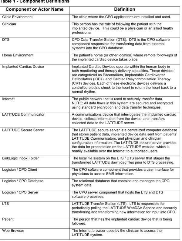
Component Definitions
Table 1 - Component Definitions
Component or Actor Name
Definition
Clinic Environment The clinic where the CPO applications are installed and used. Clinician This person has the role of following the patient with the
implanted device. This could be a physician or an allied health professional.
DTS CPO Data Transfer Station (DTS). DTS is the CPO software component responsible for transferring data from external systems into the CPO database.
Home Environment The patient’s home (or other location) where remote follow-ups of the implanted cardiac device takes place.
Implanted Cardiac Device Implanted Cardiac Devices operate within the human body in both monitoring and therapy delivery capacities. These devices are categorized as Pacemakers, Implantable Cardioverter Defibrillators (ICDs), and Cardiac Resynchronization Therapy (CRT) devices. Each of these electronic devices delivers a controlled electric shock to the heart to return the heart back to a normal rhythm.
Internet The public network that is used to securely transfer data. NOTE: All data flows in this system are secured and encrypted using standard encryption and data transfer techniques. LATITUDE Communicator A communications device that interrogates the implanted cardiac
device, collects information from the device, and transfers collected data to the LATITUDE server.
LATITUDE Secure Server The LATITUDE secure server is a centralized computer database that stores patient data, implanted device data sent from patients’ LATITUDE Communicators, and physician and clinician
configuration information. The LATITUDE secure server provides the data for presentation on the LATITUDE website, which is readily available over the Internet to authorized users. LinkLogic Inbox Folder The local file system on the LTS / DTS server that stages the
transformed LATITUDE download files prior to DTS processing. Logician / CPO Client The CPO software component that provides a user interface for
physicians to access EMR information.
Logician / CPO Database The relational database that contains and manages the CPO system data.
Logician / CPO Server The CPO server component that hosts the LTS and DTS software processes.
LTS LATITUDE Transfer Station (LTS). LTS is responsible for periodically polling the LATITUDE WebDAV Service and securely transferring and transforming new information for input into CPO. Patient The person that has the implanted cardiac device that is being
followed.
Web Browser The Internet browser used by the clinician to access the LATITUDE system.
EMR Integration Technical Application Overview – 357729-003
Follow-up Information Retrieval
LATITUDE retrieves information from the Home Environment
LATITUDE - GE Logician / CPO Integration
Interrogation
Clinic EnvironmentBoston Scientific Home Environment
LATITUDE Communicator
Logician / CPO Database
LATITUDE Secure Server Internet Patient with Implanted Cardiac Device
Logician / CPO Server DTS LTS LinkLogic Inbox Folder Logician / CPO Client Web Browser Clinician
EMR Integration Technical Application Overview – 357729-003
Assumptions:
−
Patient has implanted cardiac device.
−
LATITUDE Communicator has been installed and configured.
1 At defined periods the LATITUDE Communicator interrogates the implanted
device.
2 The implanted device sends data, concerning device and patient status, to the
LATITUDE Communicator.
3 The LATITUDE Communicator processes the device data and utilizes a phone
line to establish a secured Internet network connection to the LATITUDE server.
4 The LATITUDE Communicator securely transfers the device data to the
LATITUDE server.
5 The LATITUDE secure server processes the device data and stores it into the
patient’s record in the LATITUDE database.
EMR Integration Technical Application Overview – 357729-003
Patient Record Dismissal
Patient records on the Patient for Review screen are reviewed by a clinician or clinicians
and subsequently dismissed.
Clinic Environment
Boston Scientific Home Environment
LATITUDE Communicator
Logician / CPO Database
LATITUDE Secure Server Internet Patient with Implanted Cardiac Device
Logician / CPO Server DTS LTS LinkLogic Inbox Folder Logician / CPO Client Web Browser Clinician
LATITUDE - GE Logician / CPO Integration
Dismissal
EMR Integration Technical Application Overview – 357729-003
1 The clinician logs into the LATITUDE web application…
EMR Integration Technical Application Overview – 357729-003
3 The clinician selects a patient follow-up record and reviews patient data on the
clinically appropriate LATITUDE screens.
4 The clinician dismisses the patient, triggering the creation of a LATITUDE HL7
device summary message, which is stored in the LATITUDE secure server.
Patient is selected using check box.
Patients are dismissed by clicking on the Dismiss patient icon. This function can also be performed from the Patient Detail screens.
EMR Integration Technical Application Overview – 357729-003
There may be circumstances where a download of a patient follow-up record
needs to be rerun. LATITUDE has a mechanism for rerunning a patient follow-up
record download. By clicking on the menu options Patient Utilities / EMR Log a
page will be displayed that contains a function to place already downloaded
Patient follow-up records into the EMR outbox. This will cause LTS to see and
transfer the HL7 file again. The data will be identical to the initial download.
Select patient record using the check box.
Move previously downloaded records into the EMR Outbox by clicking on icon
EMR Integration Technical Application Overview – 357729-003
Follow-up Information Transfer
EMR Integration Technical Application Overview – 357729-003
Assumptions:
−
The LATITUDE HL7 Device Summary message files have been written to
storage on the LATITUDE secure server that is accessible from the clinic.
Each file includes summary follow-up information and a direct URL link to the
corresponding patient detail summary screen in LATITUDE.
1 LTS running on the CPO server in the clinic monitors the clinic’s
LATITUDE-hosted web folder for new HL7 files by polling the LATITUDE secure server on a
periodic basis using a secure WebDAV protocol. The frequency of polling is
specified in the LTS configuration file
LTS.
INIwhich should be set to 60 seconds.
2 When LTS polling finds a new HL7 file on the LATITUDE secure server, it
transfers the file using a secure WebDAV protocol.
3 LTS performs the processing needed to generate appropriate files for importing
into the EMR. LTS creates two CPO HL7 files for every LATITUDE HL7 file.
One file is a lab report (HL7 ORU message) and has an extension
HR. The other
file is an image file (HL7 MDM message) and has an extension
HT. Once the
HL7 file is transferred, the LATITUDE secure server automatically removes
access, but retains the data for retransmission purposes. If specified in
LTS.
INI, a
copy of the HL7 file will be saved on the Logician CPO server.
NOTE
: Details
concerning the content of the HL7 files are contained in Appendix A – HL7
Message Structures of this document.
4 LTS writes the CPO HL7 files to the LinkLogic Inbox Folder.
5 DTS imports the data from the LinkLogic inbox folder into the CPO Database.
The HL7 ORU message file is first imported into a CPO lab report document.
Next, the HL7 MDM message file, which contains the specified URL, is imported
and attached to the lab report.
6 During the import process lab codes, document types, physician information, and
patient information are cross-referenced and mapped from LATITUDE to CPO.
See Appendix C for more information on Patient Matching.
7 DTS writes the device follow-up information to the CPO Database.
8 DTS changes the extensions of processed files in the LinkLogic Inbox Folder
EMR Integration Technical Application Overview – 357729-003
Patient Record Sign-off
EMR Integration Technical Application Overview – 357729-003
1 The clinician logs into the CPO client and observes new patient documents.
2 The clinician opens up the patient’s device follow-up document and reviews the
information.
The clinician performs other clinical processes that may include linking to the
LATITUDE web application for further follow-up data review. The clinician will
Clicking on paperclip icon automatically links to LATITUDE Patient Detail pages
EMR Integration Technical Application Overview – 357729-003
not need to re-enter username and password if already logged into LATITUDE,
and the IE browser is configured to open a new session in an existing window.
EMR Integration Technical Application Overview – 357729-003
EMR Integration Technical Application Overview – 357729-003
Appendix A – HL7 Message Structures
The LATITUDE to EMR Integration solution relies on HL7 structured messages for the
transferring of information. The out-of-box solution provides mappings and transformations of
HL7 messages to internal GE CPO data structures. This section provides details concerning the
structure and semantics of the HL7 messages for those doing custom work.
It is assumed that readers of this section are familiar with HL7 2.x terminology,
specification syntax, data types, message structures and semantics for ORU messages.
For more information concerning HL7 messaging visit HL7’s web site at
www.hl7.org
.
The LATITUDE to GE Healthcare EMR Integration solution consists of two sets of HL7
messages.
−
HL7 messages generated by LATITUDE
−
HL7 messages created by the LTS component for consumption by GE CPO
LATITUDE HL7 Message Specification
The LATITUDE application generates one HL7 message for each remote device follow-up.
These messages are retrieved by LTS for use within GE CPO. See the Follow-up Information
Transfer section of this document for details concerning this process.
The LATITUDE HL7 file is structured according to the HL7 2.3.1 Observation Result Unsolicited
(ORU) message type, which provides for the transmission of new observation information about
patients in the form of a lab report document.
LATITUDE’s ORU message will contain useful follow-up summary data, including information
from LATITUDE’s Quick Notes report plus leads information and device counters. The message
consists of the following segment structures.
Message Structure
Segment
Description
Usage
MSH Message Header The MSH segment contains information about the Sender and Receiver of the message, the type of the message, a time stamp, etc., and is the first segment in each ORU message.
PID Patient Identification The PID segment contains demographic information about the patient such as name, id codes, zip code, and so on. This information is used for patient matching.
[{ NTE }] Notes and comments THE NTE segment contains alerts and events that have occurred for a particular patient.
PV1 Patient Visit The PV1 (Patient Visit) segment contains information regarding the patient's encounter, such as location assigned, referring doctor, etc. { --- grouping BEGIN
EMR Integration Technical Application Overview – 357729-003
MSH Segment
ELEMENT NAME SEQ SUB
SEQ
DT LEN USAGE CARD TBL# ITEM # Fixed Example Value
Field Separator 1 ST 1 R [1..1] 00001 Y | Encoding Characters 2 ST 4 R [1..1] 00002 Y ^~\& Sending Application 3 HD 180 R [1..1] 00003 Y LATITUDE Sending Facility 4 HD 180 R [1..1] 00004 Y Boston
Scientific Receiving Facility 6 HD 180 RE [0..1] 00006 Clinic Name Date/Time Of
Message
7 TS 26 R [1..1] 00007 2006051015005 7+0000 Message Type 9 MSG 15 R [1..1] 00009
message code 1 ID 3 R [1..1] 0076 Y ORU trigger event 2 ID 3 R [1..1] 0003 Y R01 Message Control ID 10 ST 20 R [1..1] 00010 2500144 Processing ID 11 ID 1 R [1..1] 0103 00011 P Version ID 12 ID 5 R [1..1] 0104 00012 Y 2.3.1 Accept Acknowledgement Type 15 ID 2 R [1..1] 0155 00015 Y NE Character Set 18 ID 6 R [1..1] 0211 00692 Y 8859/1
EMR Integration Technical Application Overview – 357729-003
PID Segment
ELEMENT NAME SEQ SUB
SEQ
DT LEN USAGE CARD TBL# ITEM # Fixed Example Value
Set ID – PID 1 SI 1 R [1..1] 00104 Y 1 Patient ID 2 CX 20 R [1..1] 00105 ID 1 ST 20 R [1..1] 4234793618 see NOTE 2 Patient Identifier List 3 CX 20 R [1..1] 00106 ID 1 ST 20 R [1..1] 4234793618~ abc123456 see NOTE 2 & 3 Patient Name 5 XPN 140 R [1..1] 00108
family+last name prefix
1 CM 40 R [1..1] Doe given name 2 ST 40 R [1..1] John middle initial or name 3 ST 40 RE [0..1] Jimmy suffix 4 ST 20 RE [0..1] Jr. Date/Time Of Birth 7 TS 1 RE [0..1] 00110 19271209 Sex 8 IS 1 RE [0..1] 0001 00111 M zip or postal code 5 ST 10 RE [0..1] 55408
PID NOTES
1. The PID segment contains data used for patient matching (see Appendix C – Patient
Matching)
2. Patient ID and Patient Identifier List contains a unique patient number that is
generated and maintained by LATITUDE.
3. LATITUDE allows an authorized user to enter their own patient identifier. The Patient
Identifier List may contain the user entered patient identifier as a second patient
identifier.
EMR Integration Technical Application Overview – 357729-003
NTE Segment
ELEMENT NAME SEQ SUB
SEQ
DT LEN USAGE CARD TBL# ITEM # Fixed Example Value
Set ID - NTE 1 SI 1 R [1..1] 00096 1
Source of comment 2 ID 8 R [1..1] 00097 Y LATITUDE Comment 3 FT 65536 R [1..*] 00098 See content
descriptions in NOTE 1
NTE NOTES
1. There is the potential for 4 NTE segments within each device follow-up message.
The Set ID and description for these segments will be as follows:
o
Set ID 1 – This NTE segment contains a report consisting of an array of alerts
that have occurred for a particular patient. There may be more than one alert
associated with the given patient/physician pair. The alerts are sorted such that
all red alerts appear first followed by yellow alerts. Secondary sorting within each
alert type is newest to oldest.
o
Set ID 2 – This NTE segment contains information concerning the LATITUDE
patient record dismissal. It will contain information about who performed the
dismissal and when it was performed.
o
Set ID 3 – This NTE segment contains a report consisting of an array of events
(stored episodes) that have occurred for a particular patient since the last device
follow-up. There may be more than one event associated with the given
patient/physician pair. Events are sorted newest to oldest.
o
Set ID 4 – This NTE segment contains information about the device if it is in a
fault condition. It will contain a fault warning statement and information
concerning the fallback mode.
EMR Integration Technical Application Overview – 357729-003
PV1 Segment
ELEMENT NAME SEQ SUB
SEQ
DT LEN USAGE CARD TBL# ITEM # Fixed Example
Value Set ID - PV1 1 SI 4 R [1..1] 00131 Y 1 Patient Class 2 IS 1 R [1..1] 00132 Y R Attending Doctor 7 XCN 60 RE [0..1] 00137 ID Number (ST) 1 ST 8 R [1..1] JHopkins see NOTE 1 family+last
name prefix 2 CM 40 R [1..1] Hopkins given name 3 ST 40 RE [0..1] John middle
initial or name 4 ST 1 RE [0..1] L suffix 5 ST 20 RE [0..1] Sr.
PV1 NOTES
1. Attending Doctor ID Number is the LATITUDE login name of the responsible
physician.
EMR Integration Technical Application Overview – 357729-003
OBR Segment
ELEMENT NAME SEQ SUB
SEQ
DT LEN USAGE CARD TBL# ITEM # Fixed Example Value
Set ID – OBR 1 SI 4 R [1..1] 00237 Y
1 thru 4 see NOTE 1 Filler Order Number 3 EI 22 R [1..1] 00217
entity identifier 1 ST 10 R [1..1] Unique identifier see NOTE 2 Universal Service ID 4 CE 200 R [1..1] 00238 identifier 1 ST 10 R [1..1] Boston Scientific -LastInterrogation see NOTE 1 text 2 ST 50 R [1..1] Last Interrogation see NOTE 1 Observation Date/Time # 7 TS 26 R [1..1] 00241 20060429080005+00 00 Observation End Date/Time # 8 TS 26 RE [0..1] 00242 20060429080005+00 00 Ordering Provider 16 XCN 120 RE [0..1] 00226 ID Number 1 ST 10 RE [0..1] JHopkins see NOTE 3 Placer Field 1 18 ST 2 R [1..1] 00253 Y DR see Note 4 Results Rpt/Status Chng – Date/Time + 22 TS 26 RE [0..1] 00255 20060429080005+00 00 Result Status + 25 ID 1 R [1..1] 0123 00258 Y F
OBR Notes
1. The LATITUDE ORU message supports four OBRs (Observation Reports). Each
OBR will contain multiple OBX records with context specific observations. Details
concerning the specific OBX observations are listed in the OBX Segment section of
this documentation.
CPO will initially support two flow sheet views for the LATITUDE interface – one for
the Lead Information OBR, and one for the remaining three OBRs.
The CPO flow sheet groups observation results into columns by date/time stamp of
the observation. As a result, one LATITUDE HL7 export file will be disbursed into
separate CPO flow sheet columns for each Last Interrogation, Implant, and Leads
Information OBR, plus each unique last in-office lead test date.
The four types of OBRs will have different Set IDs, and Universal Service IDs as
follows.
ORU Name Description Set ID Universal Service ID identifier
Universal Service ID text
Last
Interrogation
This OBR contains observations from the last remote
monitoring session.
1 Boston Scientific-LastInterrogation
Last
Interrogation Implant This OBR contains observations
generated at the time the PG was implanted. 2 Boston Scientific-Implant Implant Last In-Office Lead Test
This OBR contains observations from the latest in-office Lead Test.
3 Boston Scientific-LastInOffice
Lead Test: In-Office
EMR Integration Technical Application Overview – 357729-003
ORU Name Description Set ID Universal Service IDidentifier
Universal Service ID text
Lead Information
This OBR contains information about implanted leads.
4 Boston Scientific-Leads
Lead Information
2. Filler Order Number is a unique identifier generated by LATITUDE for all four OBRs.
The Filler Order Number will not change for observations that are resent.
3. Ordering Provider is the LATITUDE login name of the responsible physician.
4. Placer Field 1 is a value that CPO uses to identify the type of observation being sent.
It is always set to DR which stands for Diagnostic Report.
EMR Integration Technical Application Overview – 357729-003
OBX Segment
ELEMENT NAME SEQ SUB
SEQ
DT LEN USAGE CARD TBL# ITEM # Fixed Example Values
Set ID - OBX 1 SI 4 R [1..1] 00569 Sequential Integer starting with 1 Value Type 2 ID 2 R [1..1] 0125 00570 ST or NM or DT see NOTE 1 Observation Identifier 3 CE 80 R [1..1] 00571
identifier 1 ST 80 R [1..1] see NOTE 2 text 2 ST 256 R [1..1] see NOTE 2 name of coding
system 3 ST 20 R [1..1] Y GDT-LATITUDE Observation Value 5 -- 4000 RE [0..1] see NOTE 3
Units 6 CE 60 RE [0..1]
identifier 1 ST 20 RE [0..1] see NOTE 4 Observation Result Status 11 ID 1 R [1..1] 0085 00579 Y F Date/Time of the Observation 14 TS 26 R [0..1] 00582 20060317170000+0 006
OBX Notes
1. The value types will be ST – String, NM – Number, or DT – Date.
2. All observations are coded using LATITUDE specific terms. Specifications concerning
these terms are in Appendix B – LATITUDE Terms.
3. Observation Value is the value of the observation and will be of the type Value Type.
4. Units of the observation if applicable.
EMR Integration Technical Application Overview – 357729-003
Z Segments
ELEMENT NAME SEQ SUB
SEQ
DT LEN USAGE CARD TBL# ITEM # Fixed Example Value
Segment Type 1 ST 3 R [1..1] Y ZU1 or ZU2 see NOTE 1 Value 2 ST 40 R [1..1] URL or Report
Type see NOTE 1
Z NOTES
1. The Z Segments are customized segments used to transfer LATITUDE specific
information. The two types of Z segments used are described below.
o
ZU1 – Value contains the URL string that allows a system user to link to the
Patient Details screen.
Ex.
https://www.test.bostonscientific.com/access/physician/patientDetails?=123456789o
ZU2 – Value contains Latitude message description and version.
EMR Integration Technical Application Overview – 357729-003
GE CPO HL7 Message Specification
The LATITUDE HL7 message is transferred and transformed by the LTS component (see section
Follow-up Information Transfer for details). Refer to the GE CPO documentation for specifics
concerning the structure of the resulting HL7 ORU and MDM messages that are imported directly
into CPO.
The terms used in the LTS transformed OBX records generally remain unchanged from the
original LATITUDE HL7 message. Some conversions such as unit identifiers are performed. The
ZU1 segment is transformed into an MDM message. Refer to Appendix B – LATITUDE Terms for
detailed information concerning OBX terminology.
EMR Integr
at
ion Tech
nic
al Applicatio
n Ov
er
vi
ew
– 3577
29-00
3
26
LATITUDE
®
Patient Management
TITUDE T
erms
OBR Se Descrip tion Data Ty p e Unit CPO Fl o w Shee t Label CPO ML I Code GDT Co de Last In terr ogation Implan tThe Result Sour
ce identifies the source of
the data (e
.g., R
emote Inter
rogati
on, In-office
Lead Test, Impla
nt, etc.) T RESULTS O UR C E MLI-90638 GDT -0000 1 X X X
Device manufacturer compan
y na me T DEV_COMPAN Y MLI-80809 GDT -0000 2 X X The t ype of device T DEV_T Y PE MLI-80815 GDT -0000 3 X X
The name given
to a device b y th e manufacture r T DEVICE NAME MLI-90639 GDT -0000 4 X X X
The device mode
l name T DEVMODEL NAME MLI-90640 GDT -0000 5 X X X
The device mode
l number T GENR T MOD# MLI-10833 GDT -0000 6 X X X
The device serial number
T GENERA TSERN O MLI-25145 GDT -0000 7 X X X Implant date of t he device T DEVIMPLANTD T MLI-93614 GDT -0010 8 X X X The percent age t hat repr esents th e batter y life. N % BATT GA UGE MLI-90641 GDT -0000 8 X Represents an al ert or n
otification about the
current status of the batter y. T BATT STA T US MLI-90642 GDT -0000 9 X The batte ry volta ge measurement taken b y the implanted de vice. T V MNTR V O LTA G E MLI-93612 GDT -0001 0 X
The length of tim
e required f
or the
last high
voltage capacitor charge. This is representative of
batter y status in some implanted devices. T s CHG TIME MLI-96738 GDT -0001 1 X The date o
f last capacitor refo
rmat ion in the implanted device. T LST CAP RF RM MLI-75520 GDT -0001 2 X
EMR Integr
at
ion Tech
nic
al Applicatio
n Ov
er
vi
ew
– 3577
29-00
3
Page
27
LATITUDE
®
Patient Management
OBR Se Term N ame Descrip tion Data Ty p e Unit CPO Fl o w Shee t Label CPO ML I Code GDT Co de Last In terr ogation Implan t Counters SinceThe starting dat
e
that the counte
r values are calculated from T COU N TRSSIN C E MLI-90643 GDT -0009 7 X VF Episodes Total Ventricular Fibrillation Episo des: The number of e
pisodes in the highest tach
y
zone detected since the Counte
rs Since date T VF EPISODES MLI-90644 GDT -0001 3 X VT Episodes VT Episodes: VT Zone a rrh ythmia s detected
since the Counte
rs Since date T VT EPISODES MLI-90645 GDT -0001 4 X VT-1 Episodes VT-1 Episodes: VT-1 Z one ar rh yt hmias
detected since the Counte
rs Since date T VT1 EPISODES MLI-90646 GDT -0001 5 X Non-Sustained V entricular Episodes Total Ventricular Tach yc ardia Non -Sustained Episodes: The n umber of N on-Su stained VT
episodes detected since
the Coun ters Since date T NSVTEPISODE S MLI-90647 GDT -0001 6 X ATR Mode S w itc hes ATR Mode S w itc
hes: The numb
er
of mode
sw
itches detecte
d since the "Cou
nters Since" date T ATRMODESWC H S MLI-90648 GDT -0001 7 X AFib Episodes Atrial Fibrillati on Episodes: Atrial Fibrillation
episodes detected since the "Cou
nters Since" date T AF EPISODES MLI-90649 GDT -0001 8 X SVT Episodes Supraventricular (Atrial) Tach yc a rdia
Episodes: SVT (AT) epi
sodes det
ected since
the "Count
ers Since" date
T AT EPISODES MLI-90650 GDT -0001 9 X
Atrial Percent Paced
Right Atrial
Pacing Percent: Th
e p
ercent of
all Right atrial events detected since the Counters Since d
ate that w e re pac ed. N % RA % PACED MLI-90651 GDT -0002 0 X
EMR Integr
at
ion Tech
nic
al Applicatio
n Ov
er
vi
ew
– 3577
29-00
3
28
LATITUDE
®
Patient Management
OBR Se Descrip tion Data Ty p e Unit CPO Fl o w Shee t Label CPO ML I Code GDT Co de Last In terr ogation Implan t Right VentricularPacing Percent: The
percent of all Right ventricular events detected since the Counte
rs Since date that
w e re paced. N % RV % PACED MLI-90652 GDT -0002 1 X Left Ventricular P acing Percent: T he percent
of all left ventricu
lar events detected since
the Counte
rs Since date that
w e re paced. N % LV % PACED MLI-90653 GDT -0002 2 X The curr ent statu
s of the Right Atri
al Lead
determined b
y th
e device based on anal
ys
is
of the lead amplitude and impeda
nce. If a
value encountere
d is outside of the expected
range, its status is presented.
T RALEADSTAT U S MLI-90654 GDT -0002 3 X Right Atri al Intrin sic Amplitude (P-W ave) measured du ring
an Intrinsic Amplitude Test.
T mV RA INTR NSAMP MLI-90692 GDT -0002 4 GDT -0009 8 GDT -0010 9 X X
Right Atrial Lead
Impedance meas ured during a Lead Im pedance Test. T ohms RA PACE IMPD MLI-90693 GDT -0002 5 GDT -0009 9 GDT -0011 0 X X The curr ent statu s of the Right Ve ntricular Lead dete rmined b y the d evice based on anal ys
is of the lead amplitude and
impedance. If a value encountere
d is outside
of the expected r
ange, its status is
presented. T RVLEADSTAT U S MLI-90655 GDT -0002 6 X Right Vent ricular Intrinsic Amplitud e (R-Wave) measured during an Int rinsic Amplitude Test. T mV RV INTR NSAMP MLI-90695 GDT -0002 7 GDT -0010 1 GDT -0011 2 X X X Right Vent ricular Lead Impeda nce measured during a Lead Im pedance Test. T ohms RV PACE IMPD MLI-90696 GDT -0002 8 GDT -0010 2 GDT -0011 3 X X X
EMR Integr
at
ion Tech
nic
al Applicatio
n Ov
er
vi
ew
– 3577
29-00
3
Page
29
LATITUDE
®
Patient Management
OBR Se Term N ame Descrip tion Data Ty p e Unit CPO Fl o w Shee t Label CPO ML I Code GDT Co de Last In terr ogation Implan t LV Lead Status The curr ent status of the Left Vent
ricular Lead dete rmined b y the d evice based on anal ys
is of the lead amplitude and
impedance. If a value encountere
d is outside
of the expected r
ange, its status is
presented. T LVLEADSTATU S MLI-90656 GDT -0002 9 X LV Intrinsic Amplitude Left Ventricu lar I ntrinsic Amplitud e (R-Wave) measured du ring
an Intrinsic Amplitude Test.
T mV LV INTRNSAMP MLI-90685 GDT -0003 0 GDT -0010 4 GDT -0011 5 X X X LV Pace Impeda nce Left Ventricular L ead Impedance measured during a Lead Im pedance Test. T ohms LV PACE IMPD MLI-90658 GDT -0003 1 GDT -0010 5 GDT -0011 6 X X X
Shock Vector Status
The curr
ent statu
s of the Shock Vector
determined b
y th
e device based on anal
ys
is
of the impedance
. If a value encountered is
outside of the expected configurat
ion, its status is presented. T SHCKVCTRS T A T MLI-90659 GDT -0003 2 X Shock Impedance
Last Delivered Ventricular Shock Lead Impedance: Th
e
shocking impedance from
the last ventricular shock delivered.
T ohms SHCKLEADIMP D MLI-90699 GDT -0003 3 GDT -0010 7 GDT -0011 8 X X X V-Tach y Mode Ventricular Tach y ther ap y mode T V-TACH Y M O DE MLI-90660 GDT -0003 4 X A-Tach y Mode Atrial Tach y the rap y mod e T A-TACH Y M O DE MLI-90661 GDT -0003 5 X Brad y M ode Brad y M ode (i.e., pacing mode): T he manner in w
hich a device provides rate an
d rh yt hm support. T BRAD Y M O DE MLI-90662 GDT -0003 6 X Lo w er R ate Limit Lo w er R
ate Limit (LRL) is the
rate
at
w
hich
the implanted de
vice paces the atrium and/or
ventricle in the absence of sensed intrinsic activity
. N bpm LRL MLI-75540 GDT -0003 7 X
EMR Integr
at
ion Tech
nic
al Applicatio
n Ov
er
vi
ew
– 3577
29-00
3
30
LATITUDE
®
Patient Management
OBR Se Descrip tion Data Ty p e Unit CPO Fl o w Shee t Label CPO ML I Code GDT Co de Last In terr ogation Implan t Maximum T racking Rate: In th e D DD(R ) and VDD(R ) modes, t he Maximum Tra cking Rate (MTR) is the maximum rate at
w hi ch the ventr icular pacing w ill tr ack 1:1 w ith nonrefr actor
y sensed atrial events.
T bpm MTR UR L MLI-96739 GDT -0003 8 X The fastest sensor-driven pacing rate that can be achieved in a rate-ad aptive pacing sy stem. T bpm MAXSENSRATE MLI-96740 GDT-0003 9 X Right Atr ial Sensitivity : T he Atr ial Sensitiv ity paramete
r indicates the smallest
signal that
w
ill be sensed in the r
ight atr ium. T SENSTVT Y -RA MLI-90700 GDT -0004 0 X Right Ventricular Sensitivity : The Right Ventricular Sensitivity par ameter i ndicates
the smallest sign
al that
w
ill be sensed in the
right ventricle. T SENSTVT Y -RV MLI-90701 GDT -0004 1 X Left Ventricular S ensitivity : The Le ft Ventricular Sensitivity par ameter i ndicates
the smallest sign
al that
w
ill be sensed in the
left ventricle. T SENSTVT Y -LV MLI-90702 GDT -0004 2 X
The value of the
AV Dela y setting. T ms PACEDAVDELA Y MLI-94268 GDT -0004 3 X Sensed AV Offse t: The AV Dela y is shortened b y the progra mmed Se nsed AV Offset after a sen
sed atrial event.
T ms SENSEDAVOF F S MLI-90687 GDT -0004 4 X Number of paced AV cy cles bet w e en A-V rate searches T AVSRCHH Y S -SI MLI-90663 GDT -0004 5 X The percent age i ncrease in AV delay to be applied to the ne xt cardiac c ycle w h en AV Search is active. T % AVSRCHH Y SAV I MLI-90664 GDT -0004 6 X
EMR Integr
at
ion Tech
nic
al Applicatio
n Ov
er
vi
ew
– 3577
29-00
3
Page
31
LATITUDE
®
Patient Management
OBR Se Term N ame Descrip tion Data Ty p e Unit CPO Fl o w Shee t Label CPO ML I Code GDT Co de Last In terr ogation Implan t A-Refrac to ry (PV A RP) Pos t-Ventri cu la r Atri al Refrac tor y Peri od(PVARP) is the time period afte
r a
ventricular
event, either pac
ed or sensed,
w
h
en activity
in the atrium doe
s not reset the ca
rdiac cy cle nor trigge r a vent ricular stimulus. T ms PVARP MLI-90665 GDT-0004 7 X RV-Refr actor y (R VRP) Right Ventricular Refractor y Perio d is the
time period follow
ing a
right ventr
icular
event, either pac
ed or sensed, w h en sensed electric activity in t
he right ventricle does not
reset the timing cy
cles. T ms RVRP MLI-90666 GDT -0004 8 X LV-Refr actor y (L VRP) Left Ventricular Refractor y Perio d (LVRP) is
defined as the time period follo
w
ing a left
ventricular event, eit
her paced or sensed, w h en intr insic LV events w
ill not be used to
reset the timing cy
cles. T ms L VRP MLI-96741 GDT -0004 9 X LV Protection Pe riod Left Ventri cular P rotection Period (LVPP):
LVPP is the period after a left ve
ntricular
event, either pac
ed or sensed,
w
h
en the
device w
ill not pace the left ventr
icle T ms L VPP MLI-96742 GDT-0005 0 X
Ventricular Pacing Chambe
r Pacing C hamber : This paramete r determines the ventricular pa cing c onfiguration - either right or bi-vent ricular pacing. T CHMBR PACED MLI-75554 GDT -0005 1 X
Ventricular Pacing Chambe
r LV Offset Offset bet w e en d elivery o f RV and LV pacing
pulses. The offset is applied to the LV pacing pulse, based on t
he timing of the
RV pacing
pulse. The offset
ma y have a n ega tive or positive value. T ms LVPCELVOF F S T MLI-90667 GDT -0005 2 X Pacing Output - RA The combination
of the Right Atrial
Amplitude and th
e Right Atrial Pulse Width.
T PACEOU T PUTR A MLI-90688 GDT -0005 3 X
EMR Integr
at
ion Tech
nic
al Applicatio
n Ov
er
vi
ew
– 3577
29-00
3
32
LATITUDE
®
Patient Management
OBR Se Descrip tion Data Ty p e Unit CPO Fl o w Shee t Label CPO ML I Code GDT Co de Last In terr ogation Implan t The combinationof the Right Vent
ricular
Amplitude and th
e Right Ventricular Pulse
Width. T PACEOU T PUTR V MLI-90689 GDT -0005 4 X The combination
of the Left Vent
ricular Amplitude and th e Left Ventricular Pulse Width. T PACEOU T PUTL V MLI-90690 GDT -0005 5 X ATR Mode S w itc h Mode: Non -tra cking
pacing mode change
w
hen p
atient
expe
riences atrial tachy
a rrh ythmia . T MODESWTC H S T MLI-75567 GDT -0005 6 X Atrial Tach y Res ponse Rate is th e pacing rate to w hich the mode s w itches in a ne w therap y setting. T bpm MODESWCH RA TE MLI-90691 GDT -0005 7 X AFib Rate Th res hold: The ra te ab ove w hich
an A-A interval is classified in the AFib zone.
T bpm AFIB Z O NE MLI-90668 GDT -0005 8 X ATP Ther ap y for
the first therap
y s et T AFATP1T Y PE MLI-90669 GDT -0005 9 X urst s The pro gramme d number of atrial Antitachy
Pacing bursts delivered in the AFib Zone b
y
an implanted device for the first pr
ogrammed atrial therap y set. T AFATP1 #BRS T MLI-90670 GDT -0006 0 X ATP Ther ap y for
the second prog
ra mmed therap y set. T AFATP2T Y PE MLI-90671 GDT -0006 1 X urst s The pro gramme d number of atrial Antitachy
Pacing bursts delivered in the AFib Zone b
y
an implanted device for the second program
med atri al therap y set. T AFATP2 #BRS T MLI-90672 GDT -0006 2 X
AFib Shock 1 Energ
y:
The am
oun
t of energ
y
delivered in the first shock of the AFib zone.
T joules AFIB SHOCK 1 MLI-90703 GDT -0006 3 X
EMR Integr
at
ion Tech
nic
al Applicatio
n Ov
er
vi
ew
– 3577
29-00
3
Page
33
LATITUDE
®
Patient Management
OBR Se Term N ame Descrip tion Data Ty p e Unit CPO Fl o w Shee t Label CPO ML I Code GDT Co de Last In terr ogation Implan tAFib Zone Shock
2 Energ
y
AFib Shock 2 Energ
y:
The am
oun
t of energ
y
delivered in the second shock of the AFib zone.
T joules AFIB SHOCK 2 MLI-90704 GDT -0006 4 X
AFib Zone Shock
3 Energ
y
AFib Shock 3 Energ
y:
The am
oun
t of energ
y
delivered in the third shock of the AFib zone.
T joules AFIB SHOCK 3 MLI-90705 GDT -0006 5 X SVT Zone SVT (AT ) Rate T hreshold: The rat e above w hich an A -A interval is cla ssif ied in the SVT Zone (i.e., A T Zo ne). N bpm AT Z O NE MLI-75573 GDT -0006 6 X SVT Zone A T P1 T ype The t ype of at
rial Antitachy Pacing bursts
delivered in the SVT Zone
(i.e., A
T
Zone
) b
y
an implanted device for the first pr
ogrammed atrial therap y set. T ATATP1T Y PE MLI-90673 GDT -0006 7 X SVT Zone A T P1 Number of B urst s The numbe r of at rial Antitachy Pa cing bursts
delivered in the SVT Zone
(i.e., A
T
Zone
) b
y
an implanted device for the first pr
ogrammed atrial therap y set. T ATATP1 #BRS T MLI-90674 GDT -0006 8 X SVT Zone A T P2 T ype The t ype of at
rial Antitachy Pacing bursts
delivered in the SVT Zone
(i.e., A
T
Zone
) b
y
an implanted device for the second program
med atri al therap y set. T ATATP2T Y PE MLI-90675 GDT -0006 9 X SVT Zone A T P2 Number of B urst s The numbe r of at rial Antitachy Pa cing bursts
delivered in the SVT Zone
(i.e., A
T
Zone
) b
y
an implanted device for the second program
med atri al therap y set. T ATATP2 #BRS T MLI-90676 GDT -0007 0 X SVT Zone Sh ock 1 Energ y SVT (AT ) Shock 1 Energ y: The a m ount of energ y delivered
in the first shock
of the SVT Zone (i.e., A T Zo ne). T joules AT SHOCK1 MLI-90706 GDT -0007 1 X
EMR Integr
at
ion Tech
nic
al Applicatio
n Ov
er
vi
ew
– 3577
29-00
3
34
LATITUDE
®
Patient Management
OBR Se Descrip tion Data Ty p e Unit CPO Fl o w Shee t Label CPO ML I Code GDT Co de Last In terr ogation Implan t SVT (AT ) Shock 2 Energ y: The a m ount of energ y deliveredin the second shock of the
SVT Zone (i.e., A T Zone ). T joules AT SHOCK2 MLI-90707 GDT -0007 2 X SVT (AT ) Shock 3 Energ y: The a m ount of energ y delivered
in the third shock of the
SVT Zone (i.e., A T Zone ). T joules AT SHOCK3 MLI-90708 GDT -0007 3 X VF Rate Thresho ld: The rate abov e which an
R-R interval is classified in the VF zone
N bpm VF Z O NE MLI-75578 GDT -0007 4 X VF Shock 1 Ener g y: Th e amount of energ y
delivered in the first shock of the VF zone.
N joules VF SHOCK 1 MLI-75580 GDT -0007 5 X VF Shock 2 Ener g y: Th e amount of energ y
delivered in the second shock of the VF zone.
N joules VF SHOCK 2 MLI-75581 GDT -0007 6 X VF Maximum Sh ock Energ y: T he amount of energ y delivered
in each remaining shock
after the second
shock of the VF zone.
N joules VF MAX SHOCK MLI-75582 GDT -0007 7 X VF Numbe r O f A dditional Shocks: The number of a dditional max ene rg y shocks in the VF zone p rog rammed fo r deliver y. T VF ADDL SHKS MLI-90709 GDT -0007 8 X VT Rate Thresho ld: The rate abov e which an
R-R interval is classified in the VT zone
N bpm VT Z O NE MLI-75584 GDT -0007 9 X The t ype of ventr icular Antitachy Pacing
bursts delivered in the VT Z
one b
y an
implanted device for the first pr
ogr ammed ventricular thera p y set. T VTATP1T Y PE MLI-90677 GDT -0008 0 X
EMR Integr
at
ion Tech
nic
al Applicatio
n Ov
er
vi
ew
– 3577
29-00
3
Page
35
LATITUDE
®
Patient Management
OBR Se Term N ame Descrip tion Data Ty p e Unit CPO Fl o w Shee t Label CPO ML I Code GDT Co de Last In terr ogation Implan t VT Zone A T P1 N umber of Bu rsts The numbe r of v entricular Antitach y Pacingbursts delivered in the VT Z
one b
y an
implanted device for the first pr
ogr ammed ventricular thera p y set. T VTATP1 #BRS T MLI-90678 GDT -0008 1 X VT Zone A T P2 T ype The t ype of ventr icular Antitachy Pacing
bursts delivered in the VT Z
one b
y an
implanted device for the second program
med ven tricular therap y s et. T VTATP2T Y PE MLI-90679 GDT -0008 2 X VT Zone A T P2 N umber of Bu rsts The numbe r of v entricular Antitach y Pacing
bursts delivered in the VT Z
one b
y an
implanted device for the second program
med ven tricular therap y s et. T VTATP2 #BRS T MLI-90680 GDT -0008 3 X VT Shock 1 Ener g y VT Shock 1 Ener g y: Th e amount of energ y
delivered in the first shock of the VT zone.
T joules VT SHOCK1 MLI-90710 GDT -0008 4 X VT Shock 2 Ener g y VT Shock 2 Ener g y: Th e amount of energ y
delivered in the second shock of the VT zone.
T joules VT SHOCK2 MLI-90711 GDT -0008 5 X VT Max Sh ock Energ y VT Maximum Sh ock Energ y: T he amount of energ y delivered
in each remaining shock
after the second
shock of the VT zone.
T joules VT MAXSHOCK MLI-90712 GDT-0008 6 X VT Numbe r Of A dditional Max Ener gy S hocks VT Numbe r O f A dditional Shocks: The number of a dditional max ene rg y shocks in the VT zone p rog rammed fo r deliver y. T VT ADDL SHKS MLI-90713 GDT -0008 7 X VT-1 Z one VT-1 Rat e Th reshold: The ra te ab ove w hich an R-R inte rval is clas
sified in the VT-1 zone
N bpm VT1 Z O NE MLI-93613 GDT -0008 8 X VT-1 ATP1 T ype The t ype of ventr icular Antitachy Pacing
bursts delivered in the
VT-1 Zone
b
y an
implanted device for the first ventr
icular therap y set T VT1ATP1T Y PE MLI-90681 GDT -0008 9 X
EMR Integr
at
ion Tech
nic
al Applicatio
n Ov
er
vi
ew
– 3577
29-00
3
36
LATITUDE
®
Patient Management
OBR Se Descrip tion Data Ty p e Unit CPO Fl o w Shee t Label CPO ML I Code GDT Co de Last In terr ogation Implan t The numbe r of v entricular Antitach y Pacingbursts delivered in the
VT-1 Zone
b
y an
implanted device for the first ventr
icular therap y set T VT1ATP1#BRS T MLI-90682 GDT -0009 0 X The t ype of ventr icular Antitachy Pacing
bursts delivered in the
VT-1 Zone
b
y an
implanted device for the second v
entricular ATP therap y set. T VT1ATP2T Y PE MLI-90683 GDT -0009 1 X The numbe r of v entricular Antitach y Pacing
bursts delivered in the
VT-1 Zone
b
y an
implanted device for the second v
entricular ATP therap y set. T VT1ATP2#BRS T MLI-90684 GDT -0009 2 X VT-1 Shock 1 En erg y: The am oun t of energ y
delivered in the first shock of the VT-1 zone.
T joules VT1 SHOCK 1 MLI-90714 GDT -0009 3 X VT-1 Shock 2 En erg y: The am oun t of energ y
delivered in the second shock of the VT-1 zone.
T joules VT1 SHOCK 2 MLI-90715 GDT -0009 4 X VT-1 Ma ximum Shock Energ y: T he amount of energ y deliver ed in each remai ning shock
after the second
shock of the VT-1 zone. T joules VT1 MAXSHOC K MLI-90716 GDT-0009 5 X VT-1 Num ber Of
Additional Shocks: The
number of shock s in the VT-1 zon e program med for delivery . T VT1ADDL SHKS MLI-90717 GDT -0009 6 X
The minimum electrical stimu
lation
(pacemaker outp
ut pulse) require
d to
consistently
initiate Right Atrial
depolarization. T RA PACETHRS H MLI-90694 GDT -0010 0 GDT -0011 1 X X X
EMR Integr
at
ion Tech
nic
al Applicatio
n Ov
er
vi
ew
– 3577
29-00
3
Page
37
LATITUDE
®
Patient Management
OBR Se Term N ame Descrip tion Data Ty p e Unit CPO Fl o w Shee t Label CPO ML I Code GDT Co de Last In terr ogation Implan t RV Pace Thresh old The minimum electrical stimu lation (pacing output pulse) re quired to consistently initiate
Right Ventricular depolarization. T RV PACETHRS H MLI-90697 GDT -0010 3 GDT -0011 4 X X X LV Pace Thresh old The minimum electrical stimu lation (pacing output pulse) re q
uired to consistently initiate
Left Ventricular d epolarization. T LV PACETHRSH MLI-90698 GDT -0010 6 GDT -0011 7 X X Lead 1: Implant Date The Implant Da te of this lead. T LEAD1-IMPT DT MLI-90589 GDT -0012 0 Lead 1: Manuf acturer The Manufactu re r of this lead. T LEAD1-MN FCT R MLI-90590 GDT -0012 1 Lead 1: Model N umber
The Model of this
lead. T LEAD1-M O DEL# MLI-90591 GDT -0012 2 Lead 1: Serial N umber
The Serial numb
er of this lead. T LEAD1-SERL# MLI-90592 GDT -0012 3 X Lead 1: Polarit y The Polarit y of th is lead. T LEAD1-POLRT Y MLI-90593 GDT -0012 4 Lead 1: Position
The Position of this lead.
T LEAD1-POS T N MLI-90594 GDT -0012 5 Lead 1: Status
The status of this lead.
T LEAD1-STA T US MLI-90595 GDT -0012 6 Lead 2: Implant Date The Implant Da te of this lead. T LEAD2-IMPT DT MLI-90596 GDT -0013 0 Lead 2: Manuf acturer The Manufactu re r of this lead. T LEAD2-MN FCT R MLI-90597 GDT -0013 1 Lead 2: Model N umber
The Model of this
lead. T LEAD2-M O DEL# MLI-90598 GDT -0013 2 Lead 2: Serial N umber
The Serial numb
er of this lead. T LEAD2-SERL# MLI-90599 GDT -0013 3 X Lead 2: Polarit y The Polarit y of th is lead. T LEAD2-POLRT Y MLI-90600 GDT -0013 4 Lead 2: Position
The Position of this lead.
T LEAD2-POS T N MLI-90601 GDT -0013 5 Lead 2: Status
The status of this lead.
T LEAD2-STA T US MLI-90602 GDT -0013 6 Lead 3: Implant Date The Implant Da te of this lead. T LEAD3-IMPT DT MLI-90603 GDT -0014 0 Lead 3: Manuf acturer The Manufactu re r of this lead. T LEAD3-MN FCT R MLI-90604 GDT -0014 1
EMR Integr
at
ion Tech
nic
al Applicatio
n Ov
er
vi
ew
– 3577
29-00
3
38
LATITUDE
®
Patient Management
OBR Se Descrip tion Data Ty p e Unit CPO Fl o w Shee t Label CPO ML I Code GDT Co de Last In terr ogation Implan tThe Model of this
lead. T LEAD3-M O DEL# MLI-90605 GDT -0014 2
The Serial numb
er of this lead. T LEAD3-SERL# MLI-90606 GDT -0014 3 X The Polarit y of th is lead. T LEAD3-POLRT Y MLI-90607 GDT -0014 4
The Position of this lead.
T LEAD3-POS T N MLI-90608 GDT -0014 5
The status of this lead.
T LEAD3-STA T US MLI-90609 GDT -0014 6 The Implant Da te of this lead. T LEAD4-IMPT DT MLI-90610 GDT -0015 0 The Manufactu re r of this lead. T LEAD4-MN FCT R MLI-90611 GDT -0015 1
The Model of this
lead. T LEAD4-M O DEL# MLI-90612 GDT -0015 2
The Serial numb
er of this lead. T LEAD4-SERL# MLI-90613 GDT -0015 3 X The Polarit y of th is lead. T LEAD4-POLRT Y MLI-90614 GDT -0015 4
The Position of this lead.
T LEAD4-POS T N MLI-90615 GDT -0015 5
The status of this lead.
T LEAD4-STA T US MLI-90616 GDT -0015 6 The Implant Da te of this lead. T LEAD5-IMPT DT MLI-90617 GDT -0016 0 The Manufactu re r of this lead. T LEAD5-MN FCT R MLI-90618 GDT -0016 1
The Model of this
lead. T LEAD5-M O DEL# MLI-90619 GDT -0016 2
The Serial numb
er of this lead. T LEAD5-SERL# MLI-90620 GDT -0016 3 X The Polarit y of th is lead. T LEAD5-POLRT Y MLI-90621 GDT -0016 4
The Position of this lead.
T LEAD5-POS T N MLI-90622 GDT -0016 5
The status of this lead.
T LEAD5-STA T US MLI-90623 GDT -0016 6 The Implant Da te of this lead. T LEAD6-IMPT DT MLI-90624 GDT -0017 0
EMR Integr
at
ion Tech
nic
al Applicatio
n Ov
er
vi
ew
– 3577
29-00
3
Page
39
LATITUDE
®
Patient Management
OBR Se Term N ame Descrip tion Data Ty p e Unit CPO Fl o w Shee t Label CPO ML I Code GDT Co de Last In terr ogation Implan t Lead 6: Manuf acturer The Manufactu re r of this lead. T LEAD6-MN FCT R MLI-90625 GDT -0017 1 Lead 6: Model N umberThe Model of this
lead. T LEAD6-M O DEL# MLI-90626 GDT -0017 2 Lead 6: Serial N umber
The Serial numb
er of this lead. T LEAD6-SERL# MLI-90627 GDT -0017 3 X Lead 6: Polarit y The Polarit y of th is lead. T LEAD6-POLRT Y MLI-90628 GDT -0017 4 Lead 6: Position
The Position of this lead.
T LEAD6-POS T N MLI-90629 GDT -0017 5 Lead 6: Status
The status of this lead.
T LEAD6-STA T US MLI-90630 GDT -0017 6 Lead 7: Implant Date The Implant Da te of this lead. T LEAD7-IMPT DT MLI-90631 GDT -0018 0 Lead 7: Manuf acturer The Manufactu re r of this lead. T LEAD7-MN FCT R MLI-90632 GDT -0018 1 Lead 7: Model N umber
The Model of this
lead. T LEAD7-M O DEL# MLI-90633 GDT -0018 2 Lead 7: Serial N umber
The Serial numb
er of this lead. T LEAD7-SERL# MLI-90634 GDT -0018 3 X Lead 7: Polarit y The Polarit y of th is lead. T LEAD7-POLRT Y MLI-90635 GDT -0018 4 Lead 7: Position
The Position of this lead.
T LEAD7-POS T N MLI-90636 GDT -0018 5 Lead 7: Status
The status of this lead.
T LEAD7-STA T US MLI-90637 GDT -0018 6
EMR Integration Technical Application Overview – 357729-003
Appendix C – Patient Matching
Patient records sent from LATITUDE will be matched to patient records in CPO using the
matching algorithm depicted in the following CPO screen. See your CPO technical
documentation for details on configuring Patient Matching.
The first time data for a particular patient is sent to CPO, a demographics match will need to
occur. If such a match cannot be made, the imported file goes into an exception queue waiting
for the LinkLogic Manager to manually resolve the problem.
Upon a successful match (either automatically via a demographics match, or manually by the
LinkLogic manager), LATITUDE's External ID for the patient will be automatically paired with the
CPO Patient ID in a CPO table.
1For that patient, subsequent transmissions will then match on
LATITUDE’s External ID for the patient and either Birth Date or Last Name.
There can be duplicate patient records in LATITUDE that later get combined through a merge.
Prior to the merge, the duplicate records will have different external patient IDs. Thus, the
interface should be configured to update the external patient ID upon a successful demographics
match, in order to record the one external ID for the patient that is retained following a merge.
EMR Integration Technical Application Overview – 357729-003
Boston Scientific