Abstract—This paper proposes an adaptive TSK-type fuzzy network control (ATFNC) system for synchronization of a coupled nonlinear chaotic system. The design of the proposed ATFNC system is comprised of a neural controller and a fuzzy compensator. The neural controller uses a Takagi-Sugeno-Kang (TSK)-type fuzzy neural network (TFNN) to online mimic an ideal controller and the fuzzy compensator is designed to dispel the approximation error between the ideal controller and the neural controller without occurring chattering phenomena. Sine the weights of the output layer use a functional-type form in TFNN instead of a singleton-type form in fuzzy neural network (FNN), the TFNN provides more powerful representation than FNN. All the controller parameters of the proposed ATFNC system are tuned in the sense of Lyapunov theorem, thus the stability of the closed-loop system can be guaranteed. Finally, some simulation results verify the proposed ATFNC system can achieve favorable synchronization performance for a coupled nonlinear chaotic system.
Index Terms—applications; adaptive control, neural control,
coupled nonlinear chaotic system, synchronization
I. INTRODUCTION
AKING the advantage of neural networks in learning from processes, this is an active research topic in the area of fuzzy neural networks (FNNs) [1, 2]. Generally, FNNs can be divided into two types, which are Mamdani-type FNN and Takagi-Sugeno-Kang type FNN (TFNN) [3, 4]. The TFNN was widely used due to its high learning performance and good generalization capability [3]. Since the parameterized FNNs and TFNNs can approximate an unknown system dynamics, the FNN-based adaptive network control approach has grown rapidly in many previous published papers [5-8]. It is important the basic issue of the FNN-based adaptive network control technique is to provide online learning algorithms that don’t require preliminary off-line training.
Since the number of hidden neurons in FNN and TFNN is finite for the real-time practical applications, the
Manuscript received Dec 6, 2010; revised Jan 10, 2011. This work was supported in part by the the National Science Council of Republic of China under grant NSC 99-2628-E-216-002.
Chun-Fei Hsu is with the Department of Electrical Engineering, Chung Hua University, Hsinchu 300, Taiwan (phone: 886-3-5186399; fax: 886-3-5186436; e-mail: [email protected]).
Ming-Ching Yen is with the Department of Communication Engineering, Chung Hua University, Hsinchu 300, Taiwan (e-mail: [email protected]). Cheng-Hung Chuang is with the Department of Electrical Engineering, Chung Hua University, Hsinchu 300, Taiwan (e-mail: [email protected]).
approximation errors cannot be evitable. To ensure the stability of the control system, many published papers have been proposed several compensators [9-12]. In [9], a switching compensator has been developed to ensure system stable; however, the switching compensator causes the chattering phenomena in the control effort to wear the bearing mechanism. Wu et al. presented a smooth compensator to guarantee system stable without occurring chattering phenomena in [10]. The tracking error can exponentially converge to a small neighborhood of the trajectory command. Some researchers used the H∞ tracking control theory to attenuate the effects of approximation error in [11, 12]. The better tracking performance can be achieved as specified attenuation level is chosen smaller. However, the control effort may lead to a large control signal.
Synchronization and control of chaotic systems has become more and more interesting topics to engineering and science communities [13-16]. This paper considers a coupled nonlinear chaotic system with a gap junction. An adaptive TSK-type fuzzy network control (ATFNC) system is proposed to synchronize the coupled nonlinear chaotic system. The proposed ATFNC system is composed of a neural controller and a fuzzy compensator. The neural controller utilizes a TFNN to online mimic the ideal controller and the fuzzy compensator is designed to dispel the approximation error between the ideal controller and neural controller. Sine the weights of the output layer use a functional-type form in TFNN instead of a singleton-type form in FNN, the TFNN provides more powerful representation than FNN. All the parameters of the proposed ATFNC system are tuned in the sense of Lyapunov theorem, thus the stability of the closed-loop system can be guaranteed. Finally, some simulation results validate the favorable synchronization performance can be achieved by using the proposed ATFNC system.
II. COUPLED NONLINEAR CHAOTIC SYSTEMS
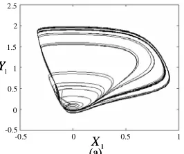
Chaotic system is a nonlinear deterministic system that displays complex, noisy-like and unpredictable dynamic behavior; it has been found in many engineering systems such as in biological system, chemical reactions, laser physics, secure communication and biomedical [13]. The issue of chaotic control system design has become a significant research topic in the physics, mathematics and engineering communities. This paper considers a model of two neurons coupled chaotic systems with a gap junction shown as Fig. 1 [16].
Adaptive TSK-Type Fuzzy Network Control for
Synchronization of a Coupled Nonlinear Chaotic
System
Chun-Fei Hsu, Ming-Ching Yen and Cheng-Hung Chuang
) (V
f Lm Cm f(V) Lm Cm
o
I Io
g
) (V
f Lm Cm f(V) Lm Cm
o
I Io
[image:2.595.58.275.53.168.2]g
Fig. 1. The circuit diagram of two coupled neurons.
The interest in chaos synchronization is the problem of how to design a controller to drive a slaver system to track a master system closely. Consider two neurons coupled chaotic systems as
Master system:
1 1
2 1 1 1 1
1
1 ( 1)(1 ) ( )
bX Y
I X X g Y rX X
X X
=
+ − − − − − =
& &
(1) Slave system:
2 2
1 2 2 2 2
2
2 ( 1)(1 ) ( )
bX Y
I u X X g Y rX X
X X
=
+ + − − − − − =
& &
(2) where Xi and Yi (i=1,2) are rescaled membrane voltage
and recovery variable of two neurons, respectively; g is the coupling strength of gap junction; I A ωt
ωcos
= is the external electrical stimulation with A and ω=2πf are the amplitude and frequency, respectively; and
u
is the control effort. The parameters of the coupled nonlinear cable model chaotic system are selected as A=0.1, b=1, r=10 and1271 . 0
=
f . As shown in Figs. 2 and 3, respectively, if the coupling strength of the gap junction g≤0.5 (g=0.01 in Fig. 2), the synchronization cannot occur; the synchronization occurs when g>0.5 (g =1.0 in Fig. 3).
To synchronize the two neurons coupled chaotic systems with a gap junction, define e1=X1−X2 and e2=Y1−Y2, then the error dynamical system can be expressed as
1 2
2 1 2 2
2 1 1
1
1 ( 1)(1 ) ( 1)(1 ) 2
be e
u e ge rX X
X rX X
X e
=
− − − − − −
− − =
& &
(3) Then the system dynamic can be rewritten as
] ) ( [z −u
+ =Ae b x e
& (4)
where T
X
X , ]
[ 1 2 =
x is the state vector; T e e, ] [ 2 1 =
e is the state error vector; ⎥
⎦ ⎤ ⎢
⎣ ⎡
− − =
g b
2 1 0
A ; T
] 1 , 0 [ =
b ; and
) 1 )( 1 ( ) 1 )( 1 ( )
( X1 X1 rX1 X2 X2 rX2
z x = − − − − − is the
system dynamic function. Assume all the parameters in (4) are well known, there exists an ideal controller as [17]
ke
x +
= ( ) *
z
u (5)
where k=[k1,k2] is the feedback gain vector. Substituting (5) into (4), the error dynamic becomes to
Λe e bk A
e=( − ) =
& (6)
where Λ=A−bk. Suppose the feedback gain vector k is chosen to correspond with the coefficients of a Hurwitz
polynomial, it implies that lim =0
∞ → e
t for any starting initial
conditions. Since the system dynamic function z(x) may be unknown or perturbed in the practical applications, the ideal controller (5) cannot be precisely obtained.
(a) 1
Y
1 X
-0.5 0 0.5 1
2.5
-0.5 0 0.5 1 1.5 2
(a) 1
Y
1 X
-0.5 0 0.5 1
2.5
-0.5 0 0.5 1 1.5 2
(b)
-0.5 0 0.5 1
2.5
-0.5 0 0.5 1 1.5 2
2 Y
2 X (b)
-0.5 0 0.5 1
2.5
-0.5 0 0.5 1 1.5 2
2 Y
2 X
(c)
-0.5 0 0.5 1
-0.5 0 0.5 1
1 X 2
X
(c)
-0.5 0 0.5 1
-0.5 0 0.5 1
1 X 2
X
(d)
0 0.5 1
1 Y -0.5
2.5
-0.5 0 0.5 1 1.5 2
2 Y
1.5 2
(d)
0 0.5 1
1 Y -0.5
2.5
-0.5 0 0.5 1 1.5 2
2 Y
[image:2.595.359.495.121.598.2]1.5 2
Fig. 2. The portraits on different planes without control for 01
. 0
=
g .
(a)
-0.5 0 0.5 1
2.5
-0.5 0 0.5 1 1.5 2
1 Y
1 X (a)
-0.5 0 0.5 1
2.5
-0.5 0 0.5 1 1.5 2
1 Y
[image:2.595.362.495.645.756.2](b)
-0.5 0 0.5 1
2.5
-0.5 0 0.5 1 1.5 2
2 Y
2 X (b)
-0.5 0 0.5 1
2.5
-0.5 0 0.5 1 1.5 2
2 Y
2 X
(c)
-0.5 0 0.5 1
-0.5 0 0.5 1
1 X 2
X
(c)
-0.5 0 0.5 1
-0.5 0 0.5 1
1 X 2
X
(d)
0 0.5 1
1 Y -0.5
2.5
-0.5 0 0.5 1 1.5 2
2 Y
1.5 2
(d)
0 0.5 1
1 Y -0.5
2.5
-0.5 0 0.5 1 1.5 2
2 Y
[image:3.595.105.238.50.410.2]1.5 2
Fig. 3. The portraits on different planes without control for 0
. 1 =
g .
master system
neural controller
fuzzy compensator
adaptive tuning law slave
system
⎥ ⎦ ⎤ ⎢ ⎣ ⎡
2 1
e e
1 1,Y
X
fc u
nc u
+ +
adaptive TSK-type fuzzy network control σ
c α&ˆ,&ˆ,&ˆ
+−
parameter tuning law
r&ˆ
afn
u
2
2
,
Y
X
master system
neural controller
fuzzy compensator
adaptive tuning law slave
system
⎥ ⎦ ⎤ ⎢ ⎣ ⎡
2 1
e e
1 1,Y
X
fc u
nc u
+ +
adaptive TSK-type fuzzy network control σ
c α&ˆ,&ˆ,&ˆ
+−
parameter tuning law
r&ˆ
afn
u
2
2
,
Y
X
2
2
,
Y
X
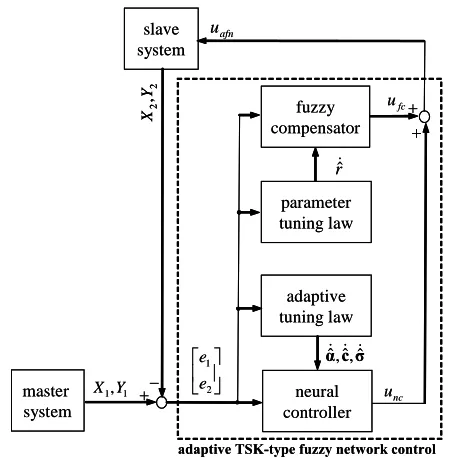
Fig. 4. Block diagram of the ATFNC for a coupled nonlinear chaotic system.
III. ATFNC SYSTEM DESIGN
This paper proposes an ATFNC system as shown in Fig. 4 which is composed of a neural controller and a fuzzy compensator, i.e.
fc nc
afn u u
u = + . (7)
The neural controller unc utilizes a TFNN to mimic the ideal
controller in (5) and the fuzzy compensator ufc is used to
compensate for the difference introduced by the neural controller.
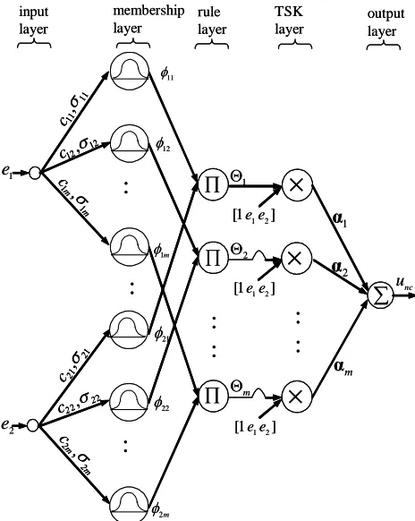
A. TFNN
Figure 5 shows the configuration of TFNN. The signal propagation and the basic function in each layer are as follows:
Layer 1 - Input layer: No function is performed in this layer. The node only transmits input values to layer 2.
Layer 2 - Membership layer: In this layer, each node performs a membership function and acts as a unit of memory. The Gaussian function is adopted as the membership function. For the jth node
(
)
( )
] exp[ 22
ij ij i ij
c x
σ
φ = − − , j=1,2,...,m (8)
where cij and σij are the mean and variance of the Gaussian
function in the jth term of the ith input linguistic variable xi,
respectively, and m is the total number of the linguistic variables with respect to the input nodes.
Layer 3 - Rule layer: According to the fuzzy AND operation by the algebraic product, the firing strength of the kth rule is calculated by
∏
==
Φ 2
1 ) , (
i ik k
k
k c σ φ , k=1,2,...,m. (9)
where T
k k k =[c1 c2 ]
c and T
k k k =[σ1 σ2 ]
σ .
Layer 4 - TSK layer: The TSK layer represents the linear combination function in the consequent part of the fuzzy system. Each node in this layer is denoted by
ξ αT
k k k k
k e e
u =α 0+α1 1+α 2 2= (10)
where T
k k k
k =[α 0,α1,α 2]
α is the parameter vector designed by the designer and T
e e, ] , 1 [ 1 2 =
ξ .
Layer 5 - Output layer: The output node together with links connected it act as a defuzzifier. The single node computes the overall output as the summation of all incoming signals. The output of TFNN can be represented as
∑
=Φ = m
k
k k k k
nc u
u 1
) ,
(c σ . (11)
Then, the output of TFNN can be represents in a vector form as
) , (cσ
Φ αT nc
u = (12)
where T T
m T
] ,..., [α1 α
α= ; T T
m T
] ,..., [ 1ξ ξ
Φ= Φ Φ ;
T T m T
] ,..., [c1 c
c= and T T
m T
] ,..., [σ1 σ
σ= .
In this paper, the TFNN is used to online mimic an ideal controller. By the approximation property, an ideal TFNN can be obtained as
∆ + = ∆ +
= * * * * *
*
) ,
(c σ α Φ
Φ
αT T
u (13)
where ∆ is the approximation error; α*
and Φ*
are the optimal parameter vectors of α and Φ, respectively; and c* and σ*
[image:3.595.53.278.448.677.2]Φ α σ c Φ
αˆ (ˆ,ˆ) ˆ ˆ
ˆ T T
nc
u = = (14)
where αˆ and Φˆ are the estimated parameter vectors of α and Φ , respectively; and cˆ and σˆ are the estimated parameter vectors of c and σ , respectively. Then, the estimation error is obtained as
nc u u u ˆ ~= *− Φ α Φ
α*T *+∆−ˆTˆ =
∆ + + +
=α~TΦˆ αˆTΦ~ α~TΦ~
(15) where α~=α*−αˆ
and Φ~ =Φ*−Φˆ
. The Taylor expansion linearization technique is employed to transform the nonlinear function into a partially linear form [7], i.e.
h
σ Φ
c
Φ
Φ= c + σ +
~ ~
~ T T
(16) where ~c=c*−cˆ
; σ~=σ*−σˆ
;
h
is a vector of high orderterms; c cc
c c Φ ˆ 1 | = ⎥⎦ ⎤ ⎢⎣ ⎡ ∂ Φ ∂ ∂ Φ ∂ = m
L ; and
σ σ σ σ σ Φ ˆ 1 | = ⎥⎦ ⎤ ⎢⎣ ⎡ ∂ Φ ∂ ∂ Φ ∂ = m
L . Substitute (16) into (15), yields
∆ + + + + +
=α~ Φˆ αˆ (Φc~c Φσσ~ h) ~α Φ~
~ T T T T T
u
ε
+ +
+
=α~ Φˆ ~c Φcαˆ σ~ Φσαˆ
T T
T
(17) where αˆ Φc~c ~c Φcαˆ
T T
T =
and αˆ Φσσ~ σ~ Φσαˆ
T T
T =
are used since they are scalars; and ε =αˆTh+α~TΦ~+∆
denotes the lump of approximation error and is assumed to be bounded by
E ≤ ε . 1 e nc u
∑
∏ output layer rule layer membership layer input layer 1 Θ:
:
2 e 1 α 2 α m α 11 φ 2 Θ m Θ 12 φ m 1 φ:
×
:
:
TSK layer:
21 φ 22 φ m 2 φ:
×
×
∏ ∏ 11 11, σ c 12 12,σc
m m c
1 1 ,σ
1 1, 2 2 c σ 2
2, 2
2 c σ 2m 2m c σ , ] 1 [ e1e2
] 1 [ e1e2
] 1 [ e1e2
1 e nc u
∑
∏ output layer rule layer membership layer input layer 1 Θ:
:
2 e 1 α 2 α m α 11 φ 2 Θ m Θ 12 φ m 1 φ:
×
:
:
TSK layer:
21 φ 22 φ m 2 φ:
×
×
∏ ∏ 11 11, σ c 11 11, σ c 12 12,σc12,σ12
c
m m c
1 1 ,σ
m m c
1 1 ,σ
1 1, 2 2 c σ 1 1, 2 2 c σ 2
2, 2
2
c22,σ22
c σ 2m 2m c σ , 2m 2m c σ , ] 1 [ e1e2
] 1 [ e1e2
[image:4.595.52.284.404.695.2]] 1 [ e1e2
Fig. 5. Network structure of TFNN.
B. Fuzzy Compensator Design
Assume the fuzzy compensator has 3 fuzzy rules in the rule base as given in the following form [18]
Rule 1: If eTPb
is PE, then ufc is r1 (18) Rule 2: If eTPb
is ZO, then ufc is r2 (19)
Rule 3: If eTPb
is NE, then ufc is r3 (20) where the triangular-typed functions and singletons are used to define the membership functions of IF-part and THEN-part, respectively. P is a symmetric positive definite matrix that satisfies the equation
Q
PΛ
P
ΛT + =−
(21) in which Q is a positive definite matrix. The defuzzification
of the output is accomplished by the method of center-of-gravity 3 3 2 2 1 1 3 1 3 1 w r w r w r w w r u i i i i i
fc = = + +
∑
∑
= =
(22)
where0≤w1≤1 , 0≤w2≤1 and0≤w3≤1 are the firing strengths of rules 1, 2, and 3, respectively; and the relation
1 3 2 1+w +w =
w is valid according to the special case of triangular membership function-based fuzzy system. In order to reduce the computation loading, let r1=rˆ, r2=0 and
r
r3=−ˆ. Hence, for any value of input, only one of four conditions will occur as
Condition1: Only rule 1 is triggered ( a T
s
>
Pb
e , w1=1 ,
0 3 2=w =
w )
r r
ufc = 1= ˆ. (23)
Condition2: Rules 1 and 2 are triggered simultaneously.
( a
T s
≤ <e Pb
0 , 0<w1,w2≤1 , w3=0) 1
1 1w rˆw
r
ufc = = . (24)
Condition3: Rules 2 and 3 are triggered simultaneously. ( <eTPb≤0
b
s , w1=0, 0<w2,w3≤1 ) 3
3 3w rˆw
r
ufc = =− . (25)
Condition 4: Only rule 3 is triggered. ( b T s ≤ Pb e , 0 2 1=w =
w , w3=1 )
r r
ufc = 3=−ˆ. (26)
Then, the (23)-(26) can be rewritten as )
( ˆ w1 w3 r
ufc = − . (27)
Moreover, it can see that
0 ) ( )
(w1−w3 = w1−w3 ≥
T
TPb ePb
e . (28)
C. Design of ATFNC System
Substituting (7) into (4), the error dynamic equation can be obtained as
] )
(
[z −unc−ufc
+ =Ae b x
e& . (29)
Using (5) and substituting (22) into (21) and using approximation error equation (20), (21) can be rewritten as
) ( ) ( * fc nc u u
u − −
+ −
= A bk e b e& ) ˆ ~ ˆ ~ ˆ ~
( T T T fc
u − + + + +
=Λe b α Φ c Φcα σ Φσα ε . (30) To guarantee the stability of the proposed ATFNC system, a
Lyapunov function is defined as
σ
α η η
η 2 ~ ~ 2 ~ ~ 2 ~ ~ 2 1 1 σ σ c c α α Pe e T c T T T
V = + + + (31)
where the positive constants ηα, ηc and ησ are the learning
using (30), yields
σ
α η η
η
σ σ
c c
α α
e P e Pe
e& & & & & & ~ ~ ~ ~ ~ ~
2 1 2
1 1
T
c T T T T
V = + + + +
) ~ ˆ (
~ ) ~ ˆ ( ~ 2
1
c T
T T
T T
η ηα
c
α
PbΦ
e c
α Φ
Pb e
α
Qe
e c
& &
+ +
+ +
− =
) ~ ˆ (
~
σ
η
σ α
PbΦ
e
σ σ
&
+ + T T
) ( fc
T
u
−
+e Pb ε (32)
If the adaptation laws of the neural controller are chosen as
Φ
Pb e
α
αˆ ~ T ˆ
α
η
= − = &
& (33)
α
PbΦ
e c
c cˆ
~
ˆ T
c
η
= − = &
& (34)
α
PbΦ
e
σ
σˆ ~ σˆ
T σ
η
= − = &
& (35)
then (32) can be rewritten as ) ( 2
1
1 fc
T T
u V& = − eQe+e Pb ε−
Pb e Pb
e Qe
eT T T
w w rˆ( ) 2
1
3 1−
− +
−
= ε
Pb e Qe
eT ( rˆw w ) T
2 1
3 1−
− + −
≤ ε (36)
If the following inequality
3 1 ˆ
w w r
−
> ε (37)
holds, then the sliding condition V&1≤0 can be satisfied. Owing to the unknown lumped uncertainties, the value rˆ cannot be exactly obtained in advance for practical applications. According to (37), there exists an ideal value *
r as following to achieve minimum value
κ ε
+ − =
3 1 *
w w
r (38)
where κ is a positive constant. Thus, a simple adaptive algorithm is utilized in this study to estimate the ideal value of *
r , and its estimated error is defined as r
r
r ˆ
~= *−
(39) where rˆ is the estimated value of the optimal value of *
r . Then, define a new Lyapunov function candidate in the following form
2 1
2
~ 2
1 r V V
r
η
+
= (40)
where ηr is the learning rate with a positive constant.
Differentiating (40) with respect to time and using (30), (33)-(35), it is obtained
r r V
r T
c T T T
T & & & & &
&
& ~ ~ ~ ~ ~ ~ 1 ~~ 2
1 2
1
2 η η η η
σ α
+ + + + +
= ePe e Pe α α c c σ σ
Pb e Pb
e Qe
e T
r T
T r w w r ε
η +
+ −
+ −
= ~[( ) 1 ~] 2
1
3
1 &
Pb
eT
w w r ( 1 3)
* −
− (41)
Choose the fuzzy tuning law as
Pb
eT
r w w
r
r ˆ ( )
~
3 1−
− = − = & η
& (42)
and using (37), (41) becomes
Pb e Pb
e Qe
eT T T
w w r
V ( )
2 1
3 1 *
2 + − −
−
= ε
&
0 2
1
3
1− ≤
− −
≤ eTQe eTPb w w
κ . (43)
As a result, the stability of the proposed ATFNC system can be guaranteed.
IV. SIMULATION RESULTS
It should be emphasized the development of the ATFNC system doesn’t need to know the system dynamic of the controlled system. The parameters of the ATFNC system can be online tuned by the proposed adaptive laws. The parameters for the ATFNC system are selected as k1=k2=4,
10
=
α
η , ηc =ησ =1 and ηr=0.1. All the parameters are
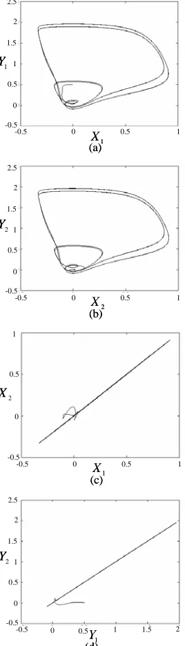
chosen through some trials considering the requirement of stability. The simulation results of the ATFNC system are shown in Figs. 6 and 7 for g=0.01 and g=1.0 , respectively. The phase portraits on plan of X1−Y1 are shown in Figs. 6(a) and 7(a); the phase portraits on plan of
2 2 Y
X − are shown in Figs. 6(b) and 7(b); the phase portraits on plan of X1−X2 are shown in Figs. 6(c) and 7(c); and the phase portraits on plan of Y1−Y2 are shown in Figs. 6(d) and 7(d), respectively. It can be seen that there is no chattering phenomena in the control effort and perfect tracking response can be obtained after initial transient response.
(a)
-0.5 0 0.5 1
2.5
-0.5 0 0.5 1 1.5 2
1 Y
1 X (a)
-0.5 0 0.5 1
2.5
-0.5 0 0.5 1 1.5 2
1 Y
1 X
(b)
-0.5 0 0.5 1
2.5
-0.5 0 0.5 1 1.5 2
2 Y
2 X (b)
-0.5 0 0.5 1
2.5
-0.5 0 0.5 1 1.5 2
2 Y
2 X
(c)
-0.5 0 0.5 1
-0.5 0 0.5 1
1 X 2
X
(c)
-0.5 0 0.5 1
-0.5 0 0.5 1
1 X 2
(d)
0 0.5 1
1 Y -0.5
2.5
-0.5 0 0.5 1 1.5 2
2 Y
1.5 2
(d)
0 0.5 1
1 Y -0.5
2.5
-0.5 0 0.5 1 1.5 2
2 Y
[image:6.595.105.238.52.166.2]1.5 2
Fig. 6. The simulation results of the ATFNC system for 01
. 0
=
g .
(a)
-0.5 0 0.5 1
2.5
-0.5 0 0.5 1 1.5 2
1 Y
1 X (a)
-0.5 0 0.5 1
2.5
-0.5 0 0.5 1 1.5 2
1 Y
1 X
(b)
-0.5 0 0.5 1
2.5
-0.5 0 0.5 1 1.5 2
2 Y
2 X (b)
-0.5 0 0.5 1
2.5
-0.5 0 0.5 1 1.5 2
2 Y
2 X
(c)
-0.5 0 0.5 1
-0.5 0 0.5 1
1 X 2
X
(c)
-0.5 0 0.5 1
-0.5 0 0.5 1
1 X 2
X
(d)
0 0.5 1
1 Y -0.5
2.5
-0.5 0 0.5 1 1.5 2
2 Y
1.5 2
(d)
0 0.5 1
1 Y -0.5
2.5
-0.5 0 0.5 1 1.5 2
2 Y
1.5 2
Fig. 7. The simulation results of the ATFNC system for 0
. 1
=
g .
V. CONCLUSION
This paper has successfully developed an adaptive TSK-type fuzzy network control (ATFNC) system. All the parameters of the proposed ATFNC system are online tuned
based on the Lyapunov stability theorem; thus the stability of the closed-loop control system can be guaranteed. Finally, the proposed ATFNC system is applied to a coupled nonlinear chaotic system. The effectiveness of the ATFNC system using a fuzzy compensator is verified by some simulations. The fuzzy compensation controller design uses a simple fuzzy system can remove completely the chattering phenomena.
ACKNOWLEDGMENT
The authors appreciate the partial financial support from the National Science Council of Republic of China under grant NSC 99-2628-E-216-002.
REFERENCES
[1] C. T. Lin, C. S. G. Lee, Neural Fuzzy Systems: A Neuro-Fuzzy Synergism to Intelligent Systems, Englewood Cliffs, NJ: Prentice -Hall, 1996.
[2] D. Nauck, F. Klawonn, R. Kruse, Foundations of Neuro-Fuzzy Systems, New York: Wiley, 1997.
[3] C. F. Juang, C. Lo, Zero-order TSK-type fuzzy system learning using a two-phase swarm intelligence, Fuzzy Sets and Systems, vol. 159, pp. 2910-2926, 2008.
[4] C. H. Chen, C. J. Lin, C. T. Lin, A functional-link-based neuro-fuzzy network for nonlinear system control, IEEE Trans. Fuzzy Systems, vol. 16, pp. 1362-1378, 2008.
[5] R. J. Wai, P. C. Chen, Intelligent tracking control for robot manipulator including actuator dynamics via TSK-type fuzzy neural network, IEEE Trans. Fuzzy Systems, vol. 12, pp. 552-560, 2004.
[6] C. J. Lin, Y. J. Xu, A self-adaptive neural fuzzy network with group-based symbiotic evolution and its prediction applications,Fuzzy Sets and Systems, vol. 157, pp. 1036-1056, 2006.
[7] C. F. Hsu, Self-organizing adaptive fuzzy neural control for a class of nonlinear systems, IEEE Trans. Neural Networks, vol. 18, pp. 1232-1241, 2007.
[8] F. J. Lin, S. Y. Chen, L. T. Teng, H. Chu, A recurrent FL-based fuzzy neural network controller with improved particle swarm optimization for linear synchronous motor drive, IEEE Trans. Magnetics, vol. 45, pp. 3151-3165, 2009.
[9] K. H. Cheng, C. F. Hsu, C. M. Lin, T. T. Lee, C. Li, Fuzzy-neural sliding-mode control for DC-DC converters using asymmetric Gaussian membership functions, IEEE Trans. Industrial Electronics, vol. 54, pp. 1528-1536, 2007.
[10] T. F. Wu, P. S. Tsai, F. R. Chang, L. S. Wang, Adaptive fuzzy CMAC control for a class of nonlinear system with smooth compensation, IEE Proc. Control Theory and Applications, vol. 153, pp. 647-657, 2006. [11] Y. F. Peng, C. M. Lin, Intelligent motion control of linear ultrasonic
motor with ∞
H tracking performance, IET Control Theory Applications, vol. 1, pp. 9-17, 2007.
[12] C. K. Lin, Fuzzy-basis-function-network-based H∞ tracking control
for robotic manipulators using only position feedback, IEEE Trans. Fuzzy Systems, vol. 17, pp. 1208-1216, 2009.
[13] H. K. Chen, Chaos and chaos synchronization of a symmetric gyro with linear-plus-cubic damping, Journal of Sound Vibration, vol. 255, pp. 719-740, 2002.
[14] H. T. Yau, Nonlinear rule-based controller for chaos synchronization of two gyros with linear-plus-cubic damping, Chaos Solitons and Fractals, vol. 34, pp. 1357-1365, 2007.
[15] C. M. Lin, M. H. Lin, Y. F. Peng, Synchronization of chaotic gyro systems using recurrent wavelet CMAC, Cybernetics and Systems, vol. 41, pp. 391-405, 2010.
[16] Y. Q. Chen, J. Wang, W. L. Chan, K. M. Tsang, Chaos synchronization of coupled neurons under electrical stimulation via robust adaptive fuzzy control, Nonlinear Dynamics, vol. 61, pp. 847-857, 2010. [17] J. J. E. Slotine, W. P. Li, Applied Nonlinear Control, Englewood Cliffs,
NJ: Prentice Hall, 1991.
[image:6.595.104.238.216.684.2]