Intelligent WAN
Technology Design Guide
January 2015
Table of Contents
Preface ... 1 CVD Navigator ... 2 Use Cases ...2 Scope ...2 Proficiency ...2 Introduction ... 3Technology Use Cases ...3
Use Case: Secure Site-to-Site WAN Communications ...3
Cisco Intelligent WAN Overview ...4
Transport Independence ...4
Intelligent Path Control ...5
Application Optimization ...5
Secure Connectivity ...5
Design Overview ...5
Transport-Independent WAN Design ...5
IP Multicast ...15
Quality of Service ...15
Intelligent Path Control ...16
Deploying the Cisco Intelligent WAN ... 18
Overall IWAN Architecture Design Goals ...18
Overlay Transport (DMVPN) ...18
IP Routing (EIGRP) ...18
Quality of Service ...18
Path Optimization (Performance Routing) ...19
LAN Access ...19
Deploying the Transport Independent Design ... 20
Design Overview ...20
DMVPN Hub Routers ...20
Remote Sites—DMVPN Spoke Router Selection ...20
VRFs and Front Door VRF ...21
Design Details ...23
EIGRP ...24
Encryption ...24
DMVPN ...25
Deployment Details ...27
Configuring an IOS Certificate Authority ...27
Configuring DMVPN Hub Router ...34
Configuring the Firewall and DMZ Switch ...55
Configuring Remote-Site DMVPN Router ...65
Adding Second DMVPN for a Single-Router Remote Site ...88
Adding LTE fallback DMVPN for a single-router remote site ...99
Modifying the First Router for Dual Router Design ... 114
Configuring Remote-Site DMVPN Router (Router 2) ... 119
Deploying an IWAN Remote-Site Distribution Layer ... 146
Connecting Remote-site Router to Distribution Layer ...146
Connecting Remote-Site Router to Distribution Layer (Router 2) ...153
Deploying IWAN Quality of Service ... 158
Configuring QoS for DMVPN Routers ...158
Applying DMVPN QoS Policy to DMVPN Hub Routers ...164
Applying QoS Configurations to Remote Site Routers ...168
Deploying IWAN Performance Routing...173
Configuring PfR Hub Master Controller ...175
Configuring Performance Routing for Hub Location ...181
Configuring PfR for Remote Site Locations ...189
Deploying IWAN Monitoring ... 202
Configuring Flexible NetFlow for IWAN Monitoring ...202
Appendix A: Product List ...210
Appendix B: Technical Feature Supplement ...213
Front Door VRF for DMVPN ... 213
Preface
Cisco Validated Designs (CVDs) present systems that are based on common use cases or engineering priorities. CVDs incorporate a broad set of technologies, features, and applications that address customer needs. Cisco engineers have comprehensively tested and documented each design in order to ensure faster, more reliable, and fully predictable deployment.
CVDs include two guide types that provide tested design details:
• Technology design guides provide deployment details, information about validated products and software, and best practices for specific types of technology.
• Solution design guides integrate existing CVDs but also include product features and functionality across Cisco products and sometimes include information about third-party integration.
Both CVD types provide a tested starting point for Cisco partners or customers to begin designing and deploying systems.
CVD Foundation Series
This CVD Foundation guide is a part of the January 2015 Series. As Cisco develops a CVD Foundation series, the guides themselves are tested together, in the same network lab. This approach assures that the guides in a series are fully compatible with one another. Each series describes a lab-validated, complete system.
The CVD Foundation series incorporates wired and wireless LAN, WAN, data center, security, and network management technologies. Using the CVD Foundation simplifies system integration, allowing you to select solutions that solve an organization’s problems—without worrying about the technical complexity.
To ensure the compatibility of designs in the CVD Foundation, you should use guides that belong to the same release. For the most recent CVD Foundation guides, please visit the CVD Foundation web site.
Comments and Questions
CVD Navigator
The CVD Navigator helps you determine the applicability of this guide by summarizing its key elements: the use cases, the scope or breadth of the technology covered, the proficiency or experience recommended, and CVDs related to this guide. This section is a quick reference only. For more details, see the Introduction.
Use Cases
This guide addresses the following technology use cases:
• Use Case: Secure Site-to-Site WAN Communications — This guide helps organizations connect remote sites over private (MPLS VPN) and public (Internet) IP networks, efficiently and securely.
For more information, see the “Use Cases” section in this guide.
Scope
This guide covers the following areas of technology and products: • Dynamic Multipoint Virtual Private Network (DMVPN) design
and deployment over public and private WAN transport • Transport Independent Design (TID) provides capabilities for
easy multi-homing over any carrier service offering, including MPLS, broadband, and cellular 3G/4G/LTE
• Intelligent Path Control with Cisco Performance Routing (PfR) improves application delivery and WAN efficiency
• Secure connectivity protects the corporate communications and offloads user traffic directly to the Internet
• WAN quality of server (QoS) design and configuration For more information, see the “Design Overview” section in this guide.
Proficiency
This guide is for people with the following technical proficiencies or equivalent experience:
• CCNP Routing and Switching • CCNP Security
To view the related CVD guides, click the titles or visit the CVD Foundation web site.
Related CVD Guides
VALIDATED DESIGN
Firewall and IPS Technology
Design Guide
VALIDATED DESIGNMPLS WAN Technology
Design Guide
VALIDATED DESIGNVPN WAN Technology
Design Guide
Introduction
The Cisco Intelligent WAN (IWAN) solution provides design and implementation guidance for organizations looking to deploy wide area network (WAN) transport with a transport-independent design (TID), intelligent path control, application optimization, and secure encrypted communications between branch locations while reducing the operating cost of the WAN. IWAN takes full advantage of cost-effective transport services in order to increase bandwidth capacity without compromising performance, reliability, or security of collaboration or cloud-based applications.
Technology Use Cases
Organizations require the WAN to provide sufficient performance and reliability for the remote-site users to be effective in supporting the business. Although most of the applications and services that the remote-site worker uses are centrally located, the WAN design must provide the workforce with a common resource-access experience, regardless of location.
Carrier-based MPLS service is not always available or cost-effective for an organization to use exclusively for remote-site WAN connectivity. There are multiple WAN transport offerings that can be used simultaneously to create a robust, secure, and cost-effective WAN, including MPLS VPNs, Internet, Cellular (3G/LTE), and Carrier Ethernet. Internet-based IP VPNs offer attractive bandwidth pricing and can augment premium MPLS offerings or replace MPLS in some scenarios. A flexible network architecture should include all common WAN transport offerings as options without significantly increasing the complexity of the overall design.
While Internet IP VPN networks present an attractive option for effective WAN connectivity, anytime an organization sends data across a public network there is risk that the data will be compromised. Loss or corruption of data can result in a regulatory violation and can present a negative public image, either of which can have significant financial impact on an organization. Secure data transport over public networks like the Internet requires adequate encryption to protect business information.
Use Case: Secure Site-to-Site WAN Communications
This guide helps organizations connect remote sites over private (MPLS VPN) and public (Internet) IP networks, efficiently and securely.
This design guide enables the following network capabilities:
• Secure, encrypted communications solutions for up to 2000 locations by using a dynamic multipoint VPN (DMVPN) IPsec tunnel overlay configuration
• A multi-homed active-active connectivity solution for resiliency and efficient use of all WAN bandwidth, using single or dual routers in remote locations
• Support for IP Multicast and replication performed on core, hub-site routers
Cisco Intelligent WAN Overview
With the advent of globalization, WANs have become a major artery for communication between remote offices and customers in any corner of the world. Additionally, with data center consolidation, applications are moving to centralized data centers and clouds. WANs now play an even more critical role, because business survival is dependent on the availability and performance of the network.
Until now, the only way to get reliable connectivity with predictable performance was to take advantage of a private WAN using MPLS or leased line service. However, carrier-based MPLS and leased line services can be expensive and are not always cost-effective for an organization to use for WAN transport in order to support growing bandwidth requirements for remote-site connectivity. Organizations are looking for ways to lower operating budget while adequately providing the network transport for a remote site.
As bandwidth demands have increased, the Internet has become a much more stable platform, and the price-to-performance gains are very attractive. However, businesses are primarily deploying “Internet as WAN” in their smaller sites or as a backup path because of the risks. Now this cost-effective, performance-enhancing opportunity can be realized at all your branch offices with Cisco IWAN.
Cisco IWAN enables organizations to deliver an uncompromised experience over any connection. With Cisco IWAN IT organizations can provide more bandwidth to their branch office connections by using less expensive WAN transport options without affecting performance, security, or reliability. With the IWAN solution, traffic is dynamically routed based on application service-level agreement (SLA), endpoint type, and network conditions in order to deliver the best quality experience. The realized savings from IWAN not only pays for the infrastructure upgrades, but also frees resources for business innovation.
Figure 1 - Cisco IWAN solution components
Transport Independence
Using DMVPN, IWAN provides capabilities for easy multi-homing over any carrier service offering, including MPLS, broadband, and cellular 3G/4G/LTE. More importantly, the design simplifies the routing design with a single routing control plane and minimal peering to providers, making it easy for organizations to mix and match and change providers and transport options. Two or more WAN transport providers are recommended in order to increase network availability up to 99.999%. Additionally, the Cisco DMVPN solution provides an industry-proven and U.S. government FIPS 140-2 certified IPsec solution for data privacy and integrity protection, as
well as automatic site-to-site IP security (IPsec) tunnels. These tunnels can be set up using pre-shared keys or using a public key infrastructure with a certificate authority in the demilitarized zone (DMZ) in order to enroll and authorize the use of keys between routers.
Intelligent Path Control
Cisco Performance Routing (PfR) improves application delivery and WAN efficiency. PfR dynamically controls data packet forwarding decisions by looking at application type, performance, policies, and path status. PfR monitors the network performance—jitter, packet loss, and delay—and makes decisions to forward critical applications over the best-performing path based on the application policy. Cisco PfR can intelligently load-balance traffic to efficiently use all available WAN bandwidth. IWAN intelligent path control is the key to providing a business-class WAN over Internet transport.
Application Optimization
Cisco Application Visibility and Control (AVC) and Cisco Wide Area Application Services (WAAS) provide application performance visibility and optimization over the WAN. With applications becoming increasingly opaque due to the increased reuse of well-known ports such as HTTP (port 80), static port classification of applications is no longer sufficient. Cisco AVC provides application awareness with deep packet inspection of traffic in order to identify and monitor applications’ performance. Cisco AVC allows IT to determine what traffic is running across the network, tune the network for business-critical services, and resolve network problems. With increased visibility into the applications on the network, better QoS and PfR policies can be enabled to help ensure that critical applications are properly prioritized across the network. Cisco WAAS provides application-specific acceleration capabilities that improve response times while reducing WAN bandwidth requirements.
Secure Connectivity
Secure connectivity protects the corporate communications and offloads user traffic directly to the Internet. Strong IPsec encryption, zone-based firewalls, and strict access controls are used to protect the WAN over the public Internet. Routing remote-site users directly to the Internet improves public cloud application performance while reducing traffic over the WAN. Cisco Cloud Web Security (CWS) service provides a cloud-based web proxy to centrally manage and secure user traffic accessing the Internet.
Design Overview
The Cisco Intelligent WAN Design Guide provides a design that enables highly available, secure, and optimized connectivity for multiple remote-site local area networks (LANs).
Transport-Independent WAN Design
A transport-independent design simplifies the WAN deployment by using an IPsec VPN overlay over all WAN transport options including MPLS, Internet, and Cellular (3G/4G). A single VPN overlay reduces routing and security complexity, and provides flexibility in choosing providers and transport options. Cisco DMVPN provides the IWAN IPsec overlay.
DMVPN makes use of multipoint generic routing encapsulation (mGRE) tunnels to interconnect the hub to all of the spoke routers. These mGRE tunnels are also sometimes referred to as DMVPN clouds in this context. This technology combination supports unicast, multicast, and broadcast IP, including the ability to run routing protocols within the tunnels.
Internet as WAN Transport
The Internet is essentially a large-scale public IP WAN composed of multiple interconnected service providers. The Internet can provide reliable high-performance connectivity between various locations, although it lacks any explicit guarantees for these connections. Despite its “best effort” nature, the Internet is a sensible choice for augmenting premium MPLS VPN transports or as a primary WAN transport in some cases. The IWAN architecture leverages two or more providers for resiliency and application availability. Provider path diversity provides the foundation for PfR to route around fluctuations in the providers’ performance.
Internet connections are typically included in discussions relevant to the Internet edge, specifically for the primary site. Remote-site routers also commonly have Internet connections but do not provide the same breadth of services using the Internet. For security and other reasons, Internet access at remote sites is often routed through the primary site.
This design guide uses both MPLS and the Internet for VPN site-to-site connections.
Dynamic Multipoint VPN
DMVPN is a solution for building scalable site-to-site VPNs that support a variety of applications. DMVPN is widely used for encrypted site-to-site connectivity over public or private IP networks and can be implemented on all WAN routers used in this design guide.
DMVPN was selected for the secure overlay WAN solution because DMVPN supports on-demand full mesh connectivity over any carries transport with a simple hub-and-spoke configuration. DMVPN also supports spoke routers that have dynamically assigned IP addresses.
DMVPN makes use of multipoint generic routing encapsulation (mGRE) tunnels to interconnect the hub to all of the spoke routers. These mGRE tunnels are also sometimes referred to as DMVPN clouds in this context. This technology combination supports unicast, multicast, and broadcast IP, including the ability to run routing protocols within the tunnels.
Ethernet
The WAN transports mentioned previously use Ethernet as a standard media type. Ethernet is becoming a dominant carrier handoff in many markets and it is relevant to include Ethernet as the primary media in the tested architectures. Much of the discussion in this guide can also be applied to non-Ethernet media (such as T1/E1, DS-3, OC-3, and so on), but they are not explicitly discussed.
WAN-Aggregation Designs
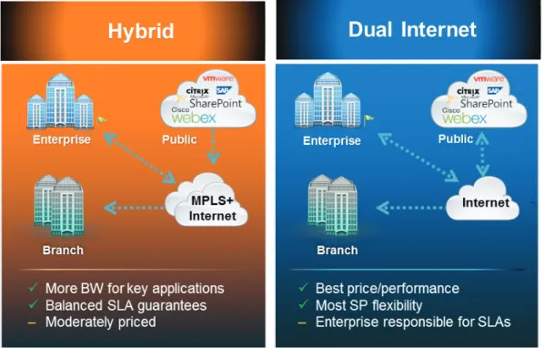
This guide describes two IWAN design models.
The first design model is the IWAN Hybrid, which uses MPLS paired with Internet VPN as WAN transports. In this design model, the MPLS WAN can provide more bandwidth for the critical classes of services needed for key applications and can provide SLA guarantees for these applications. The second design model is the IWAN Dual Internet, which uses a pair of Internet service providers to further reduce cost while maintaining a high level of resiliency for the WAN. A third design model, the IWAN Dual MPLS, is not covered in this guide.
Figure 2 - Cisco IWAN design models
The IWAN WAN-aggregation (hub) designs for both design models include two WAN edge routers.
When WAN aggregation routers are referred to in the context of the connection to a carrier or service provider, they are typically known as customer edge (CE) routers. WAN aggregation routers that terminate VPN traffic are referred to as VPN hub routers. In the context of IWAN, a MPLS A CE router is also used as a VPN hub router. Regardless of the design model, the WAN aggregation routers always connect into a pair of distribution layer switches.
Each of the design models is shown with LAN connections into either a collapsed core/distribution layer or a dedicated WAN distribution layer. From the WAN-aggregation perspective, there are no functional differences between these two methods.
In all of the WAN-aggregation designs, tasks such as IP route summarization are performed at the distribution layer. There are other various devices supporting WAN edge services, and these devices should also connect into the distribution layer.
IWAN Hybrid Design Model
The IWAN Hybrid design model: • Has a single MPLS VPN carrier. • Uses a single Internet carrier.
• Uses front-door virtual routing and forwarding (FVRF) on both MPLS and Internet links, with static default routing within the FVRF.
FVRF provides control plane separation from the providers and an additional security layer between inside and outside networks.
Figure 3 - WAN aggregation: IWAN hybrid design model
WAN Distribution Layer Core Layer DMVPN 2 1219 MPLS DMVPN 1 Internet Edge DMVPN Hub
Router (MPLS) DMVPN HubRouter (INET)
INET
In both the IWAN Hybrid and IWAN Dual Internet design models, the DMVPN hub routers connect to the Internet indirectly through a firewall DMZ interface contained within the Internet edge. For details about the connection to the Internet, see the Firewall and IPS Technology Design Guide. The VPN hub routers are connected into the firewall DMZ interface, rather than connected directly with Internet service-provider routers. A firewall connection is typically not used when the VPN hub router connects to a MPLS carrier.
IWAN Dual Internet Design Model
The IWAN Dual Internet design model: • Uses two Internet carriers.
• Uses Front Door VRF (FVRF) on both Internet links, with static default routing within the FVRF.
Figure 4 - WAN aggregation: IWAN dual Internet design model
WAN Distribution Layer Core Layer DMVPN 4 1220 DMVPN 3 Internet Edge DMVPN Hub
Router (INET 1) DMVPN HubRouter (INET 2)
INET ISP A / ISP B
WAN Remote-Site Designs
This guide documents multiple WAN remote-site designs, and they are based on various combinations of WAN transports mapped to the site specific requirements for service levels and redundancy.
Figure 5 - WAN remote-site design options
Link Resiliency with Dual Routers Link Resiliency
1221
IWAN Hybrid IWAN Dual Internet
MPLS Internet Internet Internet
The remote-site designs include single or dual WAN edge routers. The remote-site routers are DMVPN spokes to the primary site hubs.
Most remote sites are designed with a single router WAN edge; however, certain remote-site types require a dual router WAN design. Dual router candidate sites include regional office or remote campus locations with large user populations or sites with business critical needs that justify additional redundancy to remove single points of failure.
The overall WAN design methodology is based on a primary WAN-aggregation site design that can
accommodate all of the remote-site types that map to the various link combinations listed in the following table.
Table 1 - WAN remote-site transport options
WAN remote-site routers WAN transports Primary transport Secondary transport
Single Dual MPLS VPN Internet
Dual Dual MPLS VPN Internet
Single Dual Internet Internet
Dual Dual Internet Internet
This design guide also includes information for adding an LTE fallback DMVPN for a single-router remote site.
Table 2 - WAN remote-site transport options with LTE fallback
WAN remote-site routers WAN transports Primary transport Secondary transport Tertiary transport
Single Dual w/ fallback MPLS VPN Internet 4G LTE
Single Dual w/ fallback Internet Internet 4G LTE
The modular nature of the IWAN network design enables you to create design elements that can be replicated throughout the network.
The WAN-aggregation designs and all of the WAN remote-site designs are standard building blocks in the overall design. Replication of the individual building blocks provides an easy way to scale the network and allows for a consistent deployment method.
WAN/LAN Interconnection
The primary role of the WAN is to interconnect primary site and remote-site LANs. The LAN discussion within this guide is limited to how the WAN-aggregation site LAN connects to the WAN-aggregation devices and how the remote-site LANs connect to the remote-site WAN devices. Specific details regarding the LAN components of the design are covered in the Campus Wired LAN Technology Design Guide.
At remote sites, the LAN topology depends on the number of connected users and physical geography of the site. Large sites may require the use of a distribution layer to support multiple access layer switches. Other sites may only require an access layer switch directly connected to the WAN remote-site routers. The variants that are tested and documented in this guide are shown in the following table.
Table 3 - WAN remote-site LAN options
WAN remote-site routers WAN transports LAN topology
Single Dual Access only
Distribution/Access
Dual Dual Access only
Distribution/Access
WAN Remotes Sites—LAN Topology
For consistency and modularity, all WAN remote sites use the same VLAN assignment scheme, which is shown in the following table. This design guide uses a convention that is relevant to any location that has a single access switch and this model can also be easily scaled to additional access closets through the addition of a distribution layer.
Table 4 - WAN remote-sites: VLAN assignment
VLAN Usage Layer 2 access Layer 3 distribution/access
VLAN 64 Data 1 Yes —
VLAN 69 Voice 1 Yes —
VLAN 99 Transit Yes
(dual router only)
Yes
(dual router only)
VLAN 50 Router Link (1) — Yes
VLAN 54 Router Link (2) — Yes
(dual router only)
Layer 2 Access
WAN remote sites that do not require additional distribution layer routing devices are considered to be flat or from a LAN perspective they are considered un-routed Layer 2 sites. All Layer 3 services are provided by the attached WAN routers. The access switches, through the use of multiple VLANs, can support services such as data and voice. The design shown in the following figure illustrates the standardized VLAN assignment scheme. The benefits of this design are clear: all of the access switches can be configured identically, regardless of the number of sites in this configuration.
Access switches and their configuration are not included in this guide. The Campus Wired LAN Technology Design Guide provides configuration details on the various access switching platforms.
IP subnets are assigned on a per-VLAN basis. This design only allocates subnets with a 255.255.255.0 netmask for the access layer, even if less than 254 IP addresses are required. (This model can be adjusted as necessary to other IP address schemes.) The connection between the router and the access switch must be configured for 802.1Q VLAN trunking with sub-interfaces on the router that map to the respective VLANs on the switch. The various router sub-interfaces act as the IP default gateways for each of the IP subnet and VLAN combinations.
Figure 6 - WAN remote site with flat layer 2 LAN (single router) Internet No HSRP Required VLAN 64 - Data 802.1Q VLAN Trunk (64, 69) VLAN 69 - Voice 2140
A similar LAN design can be extended to a dual-router edge as shown in the following figure. This design change introduces some additional complexity. The first requirement is to run a routing protocol. You need to configure enhanced interior gateway routing protocol (EIGRP) between the routers.
Because there are now two routers per subnet, a first-hop redundancy protocol (FHRP) must be implemented. For this design, Cisco selected hot standby router protocol (HSRP) as the FHRP. HSRP is designed to allow for transparent failover of the first-hop IP router. HSRP provides high network availability by providing first-hop routing redundancy for IP hosts configured with a default gateway IP address. HSRP is used in a group of routers for selecting an active router and a standby router. When there are multiple routers on a LAN, the active router forwards the packets; the standby router is the router that takes over when the active router fails or when preset conditions are met.
Figure 7 - WAN remote site with flat layer 2 LAN (dual router)
WAN WAN
Active HSRP Router VLAN 64 - Data VLAN99 - Transit 802.1Q VLAN Trunk (64, 69, 99) VLAN 69 - Voice 2141 HSRP VLANs EIGRP
Enhanced object tracking (EOT) provides a consistent methodology for various router and switching features to conditionally modify their operation based on information objects available within other processes. The objects that can be tracked include interface line protocol, IP route reachability, and IP SLA reachability, as well as several others.
To improve convergence times after a primary WAN failure, HSRP has the capability to monitor the line-protocol status of the DMVPN tunnel interface. This capability allows for a router to give up its HSRP Active role if its DMVPN hub becomes unresponsive, and that provides additional network resiliency.
HSRP is configured to be active on the router with the highest priority WAN transport. EOT of the primary
DMVPN tunnel is implemented in conjunction with HSRP so that in the case of WAN transport failure, the standby HSRP router associated with the lower priority (alternate) WAN transport becomes the active HSRP router. The dual router designs also warrant an additional component that is required for proper routing in certain scenarios. In these cases, a traffic flow from a remote-site host might be sent to a destination reachable via the alternate WAN transport (for example, a dual DMVPN remote site communicating with a DMVPN2-only remote site). The primary WAN transport router then forwards the traffic out the same data interface to send it to the alternate WAN transport router, which then forwards the traffic to the proper destination. This is referred to as hairpinning.
The appropriate method to avoid sending the traffic out the same interface is to introduce an additional link between the routers and designate the link as a transit network (Vlan 99). There are no hosts connected to the transit network, and it is only used for router-router communication. The routing protocol runs between router sub-interfaces assigned to the transit network. No additional router interfaces are required with this design modification because the 802.1Q VLAN trunk configuration can easily accommodate an additional sub-interface.
Distribution and Access Layer
Large remote sites may require a LAN environment similar to that of a small campus LAN that includes a distribution layer and access layer. This topology works well with either a single or dual router WAN edge. To implement this design, the routers should connect via EtherChannel links to the distribution switch. These EtherChannel links are configured as 802.1Q VLAN trunks, to support both a routed point-to-point link to allow EIGRP routing with the distribution switch, and in the dual router design, to provide a transit network for direct communication between the WAN routers.
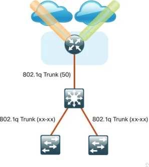
Figure 8 - IWAN single router remote-site: Connection to distribution layer
1222
VLAN 50 - Router 1 Link
802.1q Trunk (xx-xx) 802.1q Trunk (50)
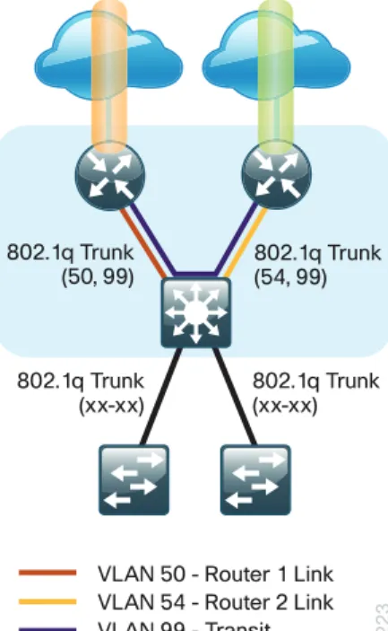
Figure 9 - IWAN dual router remote-site: Connection to distribution layer
VLAN 50 - Router 1 Link 802.1q Trunk
(xx-xx) 802.1q Trunk(xx-xx) 802.1q Trunk
(50, 99) 802.1q Trunk(54, 99)
VLAN 54 - Router 2 Link VLAN 99 - Transit 1223
The distribution switch handles all access layer routing, with VLANs trunked to access switches. No HSRP is required when the design includes a distribution layer. A full distribution and access layer design is shown in the following figure.
Figure 10 - IWAN dual router remote-site: Distribution and access layer
VLAN 50 - Router 1 Link 802.1q Trunk
(xx-xx) 802.1q Trunk(xx-xx) 802.1q Trunk
(50, 99) 802.1q Trunk(54, 99)
VLAN 54 - Router 2 Link VLAN 99 - Transit 1224 Data
Voice
Data
IP Multicast
IP Multicast allows a single IP data stream to be replicated by the infrastructure (routers and switches) and sent from a single source to multiple receivers. IP Multicast is much more efficient than multiple individual unicast streams or a broadcast stream that would propagate everywhere. IP telephony music on hold (MOH) and IP video broadcast streaming are two examples of IP Multicast applications.
To receive a particular IP Multicast data stream, end hosts must join a multicast group by sending an Internet group management protocol (IGMP) message to their local multicast router. In a traditional IP Multicast design, the local router consults another router in the network acting as a rendezvous point (RP). An RP maps the receivers to active sources so the end hosts can join their streams.
The RP is a control-plane operation that should be placed in the core of the network or close to the IP Multicast sources on a pair of Layer 3 switches or routers. IP Multicast routing begins at the distribution layer if the access layer is Layer 2 and provides connectivity to the IP Multicast RP. In designs without a core layer, the distribution layer performs the RP function.
This design is fully enabled for a single global scope deployment of IP Multicast. The design uses an Anycast RP implementation strategy. This strategy provides load sharing and redundancy in protocol-independent multicast sparse mode (PIM SM) networks. Two RPs share the load for source registration and the ability to act as hot backup routers for each other.
The benefit of this strategy from the WAN perspective is that all IP routing devices within the WAN use an identical configuration referencing the Anycast RPs. IP PIM-SM is enabled on all interfaces including loopbacks, VLANs and sub-interfaces.
Quality of Service
Most users perceive the network as just a transport utility mechanism to shift data from point A to point B as fast as it can. Many sum this up as just “speeds and feeds.” While it is true that IP networks forward traffic on a best-effort basis by default, this type of routing only works well for applications that adapt gracefully to variations in latency, jitter, and loss. However networks are multiservice by design and support real-time voice and video as well as data traffic. The difference is that real-time applications require packets to be delivered within the specified delay, jitter, and loss parameters.
In reality, the network affects all traffic flows and must be aware of end-user requirements and services being offered. Even with unlimited bandwidth, time-sensitive applications are affected by jitter, delay, and packet loss. Quality of service (QoS) enables a multitude of user services and applications to coexist on the same network. Within the architecture, there are connectivity options that provide advanced classification, prioritizing, queuing, and congestion-avoidance as part of the integrated QoS in order to help ensure optimal use of network
resources. This functionality allows for the differentiation of applications, ensuring that each has the appropriate share of the network resources to protect the user experience and ensure the consistent operations of business critical applications.
QoS is an essential function of the network infrastructure devices used throughout this architecture. QoS enables a multitude of user services and applications, including real-time voice, high-quality video, and delay-sensitive data to coexist on the same network. In order for the network to provide predictable, measurable, and sometimes guaranteed services, it must manage bandwidth, delay, jitter, and loss parameters.
There are twelve common service classes that are grouped together based on interface speed, available queues, and device capabilities. The treatment of the twelve classes can be adjusted according to the policies of your organization. Cisco recommends marking your traffic in a granular manner to make it easier to make the appropriate queuing decisions at different places in the network. The goal of this design is to allow you to enable voice, video, critical data applications, bulk data applications and management traffic on the network, either during the initial deployment or later, with minimal system impact and engineering effort.
The twelve mappings in the following table are applied throughout this design by using an eight-class model in the enterprise and a six-class model in the service provider network.
Table 5 - QoS service class mappings
Service class Per-hop-behavior (PHB)
Differentiated services code
point (DSCP) Application examples
Network control CS6 48 EIGRP, OSPF, BGP, HSRP, IKE
VoIP telephony EF 46 Cisco IP Phones (G.711, G.729)
Call signaling CS3 24 SCCP, SIP, H.323
Multimedia conferencing AF4 34, 36, 38 Cisco TelePresence, Jabber, UC Video, WebEx Real-time interactive CS4 32 Cisco TelePresence (previous)
Multimedia streaming AF3 26, 28, 30 Cisco Digital Media System (VoDs)
Broadcast video CS5 40 Cisco IP Video Surveillance / Cisco Enterprise TV Transactional data AF2 18, 20, 22 ERP Apps, CRM Apps, Database Apps
Operation, administration,
and maintenance (OAM) CS2 16 SNMP, SSH, Syslog
Bulk data AF1 10, 12, 14 E-mail, FTP, Backup Apps, Content Distribution
Default “best effort” DF 0 Default class
Scavenger CS1 8 YouTube, iTunes, BitTorent, Xbox Live
Per-Tunnel QoS for DMVPN
The Per-Tunnel QoS for DMVPN feature allows the configuration of a QoS policy on a DMVPN hub on a per-tunnel (spoke) basis. This feature allows you to apply a QoS policy on a tunnel instance (per-endpoint or per-spoke basis) in the egress direction for DMVPN hub-to-spoke tunnels. The QoS policy on a tunnel instance allows you to shape the tunnel traffic to individual spokes (parent policy) and to differentiate between traffic classes within the tunnel for appropriate treatment (child policy).
With simplified configurations, the hub site is prevented from sending more traffic than any single remote-site can handle. This ensures high bandwidth hub remote-sites do not overrun remote-remote-sites with lower bandwidth allocations.
Intelligent Path Control
Intelligent path control improves application delivery and WAN efficiency using PfR. PfR uses policies to dynamically control data packet forwarding by looking at application type, performance, and path status. PfR continuously monitors the network performance for jitter, packet loss and delay, and then it makes decisions to forward critical applications over the best performing path based on the application policy. PfR can evenly distribute traffic to maintain equivalent link utilization levels by using an advanced load balancing technique, even over links with differing bandwidth capacities.
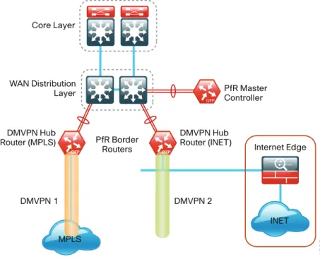
Cisco PfR consists of border routers (BRs) that connect to the DMVPN overlay networks for each carrier network and a master controller (MC) application process that enforces policy. The BR collects traffic and path information and sends it to the MC at each site. The MC and BR can be configured on separate routers or the same router as shown in the figures below.
Figure 11 - Cisco Performance Routing: Hub location WAN Distribution Layer Core Layer DMVPN 2 1225 DMVPN 1 Internet Edge DMVPN Hub
Router (MPLS) DMVPN HubRouter (INET)
INET PfR Border Routers PfR Master Controller MPLS
Figure 12 - Cisco Performance Routing: Remote site options
1226 MPLS Internet MPLS Internet Border Router Master Controller/ Border Router DMVPN 2 DMVPN 1
Single Router Dual Router
Master Controller/ Border Router
Deploying the Cisco
Intelligent WAN
Overall IWAN Architecture Design Goals
Overlay Transport (DMVPN)
All remote-site traffic must be encrypted when transported over public IP networks such as the Internet. This design also encrypts traffic over private IP networks such as MPLS and 4G LTE. It is recommended that you enable encryption on DMVPN over all paths in order to ensure consistency in data privacy and operations. The use of encryption should not limit the performance or availability of a remote-site application and should be transparent to end users.
IP Routing (EIGRP)
The design has the following IP routing goals:
• Provide optimal routing connectivity from primary WAN-aggregation sites to all remote locations • Isolate WAN routing topology changes from other portions of the network
• Ensure active/standby symmetric routing when multiple paths exist, for ease of troubleshooting and to prevent oversubscription of IP telephony call admission control (CAC) limits
• Provide a solid underlying IP routed topology in order to support the Intelligent Path Control provided by Cisco Performance Routing.
• Provide site-site remote routing via the primary WAN-aggregation site (hub-and-spoke model) • Permit optimal direct site-site remote routing (spoke-to-spoke model)
• Support IP Multicast sourced from the primary WAN-aggregation site
At the WAN remote sites, there is no local Internet access for web browsing or cloud services. This model is referred to as a centralized Internet model. It is worth noting that sites with Internet/DMVPN could potentially provide local Internet capability; however, for this design, only encrypted traffic to other DMVPN sites is permitted to use the Internet link. In the centralized Internet model, a default route is advertised to the WAN remote sites in addition to the internal routes from the data center and campus.
The use of local Internet access is covered separately from this guide.
The network must tolerate single failure conditions including the failure of any single WAN transport link or any single network device at the primary WAN-aggregation site.
Quality of Service
The network must ensure that business applications perform across the WAN during times of network
congestion. Traffic must be classified and queued and the WAN connection must be shaped to operate within the capabilities of the connection. When the WAN design uses a service provider offering with QoS, the WAN edge QoS classification and treatment must align to the service provider in order to ensure consistent end-to-end QoS treatment of traffic.
Path Optimization (Performance Routing)
The network must protect business critical applications from fluctuating WAN performance by using the best-performing path based on the application policy. The design must also intelligently load-balance traffic in order to reduce an organization’s overall communications expenses by allowing them to use a less expensive Internet transport without negatively affecting their mission critical traffic.
Remote sites classified as single-router, dual-link must be able tolerate the loss of either WAN transport. Remote sites classified as dual-router, dual-link must be able to tolerate the loss of either an edge router or a WAN transport.
LAN Access
All remote sites support both wired and wireless LAN access.
Design Parameters
This design guide uses certain standard design parameters and references various network infrastructure services that are not located within the WAN. These parameters are listed in the following table.
Table 6 - Universal design parameters
Network service IP address
Domain name cisco.local
Active Directory, DNS server, DHCP server 10.4.48.10 Cisco Secure Access Control System (ACS) 10.4.48.15 Network Time Protocol (NTP) server 10.4.48.17
Deploying the Transport
Independent Design
Design Overview
DMVPN Hub Routers
The most critical devices are the WAN routers that are responsible for reliable IP forwarding and QoS. The amount of bandwidth required at each site determines which model of router to use. The IWAN Hybrid and Dual Internet designs both require dual WAN aggregation routers to support the pair of DMVPN clouds that are required in order to provide resilient connections to all of the remote sites.
Cisco ASR 1000 Series Aggregation Services Routers represent the next-generation, modular, services-integrated Cisco routing platform. They are specifically designed for WAN aggregation, with the flexibility to support a wide range of 3- to 16-mpps (millions of packets per second) packet-forwarding capabilities, 2.5- to 200-Gbps system bandwidth performance, and scaling.
The Cisco ASR 1000 Series is fully modular from both hardware and software perspectives, and the routers have all the elements of a true carrier-class routing product that serves both enterprise and service-provider networks.
This design uses the following routers as DMVPN hub routers:
• Cisco ASR 1002-X router configured with an embedded services processor (ESP) default bandwidth of 5 Gbps upgradable with software licensing options to 10 Gbps, 20 Gbps and 36 Gbps.
• Cisco 4451X Integrated Services Router
Remote Sites—DMVPN Spoke Router Selection
The actual WAN remote-site routing platforms remain unspecified because the specification is tied closely to the bandwidth required for a location and the potential requirement for the use of service module slots. The ability to implement this solution with a variety of potential router choices is one of the benefits of a modular design approach.
There are many factors to consider in the selection of the WAN remote-site routers. Among those, and key to the initial deployment, is the ability to process the expected amount and type of traffic. You also need to make sure that you have enough interfaces, enough module slots, and a properly licensed Cisco IOS Software image that supports the set of features that is required by the topology.
The DMVPN spoke routers at the WAN remote sites connect to the Internet directly through a router interface. More details about the security configuration of the remote-site routers connected to the Internet are discussed later in this guide. The single link DMVPN remote site is the most basic of building blocks for any remote location. This design can be used with the DMVPN spoke router connected directly to the access layer, or it can support a more complex LAN topology by connecting the DMVPN spoke router directly to a distribution layer.
The IP routing is straightforward and can be handled entirely by static routes at the WAN-aggregation site and static default routes at the remote site. However, there is significant value to configuring this type of site with dynamic routing. It is easy to add or modify IP networks at the remote site when using dynamic routing because any changes are immediately propagated to the rest of the network. It is also easier to migrate to a full dual link IWAN design if DMVPN with dynamic routing is already enabled at single link sites.
Figure 13 - IWAN remote-site single-link (basic)
Internet/MPLS DMVPN
1227
The first DMVPN connection is the primary WAN transport. You can add the second DMVPN link to an existing DMVPN single-link design in order to provide the resilient either connecting on the same router or on an additional router. By adding an additional link, you provide the first level of high availability for the remote site. A failure in the primary link can be automatically detected by the router and traffic can be rerouted to the secondary path. It is mandatory to run dynamic routing when there are multiple paths. The routing protocols are tuned to ensure the proper path selection.
The dual-router, dual-link design continues to improve upon the level of high availability for the site. This design can tolerate the loss of the primary router and traffic can be rerouted via the secondary router (through the alternate path).
Figure 14 - IWAN remote-site dual-link
Internet MPLS/ Internet DMVPN-1 DMVPN-2 DMVPN-1 Internet DMVPN-2 1228 MPLS/ Internet
VRFs and Front Door VRF
Virtual route forwarding (VRF) is a technology used in computer networks that allows multiple instances of a routing table to co-exist within the same router at the same time. Because the routing instances are independent, you can use the same or overlapping IP Addresses without conflicting with each other. Often in an L3 VPN context, VRF is also defined as VPN Route Forwarding.
IWAN uses VRF to provide the following:
• Default route separation between user traffic and DMVPN tunnel establishment
• Control and data plane separation between inside and outside networks for security purposes You can implement VRF in a network device by having distinct routing tables, also known as Forwarding Information Bases (FIBs), one per VRF.
The simplest form of VRF implementation is VRF Lite. In this implementation, each router within the network participates in the virtual routing environment on a peer-by-peer basis. VRF Lite configurations are only locally significant.
The IP routing policy used in this design guide for the WAN remote sites does not allow direct Internet access for web browsing or other uses; any remote-site hosts that access the Internet must do so via the Internet edge at the primary site. The end hosts require a default route for all external and Internet destinations; however, this route must force traffic across the primary or secondary WAN transport DMVPN tunnels. DMVPN also has a default route requirement to establish tunnels between sites. The default route for the user traffic over DMVPN conflicts with the default route needed for DMVPN in order to establish tunnels between sites.
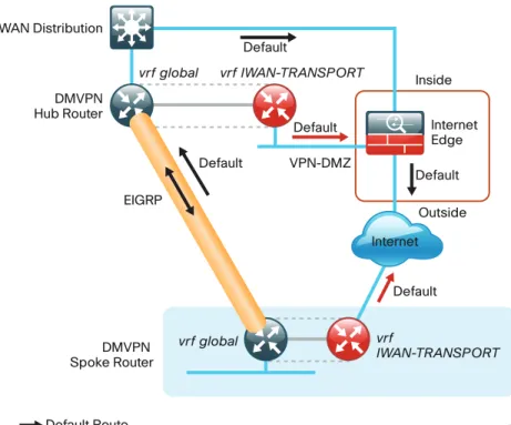
The multiple default route conundrum is solved through the use of VRFs on the router. A router can have multiple routing tables that are kept logically separate on the device. This separation is similar to a virtual router from the forwarding plane perspective. The global VRF corresponds to the traditional routing table, and additional VRFs are given names and route descriptors (RDs). Certain features on the router are VRF aware, including static routing and routing protocols, interface forwarding and IPSec tunneling. This set of features is used in conjunction with DMVPN to permit the use of multiple default routes for both the DMVPN hub routers and DMVPN spoke routers. This design uses global VRF for user traffic routing and a VRF for each WAN physical interface for DMVPN tunnel establishment. This combination of features is referred to as FVRF, because the VRF faces the WAN and the router internal LAN and DMVPN tunnel interfaces all remain in the global VRF. For more technical details regarding FVRF, see “Appendix B: Technical Feature Supplement.”
Figure 15 - Front door VRF (FVRF)
1229 Inside Outside Internet Edge Default Default Default VPN-DMZ Default Default Default Route DMVPN Hub Router WAN Distribution vrf global vrf IWAN-TRANSPORT vrf global vrf IWAN-TRANSPORT
Default Route (vrf IWAN-TRANSPORT) DMVPN
Spoke Router
Internet EIGRP
Design Details
In both the IWAN Hybrid and IWAN Dual Internet design models, the DMVPN hub routers must have sufficient IP-routing information in order to provide end-to-end reachability. Maintaining this routing information typically requires a routing protocol, and EIGRP or BGP are recommended for this purpose. However, a single end-to-end process named IWAN-EIGRP is used in this design guide for the WAN. You can also use Internal BGP (IBGP) as an overlay routing protocol and design guidance for IBGP will be added in the future.
At the WAN-aggregation site, you must connect the DMVPN hub routers to the WAN and configure default routing to build the DMVPN tunnels. The MPLS VPN hub uses default routing to the MPLS provider edge (PE) router, and the Internet VPN hubs use default routing to the DMZ-VPN that provides Internet connectivity. The DMVPN hub routers use FVRF and have a static default route with the IWAN-TRANSPORT VRF pointing to their respective next hops.
Figure 16 - IWAN hybrid design model: FVRF default routing
1231 Distribution Layer Internet Edge Internet A Internet B VPN Hub Router vrf IWAN-TRANSPORT-2 vrf IWAN-TRANSPORT-1 Default Default MPLS CE Router
Default Route (vrf IWAN-TRANSPORT-1) Default Route (vrf IWAN-TRANSPORT-2)
Figure 17 - IWAN dual Internet design model: FVRF default routing
1232 Distribution Layer Internet Edge Internet A Internet B VPN Hub Routers vrf IWAN-TRANSPORT-4 vrf IWAN-TRANSPORT-3 Default
Default Route (vrf IWAN-TRANSPORT-3) Default Route (vrf IWAN-TRANSPORT-4)
EIGRP
Cisco uses EIGRP as the primary routing protocol because it is easy to configure, does not require a large amount of planning, has flexible summarization and filtering, and can scale to large networks. As networks grow, the number of IP prefixes or routes in the routing tables grows as well. You should program IP summarization on links where logical boundaries exist, like distribution layer links to the wide area or to a core. By performing IP summarization, you can reduce the amount of bandwidth, processor, and memory necessary to carry large route tables, as well as reduce convergence time associated with a link failure.
With the advances in EIGRP, this guide uses EIGRP named mode. The use of named mode EIGRP allows related EIGRP configurations to be centrally located in the configuration. Named mode EIGRP includes features such as wide metrics, supporting larger multi-gigabit links. For added security, EIGRP neighbor authentication has been implemented to prevent unauthorized neighbor associations.
With EIGRP named mode configuration, EIGRP Wide Metric support is on by default and backward compatible with existing routes.
Tech Tip
In this design, the primary EIGRP process (AS 400) is referred to as IWAN-EIGRP and uses EIGRP named configuration.
The IWAN-EIGRP process is configured in the WAN-aggregation site in order to connect to the primary site LAN distribution layer, across the DMVPN tunnels and at all WAN remote sites, including those with distribution-layer LAN topologies.
Encryption
The primary goal of encryption is to provide data confidentiality, integrity, and authenticity by encrypting IP packets as the data travels across a network.
The encrypted payloads are then encapsulated with a new header (or multiple headers) and transmitted across the network. The additional headers introduce a certain amount of overhead to the overall packet length. The following table highlights the packet overhead associated with encryption based on the additional headers required for various combinations of IPsec and GRE.
Table 7 - Overhead associated with IPsec and GRE
Encapsulation Overhead
GRE only 24 bytes
IPsec (Transport Mode) 36 bytes IPsec (Tunnel Mode) 52 bytes IPsec (Transport Mode) + GRE 60 bytes IPsec (Tunnel Mode) + GRE 76 bytes
There is a maximum transmission unit (MTU) parameter for every link in an IP network and typically the MTU is 1500 bytes. IP packets larger than 1500 bytes must be fragmented when transmitted across these links. Fragmentation is not desirable and can impact network performance. To avoid fragmentation, the original packet size plus overhead must be 1500 bytes or less, which means that the sender must reduce the original packet size. To account for other potential overhead, Cisco recommends that you configure tunnel interfaces with a 1400 byte MTU.
There are dynamic methods for network clients to discover the path MTU, which allow the clients to reduce the size of packets they transmit. However, in many cases, these dynamic methods are unsuccessful, typically because security devices filter the necessary discovery traffic. This failure to discover the path MTU drives the need for a method that can reliably inform network clients of the appropriate packet size. The solution is to implement the ip tcp adjust mss [size] command on the WAN routers, which influences the TCP maximum segment size (MSS) value reported by end hosts.
The MSS defines the maximum amount of data that a host is willing to accept in a single TCP/IP datagram. The MSS value is sent as a TCP header option only in TCP SYN segments. Each side of a TCP connection reports its MSS value to the other side. The sending host is required to limit the size of data in a single TCP segment to a value less than or equal to the MSS reported by the receiving host.
The IP and TCP headers combine for 40 bytes of overhead, so the typical MSS value reported by network clients will be 1460. This design includes encrypted tunnels with a 1400 byte MTU, so the MSS used by endpoints should be configured to be 1360 to minimize any impact of fragmentation. In this solution, you implement the ip tcp adjust mss 1360 command on all WAN facing router interfaces.
IPsec security association (SA) anti-replay is a security service in which the decrypting router can reject
duplicate packets and protect itself against replay attacks. Cisco QoS gives priority to high-priority packets. This prioritization may cause some low-priority packets to be discarded. Cisco IOS provides anti-replay protection against an attacker duplicating encrypted packets. By expanding the IPsec anti-replay window you can allow the router to keep track of more than the default of 64 packets. In this solution you implement the crypto ipsec security-association replay window-size command in order to increase the window size on all DMVPN routers. IPsec uses a key exchange between the routers in order to encrypt/decrypt the traffic. You can exchange these keys by using a simple pre-sharing algorithm or a certificate authority. You can deploy IOS-CA in order to enroll, store, authenticate and distribute the keys to routers that request them. If a certificate authority is chosen, the certificates and keys can be distributed using the simple certificate enrollment protocol (SCEP) for automated certificate retrieval by the routers.
DMVPN
To address data security and privacy concerns, all IWAN traffic will be encrypted over DMVPN.
All use cases in the Cisco IWAN design are dual-link. The dual-link use cases require a DMVPN dual-cloud design, each with a single hub router. Multiple DMVPN hub routers are supported, but the current version of PfR supports only a single hub router per link. The DMVPN routers use tunnel interfaces that support IP unicast as well as IP multicast and broadcast traffic, including the use of dynamic routing protocols. After the initial spoke-to-hub tunnel is active, it is possible to create dynamic spoke-to-spoke tunnels when site-to-site IP traffic flows require it.
The information required by a spoke to set up dynamic spoke-to-spoke tunnels and properly resolve other spokes is provided through the next-hop resolution protocol (NHRP) within DMVPN. Spoke-to-spoke tunnels allow for the optimal routing of traffic between locations without indirect forwarding through the hub. Idle spoke-to-spoke tunnels gracefully time out after a period of inactivity.
It is common for a firewall to be placed between the DMVPN hub routers and the Internet. In many cases, the firewall may provide NAT from an internal RFC-1918 IP address (such as 192.168.146.10) to an Internet-routable IP address. The DMVPN solution works well with NAT but requires the use of IPsec transport mode to support a DMVPN hub behind static NAT.
The IWAN DMVPN design requires the use of Internet Key Management Protocol version 2 (IKEv2) keepalive intervals for dead peer detection (DPD), which is essential to facilitate fast reconvergence and for spoke
registration to function properly in case a DMVPN hub is restarted. This design enables a spoke to detect that an encryption peer has failed and that the IKEv2 session with that peer is stale, which then allows a new one to be created.
Without DPD, the IPsec security association (SA) must time out (the default is 60 minutes) and when the router cannot renegotiate a new SA, a new IKEv2 session is initiated. The IWAN design with the recommended IKEv2 and DPD timers reduces this convergence time to 40 seconds.
Figure 18 - DMVPN dual-cloud 2158 DMVPN Spoke DMVPN Spoke DMVPN Spoke DMVPN Spoke DMVPN Head End Cloud 1
Hub Cloud 2Hub
DMVPN Head End
DMVPN Spoke
DMVPN Cloud 1 DMVPN Cloud 2
Internet Spoke-Spoke Tunnel
One of the key benefits of the DMVPN solution is that the spoke routers can use dynamically assigned
addresses, often using DHCP from an Internet provider. The spoke routers can leverage an Internet default route for reachability to the hub routers and also other spoke addresses.
The DMVPN hub routers have static IP addresses assigned to their public-facing interfaces. This configuration is essential for proper operation as each of the spoke routers have these IP addresses embedded in their configurations.
Deployment Details
This guide uses the following conventions for commands that you enter at the command-line interface (CLI).
Commands to enter at a CLI prompt:
configure terminal
Commands that specify a value for a variable:
ntp server 10.10.48.17
Commands with variables that you must define:
class-map [highest class name]
Commands at a CLI or script prompt:
Router# enable
Long commands that line wrap are underlined. Enter them as one command:
police rate 10000 pps burst 10000 packets conform-action
Noteworthy parts of system output (or of device configuration files) are highlighted:
interface Vlan64
ip address 10.5.204.5 255.255.255.0
How to Read Commands
The procedures in this section provide examples for most settings. The actual settings and values that you use are determined by your current network configuration.The following optional process is used for both the IWAN hybrid design model and the IWAN dual Internet design model.
Configuring an IOS Certificate Authority
1. Configure the IOS CA platform 2. Configure the WAN-facing VRFs
3. Configure connectivity to the three networks 4. Configure certificate authority
P
RO
C
ES
S
Use this optional process if you want to deploy an IOS Certificate Authority (IOS CA) on a router in your DMZ with access from the internal network and the MPLS provider network. Skip this process if you are using pre-shared keys or if you plan to use a different certificate authority. You can create a more complex CA environment, but the same basic reachability principles will apply for an IWAN enabled solution.
For this process, you configure an IOS CA with three interfaces:
• The first interface on the internal LAN allows access from the hub routers and is also used for managing the router.
• The second interface on the DMZ allows access from remote site routers with Internet connectivity. • The third interface on the MPLS provider network allows access from remote site routers with MPLS
Each interface is in its own VRF and there is no routing between the interfaces. Three static routes allow the IOS CA to reach each network individually.
Figure 19 - IOS CA with three non-routed interfaces
WAN Distribution Layer Core Layer DMVPN 2 1233 MPLS DMVPN 1 Internet Edge DMVPN Hub
Router (MPLS) DMVPN HubRouter (INET)
INET IOS-CA #1
#2 #3
Procedure 1 Configure the IOS CA platform
Step 1: Configure the device host name. Make it easy to identify the device.
hostname IWAN-IOS-CA
Step 2: Configure the local login and password.
The local login account and password provides basic access authentication to a router that provides only limited operational privileges. The enable password secures access to the device configuration mode. By enabling password encryption, you prevent the disclosure of plain text passwords when viewing configuration files.
username admin secret c1sco123
enable secret c1sco123
service password-encryption aaa new-model
By default, https access to the router uses the enable password for authentication. Step 3: (Optional) Configure centralized user authentication.
As networks scale in the number of devices to maintain, it poses an operational burden to maintain local user accounts on every device. A centralized authentication, authorization and accounting (AAA) service reduces operational tasks per device and provides an audit log of user access for security compliance and root cause analysis. When AAA is enabled for access control, AAA controls all management access to the network infrastructure devices (secure shell [SSH] and hypertext transfer protocol secure [HTTPS]).
Terminal access controller access control system plus (TACACS+) is the primary protocol used to authenticate management logins on the infrastructure devices to the AAA server. A local AAA user database is also defined (in Step 2) on each network infrastructure device in order to provide a fallback authentication source in case the centralized TACACS+ server is unavailable.
tacacs server TACACS-SERVER-1
address ipv4 10.4.48.15
key SecretKey
aaa group server tacacs+ TACACS-SERVERS
server name TACACS-SERVER-1
aaa authentication login default group TACACS-SERVERS local aaa authorization exec default group TACACS-SERVERS local aaa authorization console
ip http authentication aaa
Step 4: Configure device management protocols.
HTTPS and SSH are secure replacements for the HTTP and Telnet protocols. They use secure sockets layer (SSL) and TLS in order to provide device authentication and data encryption.
Secure management of the network device is enabled through the use of the SSH and HTTPS protocols. Both protocols are encrypted for privacy and Telnet is turned off. SCP is enabled, which allows the use of code upgrades using Prime Infrastructure via SSH based SCP protocol. HTTP is needed for SCEP and CRL download. Specify the transport preferred none on vty lines to prevent errant connection attempts from the CLI prompt. Without this command, if the ip name-server is unreachable, long timeout delays may occur for mistyped commands. ip domain-name cisco.local ip ssh version 2 ip http server ip http secure-server ip scp server enable line vty 0 15 transport input ssh transport preferred none
When synchronous logging of unsolicited messages and debug output is turned on, console log messages are displayed on the console after interactive CLI output is displayed or printed. With this command, you can continue typing at the device console when debugging is enabled.
line con 0
transport preferred none logging synchronous
Enable SNMP in order to allow the network infrastructure devices to be managed by a NMS. SNMPv2c is configured both for a read-only and a read-write community string.
snmp-server community cisco RO snmp-server community cisco123 RW
snmp-server ifindex persist ! IOS Classic Only snmp ifmib ifindex persist ! IOS XE Only
Step 5: (Optional) In networks where network operational support is centralized, you can increase network security by using an access list to limit the networks that can access your device. In this example, only devices on the 10.4.48.0/24 network will be able to access the device via SSH or SNMP.
access-list 55 permit 10.4.48.0 0.0.0.255
line vty 0 15 access-class 55 in
snmp-server community cisco RO 55
snmp-server community cisco123 RW 55
snmp-server ifindex persist ! IOS Classic Only snmp ifmib ifindex persist ! IOS XE Only
If you configure an access-list on the vty interface you may lose the ability to use ssh to login from one router to the next for hop-by-hop troubleshooting.
Tech Tip
Step 6: Configure a synchronized clock.
The network time protocol (NTP) is designed to synchronize a network of devices. An NTP network usually gets its time from an authoritative time source, such as a radio clock or an atomic clock attached to a time server. NTP then distributes this time across the organizations network.
A synchronized clock is an absolute requirement for routers using certificates, since certificates have a valid lifetime. The local NTP server typically references a more accurate clock feed from an outside source. By configuring console messages, logs, and debug output to provide time stamps on output, you can cross-reference events in a network.
ntp server 10.4.48.17
clock timezone PST -8
clock summer-time PDT recurring
service timestamps debug datetime msec localtime service timestamps log datetime msec localtime
Procedure 2 Configure the WAN-facing VRFs
The VRF name is arbitrary, but it is useful to select a name that describes the VRF. The VRF must be enabled for IPv4.
This design uses VRF Lite, so the selection is only locally significant to the device. It is a best practice to use the same VRF/RD combination across multiple devices when using VRFs in a similar manner. However, this convention is not strictly required.
Example: DMZ facing VRF (public Internet)
vrf definition IWAN-PUBLIC
description IWAN PUBLIC (Internet DMZ)
address-family ipv4
Example: MPLS facing VRF (MPLS provider)
vrf definition IWAN-TRANSPORT-1
description IWAN TRANSPORT 1 (MPLS)
address-family ipv4
Procedure 3 Configure connectivity to the three networks
Each interface is in its own VRF and there is no routing between the interfaces. Three static routes allow the IOS CA to reach each network individually.
Table 8 - IOS CA IP address assignments
Network IP Address NAT IP Address
Internal 10.6.24.11 N/A
Internet DMZ 192.168.144.127 172.16.140.110 (ISP-A)
MPLS Provider 192.168.6.254 N/A
The NAT IP address is added in the “Configuring the Firewall and DMZ Switch” process later in this guide. Step 1: The internal address is an inside address that can be accessed from the hub site or a remote site if the site is already up and running with a DMVPN tunnel.
interface GigabitEthernet0/0
description Internal
ip address 10.6.24.11 255.255.255.224
no shutdown
Step 2: The second interface is connected to the DMZ network. This address is only reachable from the IWAN-PUBLIC VFR and has NAT applied in order to be addressable via the Internet.
interface GigabitEthernet0/1
description Internet DMZ
vrf forwarding IWAN-PUBLIC
ip address 192.168.144.127 255.255.255.0
no shutdown
Step 3: The third interface is connected to the MPLS provider network. This address is reachable from the IWAN-TRANPORT-1 VRF at a remote site before there is a DMVPN tunnel.
interface GigabitEthernet0/2
description MPLS Provider
vrf forwarding IWAN-TRANSPORT-1
ip address 192.168.6.254 255.255.255.252
Step 4: Configure IP routing using static routes.
Three static routes are configured. The first default static route is for traffic into the internal LAN. The second default static route is for the VRF IWAN-PUBLIC towards the Internet and the third default static route is for VRF IWAN-TRANSPORT-1 towards the MPLS provider.
ip route 0.0.0.0 0.0.0.0 10.6.24.1
ip route vrf IWAN-PUBLIC 0.0.0.0 0.0.0.0 192.168.144.1
ip route vrf IWAN-TRANSPORT-1 0.0.0.0 0.0.0.0 192.168.6.253
Procedure 4 Configure certificate authority
The following commands configure the certificate authority (CA) on the router. This CA can be part of a public key infrastructure (PKI) hierarchy, but only of IOS authorities, and the certificate from the root CA must be issued via SCEP.
Step 1: Configure the server.
crypto pki server IWAN-IOS-CA
database level complete no database archive
issuer-name CN=IWAN-IOS-CA.cisco.local L=SanJose St=CA C=US
Step 2: Configure the server to use SCEP for issuing certificates.
grant auto
Step 3: Configure the lifetime for the issued certificates at 2 years. The time is in days.
lifetime certificate 730
Step 4: Configure the lifetime for the certificate server signing certificate at 3 years. The time is in days.
lifetime ca-certificate 1095
Step 5: Configure the location for certificate revocation lists.
In order to force the parser to retain the embedded question mark within the specified location, enter CTRL+V prior to the question mark. If this action is not taken, CRL retrieval through HTTP returns an error message.
Tech Tip
cdp-url http://10.6.24.11/cgi-bin/pkiclient.exe?operation=GetCRL