Inside Rotor Brushless Motors Outside Rotor Brushless Motors Direct Drive Brushless Motors Brush Motors Position Sensors Drive Electronics Gearheads Integrated Mechanisms Application Information Standard Motor Options
Synchro TypeS
Transmitter
The synchro transmitter (CG) consists of a single-phase, salient-pole (dumbbell-shaped) rotor and a three-phase, Y-connected stator.* The primary or input winding is usually the rotor; the stator is usually the secondary or output element. The rotor is excited through a pair of slip
rings with an AC voltage. The field produced by the input voltage induces
a voltage into each of the stator phases. The magnitude of the induced
phase-voltage depends on the angle between the rotor field and the
resultant axis of the coils forming that stator phase. Since the axes of the three stator phases are 120° apart, the magnitudes of the stator output voltages can be written as:
Vs1-3=k Vr2-1 sinθ
Vs3-2=k Vr2-1 sin (θ+120)
Vs2-1=k Vr2-1 sin (θ+240) • Where k is the maximum coupling transformation ratio (TR)
• Which is further defined as TR=Vout (max.) and is a scalar quantity.
Vin
• θ is the rotor position angle.
• Vs1-3 is the voltage from the S1 terminal to the S3 terminal, and all other voltages are similarly defined here and throughout this
discussion.
These stator voltages are either approximately in time-phase or approximately 180° out-of-time-phase with the applied voltage. The amount by which the output voltages differ from the exact 0° or 180°
time-phase relationship with the input voltage is known as the synchro (time) phase shift. For a synchro operated at 400 Hz working into an open circuit,
the output voltage will always lead the input voltage by a few degrees (8° to 20° for small sizes; 2° to 8° for larger sizes).
From the above transmitter equations it can readily be seen that nowhere
over the entire 360° rotation of the rotor will the same set of stator voltages appear. The transmitter thus supplies information about the rotor position
angle as a set of three output voltages. To make use of this information, however, it is necessary to find an instrument which will measure the
magnitude of these voltages, examine their time-phase relationships and return them to their original form – a shaft position. Such an instrument
is the synchro receiver (CR). These two units – the transmitter and the
receiver – form the most basic synchro system.
Receiver
In construction, the receiver is electrically identical to the transmitter. The output voltages vary with rotor position in the identical manner as
that given for the transmitter. In use, the receiver is connected back-to-back with a transmitter; i.e., like-numbered terminals are connected
together (See Figure 1) and the rotors are excited in parallel. At the instant the system is energized, if the rotors of each unit are not at the exact same angle relative to the stator phases, voltage differences
exist across each pair of stator windings causing current to flow in both stators. This stator current produces a torque on each rotor.
FIGUre 1
Since the CG rotor is constrained from turning, the resultant torque acts on the CR rotor in such a direction as to align itself with the transmitter. When alignment occurs, the voltages at each stator terminal are equal and opposite, and no current flows. Perfect synchronization is never achieved
in practice because of the internal friction (due to bearings and brushes)
of the receiver. To minimize this error, the receiver is designed to have a Note: Moog Components Group product lines. With respect to the U.S. export regulations, the This catalog contains basic marketing information and general part descriptions of
Synchro
Application Guide
Synchro Fundamentals
As a circuit element, the synchro is essentially a
variable-coupling transformer; the magnitude of the magnetic
coupling between the primary and secondary, and hence
the magnitude of the output voltage, varies according
to the position of the rotatable element. In function,
the synchro is an electromechanical transducer. A
mechanical input such as a shaft rotation is converted to
a unique set of output voltages, or a set of input voltages
is used to turn a synchro rotor to a desired position.
Synchros can be classified in two overlapping groups:
torque synchros and control synchros.
Torque synchros include transmitters (CG), differentials
(CD) and receivers (CR).
Control synchros include transmitters (CG), differentials
(CD) control transformers (CT), resolvers (CS), linear
transformers (LT) and the two hybrid units: transolvers
(CSD) and differential resolvers (CDS).
*Note: the use of the word “phase” will always indicate a space-phase relationship,
Inside Rotor Brushless Motors Outside Rotor Brushless Motors Direct Drive Brushless Motors Brush Motors Position Sensors Drive Electronics Gearheads Integrated Mechanisms Application Information Standard Motor Options
Synchro Application Guide
receiver and is especially constructed with an extremely low starting friction (5000 mg-mm) to minimize system errors. An accuracy of 1° is standard.
All synchro systems are subject to one serious drawback – torque levels
typically run around 3000 mg-mm per degree of receiver displacement. This
is sufficient to turn a dial or a pointer but nothing larger without increasing system errors. When higher torques are required, synchros are used to control other devices which will provide these torques. An integral part of
these control systems is the synchro control transformer. (CT).
Control Transformer
The CT consists of a three-phase, Y-connected stator and a single-phase drum (cylindrical) rotor. In normal usage, the stator is the primary element, the rotor is the secondary, and the unit is connected as shown in Figure 4. From the schematic of Figure 4, it can be seen that the transmitter sets up a
voltage field in the CT stator whose direction is exactly that of the transmitter
and whose magnitude is directly proportional. As the transmitter rotor turns
with the CT rotor stationary, the magnitude of the CT stator field remains constant, and its direction exactly matches that of the transmitter. The field
cutting across the CT rotor induces a voltage in the rotor. The magnitude of this voltage depends on the sine of the angle between the axis of the rotor
winding and the stator flux vector; the time phase of the CT output voltage
is either approximately in time-phase or 180° out-of-time-phase with the exciting voltage on the transmitter rotor. Since the angle of the CT stator
flux field depends upon the transmitter rotor angle, the CT output voltage
can be used to obtain information about the transmitter rotor angle.
FIGUre 4
The basic CG-CT control system is shown in Figure 5.
FIGUre 5
If the CT rotor angle is not the same as that of the transmitter, a voltage proportional to the sine of the angular difference appears on the CT rotor.
This voltage is impressed across the input of a servo amplifier, which, in
turn, is connected to the control phase of a servomotor. The motor, which is
geared back to the CT rotor shaft, will turn to oppose the voltage causing its
motion. It will rotate until the CT rotor is at the same angle as the CG rotor; at this position, the CT output voltage is theoretically zero and motion will
cease. With additional gearing the synchro motor provides a mechanical output for other useful work. This synchro system, which develops no torque of it own, acts as the control device which moves high torque loads. The accuracy of the entire system depends on synchro error, amplifier gain, servo
response, and gearing errors. Using standard components, the synchro
system error is usually specified as 10 arc minutes maximum; by selecting
synchros or by trimming, this error can be reduced well below the given
figure. If multispeed pancake synchros are used, accuracies measured in
seconds of arc are standard.
Turning the transmitter rotor from the equilibrium position will again exert
a force on the receiver rotor. As soon as this developed force exceeds the
internal friction of the receiver, the CR will track the CG to its new position. The torque developed on the receiver shaft is proportional to the angle between the two rotors and is usually expressed in mg-mm/deg. Methods for measuring the torque produced by a transmitter-receiver pair are to be found in Society of Automotive Engineers Specification ARP-461. Receivers are constructed to minimize oscillations and overshoot or spinning when the rotor is turning to a new position. The time required for
the rotor to reach and stabilize at its new rest position is called the damping or synchronizing time. This time varies with the size of the receiver, the
inertia of the load, and the system torque. By special receiver construction, the damping time can be reduced if required by system considerations. The CG-CR system is used to transmit angular information from one point to another without mechanical linkages. The standard transmission
accuracy for such a system is 30 arc minutes. The information can be sent to more than one location by paralleling more than one receiver across the transmitter. The more receivers used, however, the less accurate the system, and the larger the power draw from the source.
Differential
A third type of synchro may be added to our basic torque system – the
differential (CD). The differential stator is three-phase, Y-connected and is usually the primary element; the rotor is cylindrical and is also wound with three Y-connected phases. The output voltages of the CD depend not only on the input voltages but also on the rotor shaft position.
As shown in figure 2, the differential stator is normally excited from a
transmitter stator, and the differential rotor is connected to the receiver stator. The output voltages of the differential are dependent now on both the transmitter rotor position (θCG) and its own rotor position (θCD).
The receiver rotor will seek a position (θCR) which is either the sum or difference of the transmitter and differential rotor angles (θCR = θCG ± θCD), depending on how the CG and CD stators are interconnected.
θ CG θ CD θ CR FIGUre 2 θ 1 θ CD θ 2 FIGUre 3
The differential may also be energized between two transmitters as shown in Figure 3. In this system, each transmitter is turned to its desired angle, and the differential rotor is forced to assume a position which is either the sum or the difference of the angles between the transmitter rotors (θCD = θ1
Inside Rotor Brushless Motors Outside Rotor Brushless Motors Direct Drive Brushless Motors Brush Motors Position Sensors Drive Electronics Gearheads Integrated Mechanisms Application Information Standard Motor Options
another is desired. Spacecraft and aircraft often require the craft’s pitch, roll and yaw to be transformed back to earth references. One resolver
is needed to provide two-axis transformation; three resolvers, to provide three-axis transformation.
FIGUre 6
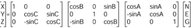
Figure 6 schematically represents the interconnections of three resolvers necessary to transform from inertial platform coordinates (N,E,G) to an
airborne vehicle’s coordinates (X,Y,Z). This resolver chain essentially solves the matrix equation:
Resolver chains are commonly used to solve trigonometric problems of
varying degrees of complexity. The resolvers in this application are specially
designed to work with a buffer, booster, or feedback amplifier and they are known as feedback or compensated resolvers (CQ or CY). The rotor of a
compensated resolver is identical to that of a standard resolver; however,
the stator has two additional sets of coils called the compensator or feedback
winding. The compensator winding is laid in the same slots as the stator
winding. Practically all the flux generated by the stator exciting current links all the turns of the compensator, so that the compensator output is essentially equal to the input voltage, and is naturally constant with rotor
position. The time phase shift of the rotor output voltage of the compensator voltage is identical with the time phase shift of the rotor output voltage,
since both voltages were induced by the stator flux field. Because of the resolver’s construction, any change in the stator flux due to temperature
or voltage immediately produces a change in the compensator voltage.
The negative feedback through the amplifier restores the stator field to its original conditions. A resolver-amplifier pair is thus basically error-free, with
respect to resolver chain performance, over a wide range of environmental conditions.
FIGUre 7
Resolvers also are used in time-phase-shifting applications. A typical con -nection for a resolver phase shifter is shown in Figure 7. The resistance
R is chosen to match the reactance of the capacitor C at the operating frequency, and both R and XC are substantially higher than the resolver
output short circuit impedance. Under proper operating conditions, the phase shifter output is:
Vout = k Vin ∠θ
Note that the output voltage is constant with rotor position, but the time
phase shift in electrical degrees between the output and the input is equal to the rotor position angle in mechanical degrees. Using a balanced R-C network and a stable frequency source, standard resolvers can be used
as phase shifters with an accuracy of ±¼° or better.
Synchro Application Guide
In some systems, a control transformer is made to act, through switching circuits, as both a transmitter and a CT. This practice is not recommended.
Because of its impedance levels and its cylindrical, distributed-winding
rotor, the CT can never act as a transmitter without causing degradation
in system accuracy and system null voltage. Whenever a synchro must
serve as both a CG and a CT, we recommend the use of a transolver (CSD)
Transolver, Differential Resolver
The transolver is essentially a control transformer with a second rotor
winding wound in space quadrature to the main winding. When used as CT, the transolver’s second rotor winding is dummy-loaded symmetrically with the main winding to avoid unbalances. When using the transolver as
a transmitter, the unused rotor winding is shorted to ground, thus providing electrical saliency and permitting the transolver to operate as a transmitter without introducing additional errors. The differential resolver (CDS) is the inverse of the transolver (i.e., the rotor is the three-phase element, the stator is two-phase). In function, the transolver and differential resolver are identical. The advantage of the differential resolver over the transolver lies in those applications where four-wire outputs are desired; it is more economical to bring out four stator leads than to provide four rotor slip rings
and four sets of brushes. Both the transolver and the differential resolver find considerable usage in systems where it is desirable to convert
three-wire data into four-three-wire data. These units form the bridge between the three-phase devices – transmitters, receivers, differentials, and control transformers – and the two-phase units, or resolvers.
Resolver
The resolver (CS) consists of a cylindrical rotor with two phases wound in
space quadrature and a stator also with two quadrature phases. In standard
resolvers (CS), the ends of the rotor phases are internally connected and brought out with a common lead. A resolver with all four rotor leads brought
out separately is designated by CZ. The classic function of a resolver, as
the name implies, is to resolve a vector into its components. Energizing
one phase of the input element – either rotor or stator – with a voltage V
induces a voltage into one output winding whose magnitude varies according to the sine of the rotor position angle θ. The other output winding, being
in space quadrature to the first, must then have an induced voltage whose
magnitude varies as sin (90-θ) or cosθ. The two outputs are thus V sinθ and
V cosθ (assuming a unity transformation ratio), which are the components
of the input vector V.
A resolver which is specifically meant to separate a vector into its
components is the vector resolver (CV or CW). This unit type differs from
the standard resolver because the rotor is wound with only one phase.
The vector resolution is reversible because if two voltages, (X and Y),
representing vector components are applied to the inputs of the resolver,
the corresponding polar coordinates, (R, θ), can be obtained. Since the two
inputs are in quadrature, applying voltages X and Y to these inputs will set up a resultant field whose magnitude is √ (X2 + Y2) or R. If one output phase is connected through an amplifier to a servomotor which is geared back to the resolver shaft, the voltage on the other output will be proportional to R,
and the rotor position angle will indicate θ (tan-1 Y/X).
Exciting one input of a resolver with voltage A produces outputs of A sinθ
and A cosθ. Exciting the other input with voltage B produces outputs of B sin
(θ + 90) or B cosθ and B cos (θ - 90) or –B sinθ. Energizing both windings
at once then gives two outputs Y and X whose magnitudes are of the form: Y=A sinθ + B cosθ
X=A cosθ - B sinθ
From analytic geometry, these two equations represent a transformation of axes by rotating without translation; Y and X are the new components obtained by rotating A and B through the angle θ. Resolvers then find
Inside Rotor Brushless Motors Outside Rotor Brushless Motors Direct Drive Brushless Motors Brush Motors Position Sensors Drive Electronics Gearheads Integrated Mechanisms Application Information Standard Motor Options
loads. Severe impedance mismatches may cause sufficient distortion of the voltage waveforms with subsequent loss of accuracy. Our Engineering
Department stands ready to help you with recommendations for proper synchro usage in your applications.
Null Voltage
Theoretically, when a coil is exactly parallel to the direction of a flux field – such as at electrical zero – no flux lines link the turns of this coil and the
voltage induced in it is exactly zero. At any minimum-coupling position, however, there is always some residual voltage. This voltage is called the null voltage.
The null is composed of a fundamental component, which is in time
quadrature with the exciting voltage (the in-time phase component is
always forced to zero), and odd harmonics. The fundamental component is due mainly to winding imperfections and magnetic circuit distortions; the
harmonics, to non-sinusoidal distribution of the air gap flux.
Nulls are measured in accordance with the phase-sensitive voltmeter method of MIL-S-20708E at each synchro minimum-coupling point.
Because of symmetry, each output winding has two null points which are
180° apart, for each input winding. A transmitter has six null points; a resolver, eight; and a differential, eighteen.
Low synchro nulls are essential to proper system performance. Currently, we specify that the maximum null voltage shall not exceed 0.1% of the applied voltage.
Other Electrical Parameters
The remaining electrical tests – transformation ratio, phase shift, DC resistance, input current and power, impedance - are performed in
accordance with applicable industry and military specifications.
Mechanical Parameters
In addition to checking mounting dimensions, our Final Test checks each
synchro for conformance to our shaft end play, shaft radial play, and starting
friction requirements. Shaft end play is the total axial motion of the shaft
when an eight-ounce reversing load is applied along the shaft axis. Shaft radial play is the total side-to-side motion of the shaft measured as close to the bearing as possible, when a four-ounce reversing load is applied radially
to the shaft within ¼ inch of the bearing. Starting friction is the torque
necessary to overcome the internal friction of the bearings and brushes and to commence shaft rotation.
Because of the important relationship between accuracy and shaft end and
radial play, these parameters are controlled as rigidly as possible. If end and radial play are too loose, higher errors and non-repeatability of the calibration pattern result; if they are too tight, performance over environmental service conditions may suffer. Friction, except in receivers, is relatively unimportant.
We currently specify four gram-centimeter maximum friction which has been
found to be an optimum level for operation in both normal and extreme
temperature ambients. On units where lower friction limits are a system requirement, however, we will work with our customers to establish these limits consistent with the end requirement and with good design practices.
For synchro applications where conventional commutation such as slip rings and brushes is either undesirable or unwanted, we has developed several varieties of brushless synchros, for both full rotation and limited rotation.
Electromagnetic Type
In the electromagnetic brushless synchro, energy is transferred from the rotor by means of a circular transformer mounted at the rear of the unit.
BrUShleSS SynchroS
Synchro Application Guide
Resolvers are also used in control systems exactly like those described for
three-phase units. In such applications, the units are sometimes referred to as resolver transmitters, resolver differentials, and resolver control transformers. Their construction is identical to standard resolvers with the exception of the resolver differential, which should have four-wire input and four-wire output. Data transmission by resolvers is usually preferred over three-phase transmission, as resolvers are generally more accurate than their three-phase counterparts.
Linear Transformer
In many resolver circuits involving vector resolution, the input voltage to the
resolver is taken from the output of a linear transformer (LT). The linear
transformer consists of a one-phase, salient-pole rotor and a single-phase
stator. Unlike all other synchros where the output voltage is proportional
to the sine of the rotor position angle, the LT is constructed so that the
output voltage is directly proportional to the angle itself. In equation form:
Vout=k θ (-50°<θ<50°)
The angular band over which the output equation remains valid is known as the excursion range. Beyond the excursion range, the plot of output
voltage against rotor position tends toward a sinusoid. The LT acts as a circuit replacement for a potentiometer with the chief advantages of low
starting friction and infinite resolution over the excursion range. Because of
construction similarities, the LT also matches the performance of resolvers over environmental service conditions.
Accuracy
Of all synchro parameters, accuracy is probably the most important. The synchro is meant to give unique information about the rotor position angle as a set of output voltages. Synchro error is thus defined as the electrical
angle, as indicated by the output voltages, minus the rotor position angle.
Calibration is the process of determining the error at specified angular
intervals for the full 360° rotor travel. The calibration starts at a reference
point called electrical zero (EZ) and defined as a rotor position angle of 0°. The electrical zero point is defined differently for each synchro type, but it always is a rotor position where a specified output winding has minimum voltage induced in it with a specified input winding energized with rated voltage and frequency. During calibration, the units are held and precisely
positioned in an Index Stand. The Index Stand provides a mechanical position that is accurate within ten (10) arc seconds. The calibration itself is
in accordance with the proportional voltage methods of military specifications MIL-S-20708E and MIL-R-23417B.
Synchro accuracy is of necessity a function of the electrical balance of the windings comprising the input and output phases.
Total turns, pitch factors, distribution factors, insertion patterns, winding
integrity must all be in accordance with design requirements if the synchro is to be calibrated within specification limits. Surpassing the electrical
problems, however, are the mechanical ones. Accuracy is to a great extent dependent on mechanical perfection. To obtain proper accuracy, it is extremely important to control eccentricities of the air gap surfaces with respect to the mounting surfaces, roundness of the air gap surfaces, mechanical parallelism and perpendicularity, and the radial and axial
position of the rotor inside the stator. Our long experience in recognizing and
combating these problems insures you of accurate, repeatable synchros. Component accuracy itself, however, is only one part of system accuracy.
When units are cascaded in a synchro chain, unbalances in time phase
shift, transformation ratio, and impedance may far outweigh inherent
unit accuracy in determining system error. A resolver with a five minutes maximum error cannot exhibit that accuracy when working into unbalanced
Inside Rotor Brushless Motors Outside Rotor Brushless Motors Direct Drive Brushless Motors Brush Motors Position Sensors Drive Electronics Gearheads Integrated Mechanisms Application Information Standard Motor Options
Synchro Application Guide
There are no physical connections to the rotor so the life of the unit is limited solely by the life of the bearings. Tens of thousands of hours of operational life at high rotational speeds are easily achievable with this type of unit. The major disadvantage of the electromagnetic brushless synchro is that the dual magnetic structures (synchro and transformer) do not allow the duplication in this design of standard synchro parameters. In general, when compared with a standard unit, the brushless synchro will have higher power consumption, lower impedance angle, higher phase
shift and lower unit torque gradient. This can be a problem if the intent is to
replace a synchro in an existing system. In new applications, the variations in unit performance can be accommodated. Closer conformance to existing synchros can be achieved with additional unit length. In any case,
multi-phase rotors require additional length.
Hairspring Type
Limited rotation units are made with spirally wound conductors used to pick
off information from the rotor. These hairspring conductors allow a rotation of as much as ±165° from the electrical zero position. The units are normally supplied with a mechanical stop to prevent damage to the hairsprings due to excessive shaft rotation. The addition of the stop normally engenders extra length.
The advantage of a hairspring synchro over an electromagnetic brushless synchro is that any standard synchro can be manufactured in a hairspring design with no change in electrical parameters. If the application permits limited rotation, a hairspring unit can replace the conventional unit already
in the system with no effect on system performance except for the benefits attendant on the elimination of sliding contacts. Properly designed
hairsprings, such as ours, will perform millions of operations without failure.
Flex Lead Type
A flex lead brushless synchro is designed with thin flexible lead wires to transfer energy from/to the rotor. These units have all the advantages of
the hairspring type and are used in applications where short unit length and
low friction are required. Rotation is usually limited to ±90°.
To discuss the possibility of the use of a type of brushless unit in your application, contact our Engineering Department.