3 Special
Craft
4
Guidelines for Lifeboats and Rescue Boats
The following Guidelines come into force on November 1
st, 2008
Germanischer Lloyd Aktiengesellschaft
Head Office
Vorsetzen 35, 20459 Hamburg, Germany
Phone: +49 40 36149-0
Fax: +49 40 36149-200
[email protected]
www.gl-group.com
"General Terms and Conditions" of the respective latest edition will be applicable
(see Rules for Classification and Construction, I - Ship Technology, Part 0 - Classification and Surveys).
Reproduction by printing or photostatic means is only permissible with the consent of
Germanischer Lloyd Aktiengesellschaft.
Published by: Germanischer Lloyd Aktiengesellschaft, Hamburg
Printed by: Gebrüder Braasch GmbH, Hamburg
Table of Contents
Section 1 General Requirements
A. General ... 1- 1 B. Definition of Principal Boat Parameters ... 1- 2 C. Ambient Conditions ... 1- 4 D. Principle Design Requirements ... 1- 5
Section 2 Certification Procedure
A. General ... 2- 1 B. Steps of GL Conformity Procedure ... 2- 1 C. GL Acceptance of Approvals by other Societies/Authorities ... 2- 10 D. Periodical Surveys ... 2- 10
Section 3 Buoyancy and Stability
A. General ... 3- 1 B. Buoyancy ... 3- 1 C. Stability ... 3- 1
Section 4 Hull Structures
A. General ... 4- 1 B. Fibre Reinforced Plastics (FRP) Materials ... 4- 1 C. General Practical Approval Tests ... 4- 2 D. Design Loads for Normal Operation ... 4- 2 E. Determination Procedure for FRP Structures ... 4- 2
Section 5 Hull Outfit
A. General ... 5- 1 B. Painting and Marking ... 5- 1 C. Rudder ... 5- 1 D. Manoeuvring Equipment ... 5- 4 E. Release Mechanism ... 5- 6 F. Enclosures ... 5- 7 G. Access to the Lifeboat ... 5- 8 H. Doors, Hatches and Windows ... 5- 9 I. Seating ... 5- 10 J. Lockers and Compartments ... 5- 11 K. Miscellaneous Loose lifeboat equipment ... 5- 11 L. Tests ... 5- 13
Section 6 Fire Protection and Fire Extinguishing Equipment
B. Fire Protection ... 6- 1 D. Tests ... 6- 2
Section 7 Machinery Installations
A. General ... 7- 1 B. Internal Combustion Engines ... 7- 2 C. Power Transmission ... 7- 4 D. Auxiliary Systems ... 7- 6 E. Ventilation ... 7- 9 F. Steering Gear ... 7- 10 G. Tools and Spare Parts ... 7- 11 H. Tests ... 7- 12
Section 8 Electrical Installations
A. General ... 8- 1 B. Power Supply ... 8- 1 C. Distribution System ... 8- 2 D. Consumers ... 8- 3 E. Spare Parts ... 8- 4 F. Tests ... 8- 4
Section 9 Special Requirements for Lifeboats used as Tenders
A. General ... 9- 1 B. Lifeboat Service ... 9- 1 C. Tender Service ... 9- 1
Section 10 Special Requirements for Rescue Boats and Fast Rescue Boats
A. General ... 10- 1 B. Requirements for the Design ... 10- 1 C. Rescue Boat Equipment ... 10- 2 D. Additional Requirements for Inflated Rescue Boats ... 10- 3 E. Additional Requirements for Fast Rescue Boats ... 10- 4 F. Tests ... 10- 5
Section 11 Tests for Lifeboats and Rescue Boats
Index
A
Access ... 1-5, 5-8 Air cooling system ... 7-8 Ambient Conditions ... 1-4 Anchor equipment ... 5-4 Anchor gear ... 5-5 Approval tests ... 4-2 Approvals by other societies/authorities ... 2-10 Arctic conditions ... 5-13, 7-8
B
Bailing ... 10-5 Batteries ... 8-2 Boarding ladder ... 5-9 Buoyancy ... 3-1, 10-4 Buoyancy stability ... 10-1, 10-4C
Cables ... 8-3 Canopy ... 1-3, 5-8 Carrying capacity ... 1-5, 9-1, 10-1, 10-4 Certificate of conformity ... 2-8, 2-9 Certificates ... 2-7, 9-1 Certification ... 1-1, 2-1 Classification ... 1-1, 2-10 Closure conditions ... 1-3, 3-1 Communication ... 8-4, 10-5 Compass ... 8-4 Composite structure ... 4-1 Composite structures ... 2-3 Conformity procedure ... 2-1 Couplings ... 7-5D
Data plate ... 2-10 Design loads ... 4-2 Design requirements ... 1-5 Documentation ... 2-4, 6-1, 7-2, 8-1Doors ... 5-9 Drainage system ... 7-8 Drinking water ... 7-9
E
Electrical installations ... 8-1 Enclosure ... 1-3 Enclosures ... 5-7, 10-2 Environment ... 1-4 Equipment ... 5-11, 9-1, 10-2, 10-5 Exhaust system ... 7-8F
Factors of safety ... 4-3 Factors of safety (FoS) ... 4-4 Fast rescue boats ... 1-8 Fast Rescue Boats ... 10-4 Fenders ... 5-6 Fibre reinforced plastics ... 4-1 Fire extinguishers ... 6-2 Fire extinguishing ... 6-2 Fire protection ... 6-1 Fire-protected lifeboats ... 1-7, 6-1, 7-9 Free-fall lifeboats ... 1-4, 1-6, 5-7, 5-10, 7-3, 7-4 Fresh water system ... 7-8 Fuel system ... 7-7G
Gearing ... 7-5 Generators ... 8-1H
Handholds ... 5-9 Hatches ... 5-9 Hull outfit ... 5-1, 10-2, 10-4, 10-5 Hull structures ... 10-4 Hull Structures ... 4-1I
Inflated rescue boats ... 10-3, 10-6 Interference ... 8-4
Internal combustion engines ... 7-2 Internal painting ... 5-1
L
Lighting ... 8-3 Lockers ... 5-11, 10-2 Loose Lifeboat Equipment ... 5-11 Loose rescue boat equipment ... 10-2 Lubrication system ... 7-8
M
Machinery installations ... 7-1, 10-2, 10-5 Marking ... 5-1, 10-2, 10-4 Metal hulls ... 2-2, 4-1 Minimum thicknesses ... 4-3N
Navigation ... 8-3 Noise protection ... 7-3O
Operating and monitoring equipment ... 7-2 Outboard motors ... 7-3, 10-5, 10-6
P
Parameters ... 1-2 Partially enclosed lifeboats ... 1-6, 7-9 Periodical surveys ... 2-10 Plastic pipes and hoses ... 7-6 Propeller shaft ... 7-4, 7-5 Propellers ... 7-4
R
Regulations and standards ... 1-1, 7-1, 8-1 Release mechanism ... 5-6 Rescue boats ... 1-7, 10-1 Rigid fast rescue boats ... 10-6 Rowing equipment ... 5-6 Rudder ... 5-1, 7-11 Rudder bearings ... 5-3 Rudder couplings ... 5-3 Rudder stock ... 5-2
S
Sandwich construction ... 4-2 Scantling determination ... 4-2 Sea water system ... 7-8 Search lights ... 8-3 Seating ... 5-10, 10-2 Self-contained air support system ... 1-7, 6-1, 7-9 Spare parts ... 7-11, 8-4 Speed ... 1-3, 1-5, 7-2, 10-4 Speeds ... 10-1 Stability ... 3-1 Starters ... 7-3, 8-3 Steering gear ... 9-1, 10-5 Steering Gear ... 7-10 Stiffener scantling determination ... 4-3 Storage batteries ... 8-2 Surfaces ... 5-9 Switchgear ... 8-3
T
Tender boats ... 9-1 Tender boats: ... 9-1 Test reports ... 11-1 Tests ... 2-6, 5-13, 6-2, 7-12, 8-4, 10-5, 11-1 Tools ... 7-11 Totally enclosed lifeboats ... 1-6, 5-8, 7-4, 7-9 Towing ... 1-3, 5-6, 10-1, 10-5 Type examination certificate ... 2-7V
Ventilation ... 7-1, 7-9, 8-2 Vibrations ... 1-5 Visibility ... 5-1W
Warping equipment ... 5-5 Windows ... 5-9 Wooden hulls ... 4-1 Workshop approval ... 2-1Section 1
General Requirements
A. General 1. Application
Lifeboats and rescue boats are not part of the Classi-fication of the ship carrying these boats by Ger-manischer Lloyd (GL). These boats will be treated completely independent from the ship and therefore a separate application for the Certification or Classifi-cation of lifeboats or rescue boats has to be presented to GL, compare Section 2.
Thus these requirements for lifeboats and rescue boats are a Guideline of Germanischer Lloyd.
2. Certification 2.1 Lifeboats
These Guidelines cover the Certification of lifeboats by GL as a notified body according to the Marine Equipment Directive 96/98/EC (MED) of the Euro-pean Communities for following types of lifeboats:
−
partially enclosed lifeboats−
totally enclosed lifeboats−
lifeboats with self-contained air support system−
fire-protected lifeboats−
tenders used as lifeboats−
free-fall lifeboats2.2 Rescue boats
In addition the Certification of rescue boats according to MED is covered by these Guidelines for the fol-lowing types of rescue boats:
−
rescue boats with rigid hull−
rescue boats with inflated hull−
rescue boats with rigid/inflated hull−
fast rescue boats with the hull configurations as defined for rescue boats2.3 Procedure
The Certification procedure is described in detail in Section 2. The marking of certified boats is defined in Section 2, B.6.1.
3. Classification
For flag states outside the European Communities GL can provide the Classification of the types of lifeboats and rescue boats defined in 2. as a Classification Society and not as a notified body.
The rules for Classification are technically identical to the requirements for Certification described in the following Sections. The marking of classified boats by the prescribed data plate is defined in Section 2, B.6.2.
4. Materials
As materials for the construction of these boats fibre reinforced plastics and sandwich compositions are fully considered. For other materials see Section 2, B.1.2 and references in Section 4, A.
5. Basic requirements
The basic requirements defined in these Guidelines have to be met for the Certification and Classification by GL of lifeboats for an unrestricted range of ser-vice.
6. Equivalence
Lifeboats and rescue boats deviating from these GL Guidelines in their type, equipment or in some of their parts may be certified or classed, provided that their structure or equipment is found to be equivalent to the GL requirements for the respective type.
7. Regulations and standards
7.1 International regulations
The following international regulations are relevant at the time of issue of these Guidelines:
−
International Convention for the Safety of Life at Sea (SOLAS), Chapter III, Reg. 4: Evaluation, testing and approval of life-saving appliances and arrangements−
International Life-Saving Appliances Code (LSA), IMO Resolution MSC.218(82) adopted 2006−
International Life-Saving Appliances Code (LSA), IMO Resolution MSC.207(81) adopted 2006 entering into force on the 1st July 2010 – new requirements according to this resolution are specially indicated!−
Revised Recommendations on Testing of Life-Saving Appliances, IMO Resolution MSC.81(70)−
Guidelines for Fast Rescue Boats, IMO Resolu-tion A.656(16)−
Addendum to the Recommendations for Cano-pied Reversible Liferafts, Automatically Self-righting Liferafts and Fast Rescue Boats includ-ing Testinclud-ing on Ro-Ro Passenger Ships, IMO Resolution MSC/Circ.809 + Add.1−
Guidelines for Ships operating in Arctic Ice-covered Waters, IMO Resolution MSC/Circ.1056−
Standardized Life-Saving Appliance Evaluation and Test Report Forms, IMO Resolutuion MSC/Circ.980/Add.1 and 2−
Guidelines on Fire Test Procedures for Accep-tance of Fire retardant Materials for the Construc-tion of Lifeboats MSC/Circ. 10067.2 European regulations
The following regulations of the European Communi-ties are relevant at the time of issue of these Guide-lines:
−
Maritime Equipment Directive 96/98/EC (MED)−
Amended by 2002/84/EC of 05. Nov. 20027.3 Standards
International standards defining detailed solutions at the state of the art are mentioned in the different Sections as far as relevant.
7.4 Reference
Requirements requested directly in the defined edi-tions of the regulaedi-tions according to 7.1 and 7.2 are written in italics.
B. Definition of Principal Boat Parameters
1. General
For the definition of parameters only SI-units in the metric system are used. Unless otherwise mentioned, the dimensions according to 3. and 4. are to be in-serted in [m] into the formulae stated in the following Sections.
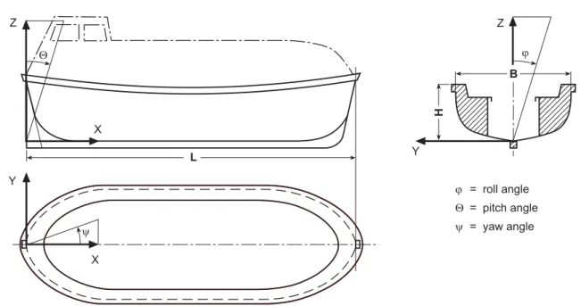
2. Co-ordinate system
For the use of these Rules the fixed, right-handed co-ordinate system 0, x, y, z as defined in Fig. 1.1 is introduced. The origin of the system is situated at the aft end of the length L, at centreline and on the moulded baseline at the boat’s keel. The x-axis points in longitudinal direction of the ship positive forward, the y-axis positive to port and the z-axis positive
upwards. Angular motions are considered positive in a clockwise direction about the three axes.
3. Principal dimensions
3.1 Length L
The length L is the distance between the most for-ward and most aft element of the boat, permanent fender guards excluded, measured parallel to the design waterline.
3.2 Length Lwl
The length at the waterline Lwl is the length measured
at the design waterline parallel to the base line.
3.3 Length LSC
The scantling length LSC is (L + Lwl) / 2.
3.4 Forward perpendicular FP
The forward perpendicular coincides with the moulded side of the plate stem on the waterline on which the length Lwlis measured.
3.5 Breadth B
The breadth B is the maximum moulded breadth of the hull, without permanent fender guard.
3.6 Depth H
The depth H is the vertical distance, at the middle of the length L, from the base line to the top of the gunwale, compare Fig. 1.1.
3.7 Draught T
The draught T is the vertical distance, at the middle of the length L, from base line to design waterline according to the displacement with complete equip-ment and all persons the lifeboat is permitted to ac-commodate on board.
3.8 Draught TMAX
The draught TMAXis the vertical distance between the
lowest point of the immersed hull including append-ages, e.g. rudders, etc. and the design waterline.
4. Frame spacing a
The frame spacing a will be measured from moulding edge to moulding edge of frame.
5. Displacement Δ
The displacement Δ represents the mass of the boat in metric tons at the draught T.
Z X Q X Y L Z j Y H y B j = roll angle Q = pitch angle y = yaw angle
Fig. 1.1 Co-ordinate system and angles of motion
6. Block coefficient CB
Moulded block coefficient at design draught T, based on the length L.
[ ]
3 B moulded displacement volume m atC = ⋅ ⋅ T L B T 7. Boat speeds 7.1 Speed v0
Expected maximum, continuous ahead speed [kn] of the fully loaded boat in calm water, at the draught T, when the total available driving power is acting on the propulsion devices.
7.2 Speed vTow
Expected maximum ahead speed [kn] of the boat in calm water, at the draught T, when the total available driving power is acting on the propulsion devices and the boat is towing a liferaft for 25 persons respec-tively the largest liferaft carried on the ship for which the lifeboat is assigned.
8. Rated driving power
The rated driving power [kW] is defined as continu-ous power to be delivered by the propulsion machin-ery for running at rated speed v0 and with the total available power acting on the propulsion devices.
9. Definition of decks
9.1 Freeboard deck
Freeboard deck is the deck upon which a freeboard calculation is based.
9.2 Weather deck
All free decks and parts of decks exposed to the sea are defined as weather deck.
10. Special definitions for partial and totally
enclosed lifeboats 10.1 Enclosure
Enclosure is a rigid cover of the upper part of the lifeboat which encloses at least 2 x 20 % (partially enclosed fore and aft) or about 100 % (totally en-closed) of the length of the lifeboat.
10.2 Canopy
Canopy is a non-rigid or only partly rigid, mountable and dismountable cover of partially enclosed life-boats between the rigid enclosures at the ends of the lifeboat.
11. Closure conditions
11.1 Watertight
Watertight in relation to a structural element means capable of preventing the passage of water through the structure in either direction with a proper margin of resistance under the pressure due to the maximum head of water which it might have to sustain.
11.2 Weathertight
Weathertight means that in any sea condition water will not penetrate in the lifeboat.
11.3 Weatherproof
Weatherproof means protection from wind, rain and splash water.
12. Angle of heel ϕ
The angle of heel ϕ [°] is measured relative to the x-axis, see Fig. 1.1
13. Special definitions for free-fall lifeboats
13.1 Free-fall certification height HC
The free-fall certification height HC [m] is the great-est launching height for which the lifeboat is to be approved, measured from the still water surface to the lowest point of the lifeboat when the lifeboat is in the launch configuration.(LSA 1.1.4) This height is to be defined in the Certificate of the lifeboat.
13.2 Design free-fall height HD
The design free-fall height HD [m] is the height on
which the design has to be based.
13.3 Launching ramp angle Θ
The launching ramp angle Θ [°] is the angle between the horizontal and the launch rail of the lifeboat in its launching position with the ship on even keel.(LSA 1.1.5)
13.4 Launching ramp length
The launching ramp length is the distance between the stern of the lifeboat and the lower end of the launching ramp. (LSA 1.1.6)
C. Ambient Conditions
1. General operating conditions
1.1 The selection, layout and arrangement of the boat’s structure and all machinery on board shall be such as to ensure faultless continuous operation under defined standard requirements for ambient condi-tions.
1.2 Inclinations and movements of the boat
The assumed limit conditions for inclinations and movement of a lifeboat under the standard require-ments are defined in Table 1.1.
The effects of distortions of the boat’s hull on the machinery installation have to be considered.
1.3 Environment of the boat
The assumed limit conditions for the environment of a lifeboat are contained in Table 1.2.
1.4 Flooded boat
The buoyancy requirements for a damaged boat are defined in Section 3, B.2. The engine shall be capable of operating when the lifeboat is flooded up to the centreline of the crankshaft, see Section 7, B.
1.5 Sunlight
Where exposed to sunlight, the lifeboat shall be resis-tant to deterioration. (LSA 1.2.2.5)
1.6 Corrosion and rotting
Where applicable, the lifeboat shall be rot-proof, corrosion-resistant, and not be unduly affected by seawater, oil or fungal attack.(LSA 1.2.2.4)
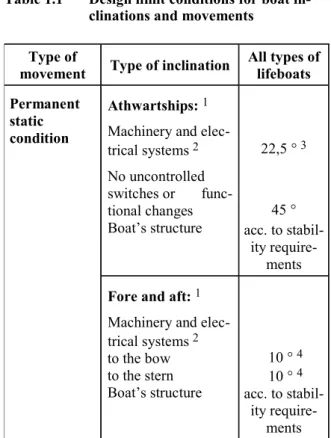
Table 1.1 Design limit conditions for boat
in-clinations and movements Type of
movement Type of inclination All types of lifeboats
Athwartships:1
Machinery and elec-trical systems 2 No uncontrolled switches or func-tional changes Boat’s structure 22,5 ° 3 45 ° acc. to stabil-ity require-ments Permanent static condition
Fore and aft:1
Machinery and elec-trical systems 2 to the bow to the stern Boat’s structure 10 ° 4 10 ° 4 acc. to stabil-ity require-ments
1 athwartships and fore or aft inclinations may
occur simultaneously
2 including electronic equipment
3 for oil tankers, chemical tankers and gas ers angle may be greater than 20 ° for free-fall lifeboats in accordance with the international Convention for the Pollution from Ships 1973 as modified 1978; compare LSA Chapter IV, 4.7.3.2
4 for free-fall lifeboats: inclination angle of ramp
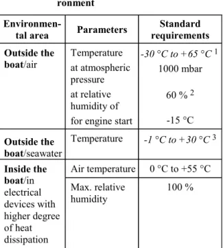
Table 1.2 Design limit conditions for the envi-ronment
Environmen-tal area Parameters requirements Standard
Outside the
boat/air Temperature at atmospheric pressure at relative humidity of for engine start
-30 °C to +65 °C 1 1000 mbar 60 % 2 -15 °C Outside the boat/seawater Temperature -1 °C to +30 °C3 Air temperature 0 °C to +55 °C Inside the boat/in electrical devices with higher degree of heat dissipation Max. relative humidity 100 %
1 not to be damaged in stowage (LSA 1.2.2.2) 2 100 % at a reference temperature of 45 °C for
layout of electrical installations
3 if immersed in seawater during their use, operate throughoutthis seawater temperature
range (LSA 1.2.2.3)
2. Vibrations
Machinery, equipment and hull structures are nor-mally also subjected to vibration stresses. Design, construction and installation shall in every case take account of these stresses and the long-term service of individual components shall not be endangered. For details, like frequency range, limits to be defined, assessment, etc., see GL Rules I – Ship Technology, Part 1 – Seagoing Ships, Chapter 2, Section 1, C.2.
D. Principle Design Requirements
The design of lifeboats and rescue boats has to meet the following principal design requirements.
1. Lifeboats
1.1 General requirements
1.1.1 Construction
All lifeboats shall be properly constructed and shall be of such form and proportions that they have ample stability in a seaway and sufficient freeboard when loaded with their full complement of persons and equipment and are capable of being safely launched under all conditions of trim of up to 10 ° and list of
up to 20 ° either way. All lifeboats shall have rigid hulls and shall be capable of maintaining positive stability when in upright position in calm water and loaded with their full complement of persons and equipment and holed in any one location below the waterline, assuming no loss of buoyancy material and no other damage. (LSA 4.4.1.1)
For details of buoyancy and stability see Section 3.
1.1.2 Carrying capacity
1.1.2.1 No lifeboat shall be approved to
accommo-date more than 150 persons. (LSA 4.4.2.1)
1.1.2.2 The number of persons which a lifeboat to
be launched by falls shall be permitted to accommo-date shall be equal to the lesser of: (LSA 4.4.2.2)
−
the number of persons having an average mass of 75 kg, all wearing lifejackets, that can be seated in a normal position without interfering with the means of propulsion or the operation of any of the lifeboat’s equipment−
the number of spaces that can be provided on the seating arrangements as defined in Section 5, I.1.1.3 Access into lifeboats
1.1.3.1 Every passenger ship lifeboat shall be so
arranged that it can be boarded by its full comple-ment of persons in not more than 10 minutes from the time the instruction to board is given. Rapid disem-barkation shall also be possible. (LSA 4.4.3.1)
1.1.3.2 Every cargo ship lifeboat shall be so
ar-ranged that it can be rapidly boarded by its full com-plement of persons in not more than 3 minutes from the time the instruction to board is given. Rapid dis-embarkation shall also be possible. (LSA 4.4.3.2)
1.1.3.3 The lifeboat shall be so arranged that
help-less people can be brought on board either from the sea or on stretchers. (LSA 4.4.3.4)
1.1.4 Driving power
1.1.4.1 Every lifeboat shall be powered by a
propul-sion system driven by a comprespropul-sion-ignition engine. For details see Section 7, B. (LSA 4.4.6.1)
1.1.4.2 Except for free-fall lifeboats it shall be pos-sible to row the lifeboat to make headway in calm seas. The relevant equipment has to be provided.For details see Section 5, K.(LSA 4.4.8.1)
1.1.5 Speed
The speed of a lifeboat when proceeding ahead in calm water, when loaded with its full complement of persons and equipment and with all engine-powered auxiliary equipment in operation, shall be: (LSA 4.4.6.8)
Sufficient fuel, suitable for use throughout the tem-perature range expected in the area in which the ship operates, shall be provided to run the lifeboat at speed v0 for a period of not less than 24 hours.
1.1.5.2 The towing speed vTow shall be at least 2 kn.
1.1.6 Strength
All lifeboats shall be of sufficient strength to:
1.1.6.1 enable them to be safely launched into the
water when loaded with their full complement of persons and equipment; and (LSA 4.4.1.3.1)
1.1.6.2 be capable of being launched and towed
when the ship is making headway at a speed of 5 kn in calm water. (LSA 4.4.1.3.2)
1.1.6.3 Each lifeboat to be launched by falls shall be
of sufficient strength to withstand the following load, without residual deflection on removal of that load: (LSA 4.4.1.6)
−
in case of boats with metal hulls, 1,25 times the total mass of the lifeboat when loaded with its full complement of persons and equipment, or−
in case of other boats 2,00 times the total mass ofthe lifeboat when loaded with its full complement of persons and equipment.
1.1.6.4 Withstand, when loaded with its full
com-plement of persons and equipment and with, where applicable, skates or fenders in position, a lateral impact against the ship’s side at an impact velocity of at least 3,5 m/s and also a drop into the water from a height of at least 3,0 m. (LSA 4.4.1.7)
1.2 Additional requirements for partially
enclosed lifeboats (LSA 4.5.2)
1.2.1 Partially enclosed lifeboats shall be
pro-vided with permanently attached rigid covers extend-ing over not less than 20 % of L from the stem and not less than 20 % of L from the aftermost part of the lifeboat. The lifeboat shall be fitted with a perma-nently attached foldable canopy which, together with the rigid covers, enclose the occupants in a weather-proof shelter and protects them from exposure and can be easily erected by not more than two persons.
1.2.2 For the arrangement of a radiotelephone
apparatus see Section 8, D.
1.3 Additional requirements for totally
en-closed lifeboats
1.3.1 Every totally enclosed lifeboat shall be
pro-vided with a rigid watertight enclosure which com-pletely encloses the lifeboat. (LSA 4.6.2)
1.3.2 The capacity of lifeboats for ships
navigat-ing under Arctic conditions shall be evaluated with regard to operability, accessibility, seating capacity and overall space considering the needs of personnel
wearing suitable polar clothing. (MSC/Circ. 1056, 11.5.2)
1.3.3 The stability of the lifeboat shall be such that
it is inherently or automatically self-righting when loaded with its full or partial complement of persons and equipment and all entrances and openings are closed watertight and the persons are secured with safety belts. For details see Section 3. (LSA 4.6.3.2)
1.3.4 The lifeboat shall be capable of supporting
its full complement of persons and equipment when the lifeboat is in damaged condition prescribed in 1.1.1 and its stability shall be such that in the event of capsizing, it will be automatically attain a position that will provide an above-water escape for its occu-pants. (LSA 4.6.3.3)
1.3.5 The engine and engine installation shall be
capable of running in any position during capsize and continue to run after the lifeboat returns to the upright or shall automatically stop on capsizing and be easily restarted after the lifeboat returns to the upright. For details see Section 7, B., C. and D. (LSA 4.6.4.2)
1.4 Additional requirements for free-fall
life-boats
1.4.1 Free-fall lifeboats are totally enclosed
life-boats, see 1.3.
1.4.2 Construction
1.4.2.1 Each free-fall lifeboat shall be of sufficient
strength to withstand, when loaded with its full com-plement of persons and equipment, a free-fall launch from a height of at least 1,3 times the free-fall certifi-cation height. (LSA 4.7.4)
1.4.2.2 The required free-fall height shall never
exceed the free-fall certification height. (LSA 4.7.3.3)
1.4.2.3 Each free-fall lifeboat shall be so
con-structed as to ensure that the lifeboat is capable of rendering protection against harmful accelerations resulting from being launched from the height for which it is to be certified in calm water under unfa-vourable conditions of trim of up to 10° and list of up to 20° either way when it is fully equipped and loaded with: (LSA 4.7.5)
−
its full complement of persons−
occupants so as to cause the centre of gravity to be in the most forward position−
occupants so as to cause the centre of gravity to be in the most aft position−
its operating crew only1.4.2.4 For oil tankers, chemical tankers and gas
carriers with a final angle of heel greater than 20 ° calculated in accordance with the International Con-vention for the PreCon-vention of Pollution from Ships, 1973, as modified by the Protocol of 1978 relating
hereto, and the recommendations of the International Maritime Organization (IMO) 1, as applicable, a
lifeboat shall be capable of being free-fall launched at the final angle of heel and on the base of the final waterline of that calculation. (LSA 4.7.3.2)
1.4.2.5 The equipment of the boat , like engine,
tanks, air bottles and spraying system as well as their foundations have also to withstand the decelera-tions/shock loads during the immersion phase, com-pare the relevant Sections where the equipment is defined.
1.4.3 Carrying capacity
The carrying capacity of a free-fall lifeboat is the number of persons that can be provided with a seat without interfering with the means of propulsion or the operation of any of the lifeboat’s equipment.(LSA 4.7.2)The details of the required seats are defined in Section 5, I.2.
1.4.4 Performance
Each free-fall lifeboat shall make positive headway immediately after water entry and shall not come into contact with the ship after a free-fall launching against a trim of up to 10° and a list of up to 20° either way from the certification height when fully equipped and loaded with: (LSA 4.7.3.1)
−
its full complement of persons−
occupants so as to cause the centre of gravity to be in the most forward position−
occupants so as to cause the centre of gravity to be in the most aft position−
its operating crew only1.4.5 For further details see the following
Sec-tions.
1.5 Additional requirements for lifeboats with
self-contained air support system
Lifeboats with self-contained air support system are totally enclosed lifeboats according to 1.3 and, as applicable, may be also free-fall lifeboats according to 1.4.
A lifeboat with a self-contained air support system shall be so arranged that, when proceeding with all entrances and openings closed, the air in the lifeboat remains safe and breathable and the engine runs normally for a period of not less than 10 minutes. During this period the atmospheric pressure inside the lifeboat shall never fall below the outside
atmos-––––––––––––––
1 Reference is made to the damage stability requirements of the International Code for the Construction and Equipment of Ships Carrying Chemicals in Bulk (IBC Code) adopted by the Maritime Safety Committee by resolution MSC.4(48) and the International Code for the Construction and Equipment of Ships Carrying Liquefied Gases in Bulk (IGC Code) adopted by the Maritime Safety Committee by resolution MSC.5(48).
pheric pressure nor shall exceed it more than 20 mbar. The system shall have visual indicators to indicate the pressure of the air supply at all times. (LSA 4.8)
1.6 Additional requirements for
fire-protected lifeboats
1.6.1 A fire-protected lifeboat will normally be a
totally enclosed lifeboat with self-contained air sup-port system, see 1.3. and 1.5.
1.6.2 When waterborne, the lifeboat shall be
ca-pable of protecting the number of persons it is per-mitted to accommodate when subjected to a continu-ous oil fire that envelops the lifeboat for a period of not less than 8 minutes. (LSA 4.9.1)
1.6.3 For details of water spray fire protection
systems see Section 7, D.10.
2. Rescue boats
2.1 Construction
Rescue boats may be either of rigid or inflated con-struction or a combination of both and shall not be less than 3,8 m and not more than 8,5 m in length
(L).(LSA 5.1.1.3.1)
2.2 Carrying capacity
Rescue boats shall be capable of carrying at least five seated persons and a person lying on a stretcher. (LSA 5.1.1.3.2)
2.3 Manoeuvrability
Rescue boats shall have sufficient mobility and ma-noeuvrability in a seaway to enable persons to be retrieved from the water, marshal liferafts and tow the largest liferaft carried on the ship.(LSA 5.1.1.7)
2.4 Driving Power
A rescue boat shall be fitted with an inboard engine or outboard motor. Petrol driven outboard engines with an approved fuel system may be fitted in rescue boats provided the fuel tanks are specially protected against fire and explosion. (LSA 5.1.1.8) For details see Section 7, B.
2.5 Speed
Using its driving power the rescue boat has to reach the following speeds:
2.5.1 Manoeuvring speed v0 of at least 6 kn and
maintaining that speed for a period of at least 4 hours.(LSA 5.1.1.6)
2.5.2 The towing speed vTow shall be at least 2 kn.
(LSA 5.1.1.7)
3. Additional requirements for fast rescue boats
3.1 Length
Fast rescue boats shall have a hull length of not less than 6,0 m and not more than 8,5 m, including in-flated structures or fixed fenders. (LSA 5.1.4.3)
3.2 Speed
Fully equipped rescue boats have to reach the follow-
ing speeds: (LSA 5.1.4.4)
3.2.1 Manoeuvring at a speed of at least 20 kn in
calm water with a crew of 3 persons and maintaining that speed for at least 4 hours.
3.2.2 A speed of at least 8 kn with a full
comple-ment of persons and equipcomple-ment.
Section 2
Certification Procedure
A. General 1. Definition
Certification has to verify compliance with the re-quirements of the GL Rules applicable to a type or a stand-alone unit of lifeboats or rescue boats as well as to their material and components.
The Certification procedure defined in the following may be applied by GL as a notified body according to the Marine Equipment Directive 96/98/EC (MED), as amended of the European Communities or by GL as Classification Society. In the first case a data plate with the mark of conformity according to B.6.1 shall be affixed to the boat. In the second case a mark ac-cording to B.6.2 shall be provided.
2. Request for Certification
A request for Certification shall be lodged by the manufacturer of the boat or his authorized representa-tive to GL.
If GL is requested to act as notified body of the Euro-pean Community the Application Form for Confor-mity Assessment according to the Marine Equipment Directive (MED) 96/98/EC of the European Commu-nities shall be used.
The request shall include:
−
the name and address of the manufacturer and, if the application is lodged by the authorized repre-sentative, his name and address as well−
address of the manufacturer’s production premises−
Quality System Certification by GL or others (if applicable, copy to be attached)−
technical documentation which makes it possible to assess the lifeboat’s/rescue boat’s compliance with the requirements of these Rules; it must cover the design, the building standard, manufacture, in-stallation and functioning of the boat in accor-dance with the technical documentation set down in B.2.−
intended conformity assessment procedure−
copy of other relevant Certifications−
available laboratory/type tests already granted by other authorities−
a written declaration that the same application of the boat or components has not been lodged simul-taneously with any other notified bodyThe applicant shall place at the disposal of GL a specimen of the lifeboat/rescue boat (if not only one unit to be manufactured a boat representative for a series production envisaged and hereinafter called “type”)
3. Certification modules
For application in the European Communities the GL steps of procedure will in their relevant combination satisfy the Module Certification System of the Euro-pean Communities. The correlation of this system to the GL procedures is defined in Table 2.1. If the word-ing is identical with international or European regula-tions it is written in italics.
B. Steps of GL Conformity Procedure
1. Workshop approval
Workshops involved in the manufacturing of lifeboats and rescue boats need GL approval. The requirements to obtain such an approval are defined in the follow-ing.
1.1 General
1.1.1 Requirements to be complied with by the
boatyard and the manufacturers
1.1.1.1 Every manufacturing plant participating in a
lifeboat project is to be provided with suitable equip-ment and facilities to enable proper handling of the materials, manufacturing processes, structural compo-nents, etc. GL reserve the right to inspect the plant accordingly or to restrict the scope of manufacture to the potential available at the plant.
The manufacturing plant has to have at its disposal sufficiently qualified personnel. GL is to be advised of the names and areas of responsibility of all supervi-sory and control personnel. GL reserve the right to require proof of relevant qualification.
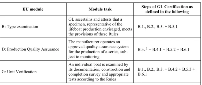
Table 2.1 Correlation of EC modules to GL conformity assessment procedures
EU module Module task Steps of GL Certification as defined in the following
B: Type examination
GL ascertains and attests that a specimen, representative of the lifeboat production envisaged, meets the provisions of these Rules
B.1., B.2., B.3. + B.5.1
D: Production Quality Assurance
The manufacturer operates an approved quality assurance system for the production of a series, sub-ject to monitoring
B.3. 1 + B.4.1 + B.5.2 + B.6.1
G: Unit Verification
An individual boat is examined by its documentation, construction and completion survey and appropriate tests according to the Rules
B.1., B.2., B.3. + B.4.2 + B.5.3 + B.6.1
1 only tests to verify that the quality system is functioning correctly
1.1.1.2 The boatyard or manufacturing plant and its
subcontractors have to get approval from GL for the type of work provided for the manufacture and instal-lation of lifeboats. Approval can only be awarded if the conditions defined in detail in the GL Rules II - Materials and Welding are fulfilled.
1.1.1.3 The fabrication sites, stores and their
opera-tional equipment shall comply also with the require-ments of the relevant Safety Authorities and Profes-sional Associations. The boatyard or manufacturing plant is alone responsible for compliance.
1.1.2 Details in manufacturing documents
1.1.2.1 All significant details concerning quality and
functional ability of the components concerned shall be entered in the manufacturing documents (work-shop drawings, etc.). This includes not only scant-lings but, where relevant, such items as surface con-ditions (e.g. finishing of flame cutting edges and weld seams), and special methods of manufacture involved as well as inspection and acceptance requirements and, where relevant, permissible tolerances.
A production standard which considers the special requirements for the manufacturing of lifeboats has to be defined by the boatyard or manufacturing plant and approved by GL.
1.1.2.2 If, due to missing or insufficient details in
the manufacturing documents, the quality or func-tional ability of the component cannot be guaranteed or is doubtful, GL may require appropriate improve-ments. This includes the provision of supplementary or additional parts (for example reinforcements) even if these were not required at the time of plan approval or if – as a result of insufficient detailing - such re-quirement was not obvious.
1.2 Requirements for metal hulls
1.2.1 Welding
For details of welded joints see GL Rules II - Materi-als and Welding, Part 3 − Welding, Chapter 2 − De-sign, Fabrication and Inspection of Welded Joints, Annex A (Steel) and B (Aluminium).
1.2.2 Cut-outs, plate edges
1.2.2.1 The free edges (cut surfaces) of cut-outs, etc.
are to be properly prepared and are to be free from notches. As a general rule, cutting drag lines, etc. are not be welded out, but are to be smoothly ground. All edges shall be broken or in cases of highly stressed parts, shall be rounded off.
1.2.2.2 Free edges on flame or machine cut plates or
flanges are not to be sharp cornered and are to be finished off as laid down in 1.2.2.1. This also applies to cutting drag lines, etc., in particular to the upper edge of sheer strake and analogously to weld joints, changes in sectional areas or similar discontinuities.
1.2.3 Cold forming
1.2.3.1 For cold forming (bending, flanging,
bead-ing) of plates the minimum average bending radius shall not fall short of 3 times the plate thickness t and shall be at least 2 t. Regarding the welding of cold formed areas, see GL Rules defined in 1.2.1.
1.2.3.2 In order to prevent cracking, flame cutting
flashes or sheering burrs are to be removed before cold forming. After cold forming all structural com-ponents and, in particular, the ends of bends (plate edges) are to be examined for cracks. Except in cases where edge cracks are negligible, all cracked compo-nents are to be rejected. Repair welding is not per-missible.
1.2.4 Assembly, alignment
1.2.4.1 The use of excessive force is to be avoided
during the assembly of individual structural compo-nents or during the erection of sub-assemblies. As far as possible, major distortions of individual structural components shall be corrected before further assem-bly.
1.2.4.2 Girders, beams, stiffeners, frames, etc. that
are interrupted by other structural elements are to be accurately aligned. In case of critical components control drillings are to be made where necessary, which are then to be welded up again on completion.
1.2.4.3 After completion of welding, straightening
and aligning are to be carried out in such a manner that the material properties will not be influenced significantly. In case of doubt, GL may require a procedure test or a working test to be carried out.
1.2.5 Combination of different materials
1.2.5.1 Preventive measures are to be taken to avoid
contact corrosion associated with combination of dissimilar metals with different potentials in an elec-trolyte environment, such as sea water.
1.2.5.2 The selection of different materials has to
take account to the fact that also a combination of metals with composite materials, like fibre reinforced plastics, sandwich constructions, etc. and wood or also of these materials with each other may lead to contact corrosion.
1.2.5.3 In addition to selecting appropriate
materi-als, measures such as suitable insulation or an effec-tive coating can be taken to prevent contact corro-sion.
1.3 Requirements for composite structures
1.3.1 Materials
1.3.1.1 All materials to be used during production of
components from FRP shall first be assessed and approved by GL. Approval by other organizations can be recognized following agreement by GL, pro-vided that the tests required for approval are in ac-cordance with GL requirements.
1.3.1.2 The manufacturer and/or supplier of the
material shall apply to GL-Head Office for approval.
1.3.1.3 Approval is granted if the material fulfils the
requirements of GL. For this purpose, specific tests are necessary, and they shall either be carried out under supervision of GL or the results shall be docu-mented in the report of a recognized testing institute.
1.3.1.4 Before production starts, the required
mate-rial approvals shall be submitted to GL-Head Office and/or the responsible GL inspection office. If no approvals, or not all required approvals have been obtained, then as an exception and following agree-ment with GL-Head Office, proof of the properties of
the basic material can be demonstrated as part of material testing of the component laminate.
1.3.1.5 The packaging or wrapping material shall
bear a reference to the approval.
1.3.2 Manufacturers 1.3.2.1 General
1.3.2.1.1 All manufacturing facilities, store-rooms
and their operational equipment shall fulfil the re-quirements of the responsible safety authorities and professional employer’s liability insurance associa-tions. The manufacturer is exclusively responsible for compliance with these requirements.
1.3.2.1.2 The danger of contamination of laminating
materials shall be minimized through separation of production facilities from store-rooms.
1.3.2.1.3 During laminating and bonding in the
laminating shop, no dust-generating machinery shall be operated nor any painting or spraying operations carried out. As a matter of principle, such work shall take place in separate rooms.
1.3.2.2 Laminating workshops
1.3.2.2.1 Laminating workshops shall be closed
spaces capable of being heated and having supply and exhaust ventilation. During laminating and curing, a room temperature of between 16 °C and 25 °C and a maximum relative humidity of 70 % shall be main-tained, provided that the manufacturer of the laminat-ing resin compound does not specify otherwise.
1.3.2.2.2 In order to control the climatic conditions,
thermographs and hydrographs shall be provided. The equipment shall be set up following agreement with GL, their number and arrangement depending on operational conditions. The equipment shall be cali-brated in accordance with statutory regulations. The recordings shall be kept for at least 10 years and submitted to GL on request.
1.3.2.2.3 Ventilation facilities shall be arranged in
such a manner that no inadmissible amounts of sol-vents are removed from the laminate, and also that no inadmissible workplace concentrations (MAK values) occur.
1.3.2.2.4 The workplaces shall be illuminated
ade-quately and suitably, but at the same time precaution-ary measures shall be taken to ensure that the con-trolled curing of the laminating resin compound is neither impaired through neither sunlight nor lighting equipment.
1.3.2.3 Storage-rooms
1.3.2.3.1 Laminating resins shall be stored in
accor-dance with the manufacturer's instructions. If no such instructions are provided, then they shall be stored in dark, dry rooms at a temperature between 10 °C and
18 °C. The temperature of the storage-rooms shall be recorded continuously by means of thermographs.
1.3.2.3.2 Prepregs shall be stored in special
cold-storage rooms in accordance with the manufacturer's instructions. The temperature in general shall not exceed – 22 °C.
1.3.2.3.3 Hardeners, catalysts and accelerators shall
be stored separately in well-ventilated rooms in ac-cordance with the manufacturer's instructions. If no instructions are provided, they shall be stored in dark, dry rooms at temperatures between 10 °C and 18 °C.
1.3.2.3.4 Reinforcing materials, fillers and additives
shall be stored in closed containers, in dry and dust-free conditions.
1.3.2.3.5 Storage shall be arranged in such a way
that the identification of the materials, their storage conditions and maximum period of storage (expiry date) as prescribed by the manufacturer are clearly visible. Materials whose duration of storage exceeds the expiry date shall be removed immediately from the stores.
1.3.2.3.6 Quantities of materials due to be processed
shall be brought to the production shops as early as possible to ensure complete adjustment to the proc-essing temperature (ΔT = 2 °C), with the containers remaining closed.
1.3.2.3.7 Materials taken from the stores and
par-tially used shall only be replaced in the stores in special cases (e.g. hot-curing prepregs) and with the consent of GL.
1.3.3 Further details
For regulations for processing and other details see GL Rules II – Materials and Welding, Part 2 – Non-metallic Materials, Chapter 1 – Fibre Reinforced Plastics and Adhesive Joints, Section 1.
2. Approval of documentation
2.1 The technical documentation shall in an easily understandable way cover the design, manu-facture and functioning of the boat. It shall enable an assessment of the conformity of the boat with the requirements of these Rules. All data and details shall be given to show in which way the manufacturer guarantees the conformity of the boat to the require-ments.
2.2 The survey of the boat‘s construction will be carried out on the basis of approved documents. All documents have to be submitted to GL in German or English language. Where deemed necessary, calcula-tions and descripcalcula-tions of the boat’s elements are to be submitted. Any non-standard symbols used are to be explained in a key list. All documents have to show the number of the project and the name of the boat-yard.
2.3 The supporting calculations shall contain all necessary information concerning reference docu-ments (parts of the specification, drawings, superior computations, computations for elements or neighbouring elements, following calculations). Lit-erature used for the calculations has to be cited, im-portant but not commonly known sources shall be added as copy.
The choice of computer programs according to the “State of the Art“ is free. It is recommended to use computer programs which are approved by GL in advance as appropriate to solve the actual problems. If the computer programs to be used are not known to GL, they may be checked by GL through compara-tive calculations with predefined test examples. Ref-erence applications, already achieved approvals by other institutions and other relevant information shall be provided in advance. A generally valid approval for a computer program is, however, not given by GL.
The calculations have to be compiled in a way which allows to identify and check all steps of the calcula-tions with regard to input and output in an easy way. Hand-written, easily readable documents are accept-able.
Comprehensive quantities of output data shall be presented in graphic form. A written comment to the main conclusions resulting from the calculations has to be provided.
2.4 The detailed requirements for the documen-tation are defined in Table 2.2.
2.5 GL reserve the right to demand additional documentation if that submitted is insufficient for an assessment of the boat or essential parts thereof. This may especially be the case for plants and equipment related to new developments and/or which are not tested on board to a sufficient extent.
2.6 The drawings are to be submitted in tripli-cate, all calculations and supporting documentation in onecopyfor examination at a sufficiently early date to ensure that they are approved and available to the Surveyor at the beginning of the manufacture or installation of the ship or of important components.
2.7 Once the documents submitted have been approved by GL they are binding on the execution of the work. Subsequent modifications and extensions require the approval of GL before becoming effec-tive.
Table 2.2 List of documents for Certification
Serial number Description
1 2 3 4 5 6 7 8 9 10 11 12 13 14 15 16 17 18 19 20 21 22 23 24 25 26 27 28 29 30 31 32 33 34 35 36 General
List of submitted drawings
General arrangement plan including seating positions Lines plan
General description of the boat type, as far as necessary
Hull Structures
Midboat section and other typical sections Bottom structure including engine foundations Shell expansion plan
Deck, if applicable
Arrangement of buoyant material Bouyancy and flotation calculation Freeboard and stability calculation Details of fixed enclosure, if applicable Tanks
Rudder Seating
Hook arrangement and release mechanism Arrangement of hull outfit
Machinery installations
Details required on GL Forms F 144 and F 144/1 when applying for approval of an internal combustion engine
General arrangement and technical description of the engine Power transmission and propeller
Steering gear
Auxiliary systems and spray system for fire-protected lifeboats, if applicable Ventilation and self-contained air support system, if applicable
Special equipment
Electrical installations
Technical data according to GL Form F 145, as far as applicable
General circuit diagram showing basic systems for power generation, energy storage and distribution
Reports
Design calculations
Reports on fire-retardant or non-combustible hull materials
Test reports/certificates for components already established in unprejudiced way Certificates for equipment installed in the boat
Certificates and reports concerning the manufacturing procedures, inspections, checks, etc. Further documents improving the possibility for Certification by GL
Instructions (for information only)
Installation instructions Operating manual Maintenance manual
Spare parts
2.8 Documents for use on board of the boat
To allow quick action in case of emergency of the lifeboat, the following documentation is to be kept on board of the lifeboat and shall be made available to the GL Surveyor upon request:
−
description of the release system−
description of the motor and propulsion system−
description of the equipment−
survival handbook3. Tests 3.1 Purpose
Testing of the type has to be carried out for:
−
prototypes in the framework of a type approval−
for verification that the quality assurance system is functioning exactly, if necessary−
individual unitsGL will agree with the manufacturer the location where the examinations and necessary tests shall be carried out.
3.2 Specimen
The manufacturer or his authorized representative shall place at the disposal of GL a boat as specimen representative for the production envisaged and here-inafter called “type“. A type may cover several ver-sions of the boat provided that the differences be-tween the versions do not affect the level of safety and other requirements concerning the performance of the boat.
GL may request further specimens if needed for car-rying out the test programme.
3.3 Scope of tests
GL will verify that the type has been manufactured in conformity with the technical documentation.
GL will identify the elements which have been de-signed in accordance with the relevant provisions of the Rules as well as the components which have been designed without applying the relevant provisions of the Rules.
A detail listing of the testing activities is contained in MSC.81(70) of the International Maritime Organiza-tion (IMO) which is included in these Rules in Sec-tion 11. GL will in general follow this list of tests. All tests mentioned above shall be witnessed by a GL Surveyor.
3.4 Test report
A Test Report will be issued by the GL Surveyor. The Test Report Forms according to IMO MSC/Circ.980/Add.1 shall be used.
4. Quality control
4.1 Production quality assurance
4.1.1 Task
The boatyard and the main contractors shall operate an approved quality system for production, final product inspection and testing as specified in 4.1.2 to 4.1.5 and this system shall be subject to surveillance as specified in 4.1.6.(MED D.2) Such a system may be according to the standard ISO 9001:2000 or equivalent.
4.1.2 Application for assessment (MED D.3.1)
The manufacturer shall lodge an application for assessment of his quality system with GL for the products concerned. The application shall include:
−
all relevant information for the envisaged life-boats/rescue boats−
documentation concerning the quality system−
the technical documentation of the approved lifeboat/rescue boat type and a copy of the Type Examination Certificate4.1.3 Elements of the system (MED D.3.2)
The quality system shall ensure compliance of the product with the type as described in the Type Ex-amination Certificate according to 5.1 and with the requirements of these Rules.
4.1.3.1 All the elements, requirements and
provi-sions adopted by the manufacturer shall be docu-mented in a systematic and orderly manner in form of written policies, procedures and instructions. The quality system documentation must permit a consis-tent interpretation of the quality programmes, plan, manuals and records.
4.1.3.2 The quality system shall in particular
in-clude an adequate description of:
−
the quality objectives and the organizational structure, responsibilities and powers of the man-agement with regard to product quality−
the manufacturing, quality control and quality assurance techniques, processes and systematic actions that will be used−
the examinations and tests that will be carried out before, during and after manufacture and the fre-quency with which they will be carried out−
the quality records, such as inspection reports and test data, calibration data, qualification re-ports of the personnel concerned, etc.−
the means of monitoring the achievement of the required product quality and the effective opera-tion of the quality management system4.1.4 Approval audit (MED D.3.3)
4.1.4.1 GL will assess the quality system to deter-mine whether it satisfies the requirements referred to in 4.1.3. For quality management systems that im-plement the harmonized standard ISO 9001:2000 conformity with these requirements will be pre-sumed.
4.1.4.2 The GL auditing team will have at least one
member with experience of assessment in the life-boat/rescue boat technology concerned. The assess-ment procedure will include a visit to the manufac-turer’s premises.
4.1.4.3 The decision of GL will be notified to the
manufacturer. The notification shall include the con-clusions of the examination and the reasoned assess-ment decision.
4.1.5 Modifications (MED D.3.4)
4.1.5.1 The manufacturer shall undertake to fulfil
the obligations arising out of the quality system as approved and to uphold it so that it remains adequate and efficient.
4.1.5.2 The manufacturer or his authorized
repre-sentative established within the European Community shall keep GL (or the notified body that has approved the quality system) informed of any intended updating of that quality system.
4.1.5.3 GL will assess the modifications proposed
and decide whether the modified quality system will still satisfy the requirements referred to in 4.1.3 or whether a reassessment is required.
The manufacturer will be notified of GL’s decision. The notification shall include the conclusions of the examination and the reasoned assessment decision.
4.1.6 Surveillance under responsibility of GL
(MED D.4)
4.1.6.1 The purpose of surveillance carried out by
GL is to make sure that the manufacturer duly fulfils the obligations arising out of the approved quality system.
4.1.6.2 The manufacturer shall allow GL access for
inspection purposes to the locations of manufacture, inspection and testing and storage and shall provide GL with all necessary information, in particular:
−
quality system documentation−
quality records, such as inspection reports and test data, calibration data, qualification reports of the personnel concerned, etc.4.1.6.3 GL will periodically carry out audits to
make sure that the manufacturer maintains and ap-plies the quality system and will provide the manufac-turer with audit reports.
4.1.6.4 In addition GL will make unannounced visits
to the manufacturer. During such visits GL may carry out tests or cause tests to be carried out to check that the quality system is functioning correctly, if neces-sary. GL will provide the manufacturer with a visit report and, if a test has taken place, with a test re-port.
4.1.7 Availability of documents
The manufacturer has to keep, for at least ten years after the last lifeboat/rescue boat has been manufac-tured, at the disposal of the national authorities and GL the following documents: (MED D.5)
−
description of the boat−
technical documentation according to 2.−
documentation of the quality system and any updating of that quality system−
copy of the Type Examination Certificate accord-ing to 5.1−
GL reports and decisions such as approval audit report, reports about periodical audits and unan-nounced visits4.2 Examination of individual units
4.2.1 Task
An individual lifeboat or rescue boat unit shall be tested for its conformity with these Rules. (compara-ble to MED G).
4.2.2 Elements of this step
This step of the procedure contains the following elements:
−
the manufacturer has to ensure that the individual boat or component complies with the require-ments of these Rules and has to declare this to GL−
GL shall examine the individual boat by survey under construction and/or a completion survey and shall carry out appropriate tests according to 3. to ensure that it complies with the relevant re-quirements.5. Certificates
5.1 Type Examination Certificate
5.1.1 Validity
Where the type meets the provisions 1. to 3., GL will issue a Type Examination Certificate to the applicant with a validity of five years. The validity expires immediately if essential modifications are made, see 5.1.3.
If the manufacturer is denied a Type Examination Certificate, GL will provide detailed reasons for such denial, compare 5.1.4.
5.1.2 Content (LSA 4.4.1.2 + 4.7.7)
A Type Examination Certificate shall contain at least the following items:
−
name of certifying organization (GL)−
type and number of the Certificate−
date of issue and validity−
manufacturer’s name and address−
lifeboat type and serial number−
month and year of manufacture−
number of persons the lifeboat is approved to carry−
clearly marked with approval information, in-cluding the institution which approved it (GL )and any operational restrictions defined by GL
(LSA 1.2.2.9)
−
material of hull construction, in such detail as to ensure that compatibility problems in repair should not occur−
total mass fully equipped and fully manned−
the measured towing force of the lifeboat−
statement of approval of the special construction and equipment for the following types of lifeboats, if applicable:−
partially enclosed lifeboats, or−
totally enclosed lifeboats, or−
free-fall lifeboats with−
free-fall certification height−
required launching ramp length−
launching ramp angle for the free-fall certification height−
life boats with self-contained air support sys-tem−
fire-protected lifeboats−
statement of approval of the special construction and equipment for rescue boats, if applicable−
annexed to the Certificate shall be a list of the relevant parts of the technical documentationA copy of the complete documentation will be kept by GL.
5.1.3 Modifications
The manufacturer or his authorized representative shall inform GL of all modifications to the approved boat, which must receive additional approval where such changes may affect compliance with the Rule requirements or the prescribed conditions for use of the boat. (MED B.6)
If approval for such modification is given by GL a new Type Examination Certificate will be issued.
5.1.4 Repeated application (MED B.5)
If a manufacturer is refused a Type Certification, GL will give detailed reasons for that refusal.
Where a manufacturer reapplies for type approval for a lifeboat/rescue boat for which a Type Certifi-cate has been refused, his submission to GL shall include all relevant documentation, including the original test reports, the detailed reasons for the previous refusal and details of all modifications made to the boat.
5.1.5 Exchange of information
5.1.5.1 GL will, on request, provide Flag States
which are members of the European Communities and other notified bodies with the relevant informa-tion concerning the Type Examinainforma-tion Certificates and additions issued and withdrawn. (MED B.7)
5.1.5.2 The other notified bodies may receive copies
of the Certificates and/or their additions from GL. The annexes to the Certificates will be kept by GL at the disposal of other notified bodies. (MED B.8)
5.1.5.3 The manufacturer or his authorized
repre-sentative established within the European Communi-ties shall keep the technical documentation together with copies of the Type Examination Certificates and their additions for at least ten years after the last boat has been manufactured. (MED B.9)
5.2 Certificate of Conformity (Production
Quality Assurance) 5.2.1 Issue
If the manufacturer got already a Type Examination Certificate for a defined boat type and if the provi-sions according to 4.1 are met, GL will issue a Cer-tificate of Conformity (Production Quality Assur-ance) with a validity of five years. The validity ex-pires immediately if essential changes are made, compare 5.2.3.