Threshold displacement energy and damage function in graphite from
molecular dynamics
A.J. McKenna, T. Trevethan, C.D. Latham, P.J. Young, M.I. Heggie
*Department of Chemistry, Faculty of Engineering and Physical Sciences, University of Surrey, Guildford, GU2 7XH, UK
a r t i c l e i n f o
Article history:Received 16 June 2015 Received in revised form 9 November 2015 Accepted 12 November 2015 Available online 22 November 2015
a b s t r a c t
The environment dependent interatomic potential (EDIP) including ZieglereBiersackeLittermark (ZBL)
interactions for close encounters is applied to cascades starting from a host atom and from an interstitial
atom. Wefind the room temperature displacement threshold to be 25 eV, increasing to 30 eV at 900 K.
The latter correlates well with the measured threshold for vacancy production. Additionally, divacancy production is found to occur, including interlayer divacancies from around 60 eV. The data suggest a new, continuous damage function applies, where the threshold region depends on the square root of the primary knock-on atom (PKA) energy in excess of the threshold, evolving to a linear dependence on PKA energy.
©2015 The Authors. Published by Elsevier Ltd. This is an open access article under the CC BY license (http://creativecommons.org/licenses/by/4.0/).
1. Introduction
Graphite is a fundamental core component in present and past gas cooled nuclear reactors in the UK[1]. It may well feature in another generation of reactors (GenIV) operating at high temper-atures, which have been through a number of prototype designs, with the latest being high temperature reactorepebble module (HTR-PM), currently under construction in China.1 Many studies have been made of the effect radiation has on the mechanical and electronic properties of graphite (Kelly 1981[2]).
Radiation damage causes atoms to be displaced from their lat-tice positions to form defects in the crystal structure, either by nuclear collisions or through electronic excitation. Atomic displacement leads to many defects, but the elementary ones are the vacancy, the (self-) interstitial and the bond switch defect. Their ground state structures obtained by Density Functional Theory (DFT) are given inFig. 1(a) to (c), respectively, including their point group symmetries. The interstitial ground state is labelled spiro
[3,4]because it bonds with two pairs of atoms from neighbouring layers, giving a bicyclic carbon backbone, where the cycles share a carbon atom, similar to spiroepentane. The structure confirms in essence, the speculations that the interstitial bonds to host layers in
some way[5,6]. The bond switch or 5775-defect arises from atomic motion similar to the StoneeWales transformation in fullerenes[7], and here we use the term Dienes (D) defect following the Carbon editorial recommendation [8] that recognises earlier work in graphite[9]. The interstitial has a number of metastable structures, for example breaking the pair of bonds to one layer creates the grafted (or bridge) structure[4]. The application of the EDIP po-tential to these defect structures is covered later in Section2.1.
The minimum energy required to displace an atom from its lattice site and form a separated Frenkel pair (FP) is the threshold displacement energy or lattice displacement energy (Ed). Ed is directionally dependent[2], and typically is measured along prin-cipal crystallographic axes or averaged over all directions. A sum-mary of available measurements and theoretical estimates forEdis provided inTable 1.
An early measurement ofEdin graphite was performed by Eggen
[10]with the resultant value of 25 eV recorded in a 1961 paper by Bollmann[11]. The damage was induced by electrons, and defects were detected through changes in electrical resistivity.
In the years that followed, a significant number of investigations of radiation damage in graphite were undertaken. As noted in the reviews of Banhart[12] and Zinkle [13], this resulted in a wide range of values ofEdfrom 10 to 70 eV.
At the lower end of the range of values ofEd, an estimate of 12 eV was extracted from electron-radiation-induced amorphisation of highly ordered pyrolytic graphite (HOPG)[14]. A similarly low value of 10 eV was determined from c-axis oriented electron beam destabilization of graphite to form diamond in an electron *Corresponding author.
E-mail address:[email protected](M.I. Heggie).
1 Irradiation trials of HTR-PM fuel completed,World Nuclear News, January 5, 2015.
Contents lists available atScienceDirect
Carbon
j o u rn a l h o m e p a g e :w w w . e ls e v i e r . c o m / l o c a t e / c a r b o n
http://dx.doi.org/10.1016/j.carbon.2015.11.040
microscope. The latter increased to 20 eV with an isotropic irradi-ation source[15]. As an example of a higher value ofEd, Lucas and Mitchell irradiated natural Ticonderoga graphiteflakes at 15 K with electrons from 0.3 to 2 MeV,finding the onset of resistivity changes between 250 and 350 keV, which corresponded to a value of 60±10 eV forEd[16].
In addition to experimental measurements of Ed, atomistic computer simulations have been employed to determine values of Ed.Ab initiomolecular dynamics (MD) simulations performed by Yazyev et al.[17]found the D defect[7]formed at energies of 30 eV, and intimate FPs were created at 20, 25, and 30 eV. The lowest energy for FP formation was 20 eV from a
b
atom. Interestingly, the resulting interstitial was always in the grafted configuration rather than the ground state spiro [17], within the timescale of the simulation, indicative of a grafted-spiro conversion barrier.Smith and Beardmore investigated sputtering of carbon using classical molecular dynamics (MD) with a Tersoff and Brenner interatomic potential[18]. They reported a value forEdof 34.5 eV for graphite and 34.0 eV for AA-stacked graphite, choosing to compare these with the diamond value of approximately 50 eV
[19]. The 300 K MD simulations of Hehr et al.[20], which employed the REBO potential, and averaged over crystallographic directions,
yielded a value of 44.5 eV. They also demonstrated a weak tem-perature dependence (Eddropping to 42 eV at 1800 K).
It is sensible to look at the threshold displacement energy (TDE) in graphene, the single graphite layer, which has an accurate experimental value of 23.6 eV [21,22]. The absence of confining neighboring layers might be expected to reduce TDE below that of graphite. Krasheninnikov et al. used density functional tight bind-ing MD (DFTB-MD) and arrived at 22 eV[23]. This agrees well with the work of Zobelli[24]who reported a value of 22.2 eV. Using density functional theory, Kelly et al. calculated a value of 23 eV perpendicular to the layer[25]. It is interesting here to note the extreme anisotropy: 23 eV perpendicular to the layer, compared with 780 eV in the direction of a CeC bond in the layer[26]. It seems likely that the latter does not have any tangible effect on experimental values because it only applies to a small solid angle of trajectories at absolute zero.
The IAEA TECDOC 1154[25] appears to endorse an effective value of 40 eV for isotropicfluxes previously proposed by Thrower and Mayer[27], and remarks that the value ofEdused in the UK of 60 eV is‘certainly too high’. Nevertheless, in that same review[27], there is reference to Reynolds' argument[28]that a practical way to account for annealing effects during irradiation and for overlapping Fig. 1.Defect structures from DFT calculations: (a) theC2vvacancy; (b) the spiro-interstitial (C2symmetry) (c) the Dienes (D) defect (C2vsymmetry).
Table 1
The different values for the threshold displacement energy published from experimental results and simulations on irradiated graphite.
Method Ed(eV) Notes
Electron bombardmenta 24.7±0.9 290 K Electron irradiationb 60±10 Electron irradiationc 33±1 (0e60) 60 80 Electron irradiationd 31 Electron irradiatione 24.5 Heþ, Ar, Xeþirradiationf 12
Nobleegas ion irradiation, and CHARMM simulationg 34.5±1
Carbon and ion bombardment, and Tersoff and Brenner MD simulationsh 34.0 AA stacking
34.5 AB stacking
Electron irradiationi 10e20
Literature reviewj 24e60
Carbon knock-on collision, and REBO potential MD simulationk 44.5 300 K
42.0 1800 K
Carbon knock-on collision andab initioMD simulationl 20
a Eggen et al. (1950) Ref.[10]. b Lucas et al. (1963) Ref.[16]. c Montet (1967) Ref.[29]. d Montet (1970) Ref.[30]. e Ohr et al. (1972) Ref.[31].
f Nakai et al. (1991) Ref.[14]. g Marton et al. (1993) Ref.[32]. hSmith et al. (1996) Ref.[18].
i Zaiser et al. (1997) Ref.[15]. j Banhart (1999) Ref.[12]. k Hehr et al. (2007) Ref.[20].
of collision volumes at doses above 1018n cm2(E>1 MeV) is to employ the higher value of 60 eV.
The large variation in reported values ofEdis indicative of the difficulties involved in precisely measuring or calculatingEd. The interpretation of experimental measurements depends on the cri-terion used to define the threshold. Techniques based upon elec-trical or thermal resistance require assumptions about which defects cause the changes. Methods reliant on TEM observations may lack the sensitivity to capture the onset of FP creation.
We thus take the measurement of vacancy concentration as good evidence of FP formation. The technique of etching followed by gold decoration is a proven method and the background con-centration of vacancies in the absence of radiation damage is negligible[33]. Although we note that substitutional boron can give rise to similar etch features, concentrations of boron in nuclear graphites are normally below ~107(Refs.[34,35]).
Our point of reference is then the set of measurements from Montet and coworkers evolving from 33 eV (Ref.[29]) down to 31 eV (Ref.[30]) with the possibility of threshold being at 29.7 eV (Ref.[36]). This work also reveals a possible origin for the report of Ed¼60 eV, being associated with the appearance of concentric etch pits. These arise where two vacancies exist sufficiently close to each other in neighboring layers to bond to each other. In other words they signal formation of interlayer divacancies. The structures and energetics of these defects, labeledV1
2,V22, werefirst discussed by Telling et al.[37]. Given that the etching method employed in the etching experiments involves a 650 C anneal for‘a few minutes’it seems likely that any pair of vacancies from the same displacement group and in neighboring layers can migrate together, form inter-layer divacancies and give rise to these concentric pits.
Dimerization of lattice vacancies from annealing is not consid-ered explicitly in simulations of displacement energies, which are only concerned with the initial displacement (prompt) processes. The behaviour of defects during subsequent annealing is deter-mined by their migration energetics, which are not well described by environment dependent interatomic potential (EDIP)[38], and puts this outside the scope of this article. Nevertheless, we note that such barriers are available fromfirst principles calculations
[39e41].
In this work, we perform molecular dynamics simulations of displacement events in graphite. We present simulations from two energy regimes: 20e100 eV and 0.6e2 keV. Simulations in the low energy range involve sampling from an ensemble of directions of initial velocities. These are used to extract a value ofEdfor graphite, and to examine the defects produced at threshold. A series of higher energy cascades have also been studied to examine the linear regime of the modified Kinchin-Pease (KP) model[42]. Cas-cades in this energy range were reported in a complementary study by Christie et al. [43], which gives images of trajectories, and analysis of timing and spatial extent of cascades at 300 K. The present work validates the method, and establishes the asymptotic behaviour of the low energy cascades, including the new damage function.
2. Method
The simulations reported here are performed using the EDIP MD program package, which implements the EDIP for carbon of Marks et al. [44] splined to the ZieglereBiersackeLittermark (ZBL) po-tential[45] for the screened Coulomb repulsion between nuclei. The EDIP for carbon reproduces the chemical bonding regime arising from the valence electrons, and the ZBL potential re-produces the correct behaviour at small interatomic separations due to high energy collisions. The calculations employ a micro-canonical, or NVE ensemble (meaning number (N) volume (V) and
energy (E) are conserved quantities) and a variable time step. We base our initial analysis on the KP model[42,46]modified with a displacement efficiency,
k
, where E1is the energy of the primary knockeon atom (PKA) when the displacement damage is saturated, i.e. 8e11 keV (Ref.[47]). The number of defectsNdgiven by this model is given by the formulaNd¼ 8 > > > > > > > > > > > < > > > > > > > > > > > : 0 0<E<Ed 1 Ed<E< 2Ed k kE 2Ed 2Ed k <E<E1 kE1 2Ed E1<E<∞ : (1)
Kinchin and Pease took the displacement efficiency to be unity, whereas later Robinson and Torrens[48]using computer simula-tion found
k
¼0.8 independent of energy, temperature and the target material (the method is summarised by Norgett[49]).Edcan be accessed through the location of the threshold in low energy cascades, and through the gradient of the damage function with higher energy cascades. We show later in detail howk
¼0.8 arises from the three generations of knock-on atoms, and we improve the threshold location through extrapolation of a physically justified description of the near threshold damage.2.1. Defect description using the EDIP
A thorough examination of the EDIP applied to defect structures in graphite, using DFT calculations as reference[38], has shown that the radiation defects which form promptly are satisfactorily described and thus it is suitable for estimation of TDE. A summary of EDIP successes against Density Functional Theory/Local Density Approximation (DFT/LDA) calculations follows together with a critical assessment of possible sources of error.
Thefirst DFT calculation of the vacancy revealed it to be dis-torted from Ref.D3hsymmetry toCsin a singlet state by a weak pairwise bonding of two of the three under-coordinated carbon atoms, and a concomitant out-of-plane motion of the remaining such atom[50]. Later it was shown[40,51]that it was closer to a triplet state, possessing a magnetic dipole moment, with a small or zero out-of-plane distortion giving it C2v symmetry for zero distortionFig. 1(a).
The interstitialFig. 1(b) and vacancy both have reasonable for-mation energies:Ef¼5.9 and 6.3 eV against LDA values of 5.9 and 7.9 eV, respectively. The crucially important FP energy is thus 12.2 eV against LDA 13.8 eV, i.e. within 12%, and both are close to the experimental value of 14 eV[27].
The D defect or 5775 defectFig. 1(c) is 5.58 eV versus 5.14 eV for the LDA, and the intimate FP based on a
b
atom[40] is 11.2 eV compared with 10.6 eV for the LDA.Thus, the EDIP performs reasonably well on average for the prompt defects. There are, however,five points to be made about the application of EDIP to radiation damage. Thefirst two concern electronic structure: EDIP is atomistic and makes implicit as-sumptions concerning electrons, i.e. thatithey are always in their ground state so EDIP calculations are always constrained to the Born-Oppenheimer surface, andiithere is no allowance for charge transfer. Thus, the effects of electronic excitation and changes in Fermi level are not included.
Thefinal three points concern minor deviations from the true Born-Oppenheimer energy (hyper-) surface. One such deviation enables
a
carbon atoms in neighboring layers to bond in a meta-stable fashion forming thesp3-sp3link (or‘pinch’defect) (Fig. 2(a))withEf¼2 eV. DFTfinds that thesp3-sp3link defect isnotstable. While the effect of this artefact on stopping power is not known, it is expected to be small, because the energy cost of its formation is only one tenth of the energy of an atomic displacement. A second is the exaggerated penalty for acute bond angles, which prevents closure of the cyclopropyl-like rings of the spiro-interstitial. An open, canted structure (Fig. 2(b)) is formed instead, which fortu-itously, and importantly, has almost exactly the same energy as LDA gives for the spiro-state.
A third deviation gives unusual behaviour for the intimate FP based on an
a
atom. The LDA predicts thatEf¼10.7 eV, and the defect has marginal metastability. For the EDIP, it is unstable, and following structural optimization, it collapses to form asp3-sp3link defect. Such an intimate FP defect has thus not been observed in any of the simulations described here.Finally, investigation of the key diffusion parameters (i.e. migration energies) found them to be a much poorer match with DFT calculated values than formation energies, but no unusually easy paths for transformation are introduced that might distort the results. Although the EDIP barrier to removal of the D defect is very low (0.9 eV compared with DFT 4.5 eV), this is still a high barrier on the time scale of the simulation.
3. Results
Before describing the cascades, wefirst observe that the EDIP threshold for graphene based on a single (001) trajectory is 20.9 eV, which is encouragingly close to the value of 2223 eV given byab initiocalculations[23e25]and 23.6 eV from experiment[21,22]. 3.1. Low energy cascades
Only atomic displacement defects, such as the separated or intimate FP, and the D defect are factored into the assessment of TDE. Where other defects appear, comment is made. We note again that thesp3-sp3link defect (Fig. 2(a)) is not stable infirst principles calculation. The small displacements arising from it have been ignored in measurements of the distance travelled by the PKA.
The resulting displacements are noted in Supplementary Table 1. Generally, the only times that there is a vacancy which is not the original PKA site is when more than one displacement oc-curs. An exception is the (
q
¼90,4¼60) displacement of ana
atom that is along a CeC bond, and displaces the atom neighboring the PKA. The reason this occurs at 60 eV, and not close to Zobelli's 780 eV for graphene, is likely due to thefinite (300 K) temperature used here. Furthermore, the interstitial spiro, (001)-split, or grafted states[37]are all possible for the interstitial; however, only the canted structure shown inFig. 2(b), which has no closed rings of carbon atoms, is generated. At the lower energies, intimate FPs[52]are seen, and on rare occasions D defects form, which appear to have arisen from collapse of an intimate FP, as described in Ref.[52]. Two other unusual cases arise from intimate FP collapse: the
formation of asp3-sp3link and the PKA switching site. Switching site must be through the D transformation in the direct (concerted) exchange diffusion mechanism[9,53].
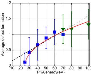
Now we turn to the damage function.Fig. 3plots the number of defects,Nd, as a function of PKA energy,E. The onset of damage is clearly near 25 eV, and by 70 eV single defect production is guar-anteed for every one of our chosen directions. From 60 eV there is evidence of multiple defects. The data suggest an initial square root dependence evolving to linear (matching the high energy data of the next section). The function we have chosen matches the linear regime of equation(1)atE¼2Ed: Nd¼ kffiffiffiffiffi Ed p ! ffiffiffiffiffiffiffiffiffiffiffiffiffiffi EEd p ; (2)
whereEd¼25 eV and
k
¼0.8, for which we provide a justification in the discussion section.The mean distance travelled by the PKA is shown inFig. 4. At 50 eV, it is approximately 0.40±0.18 nm, which is less than half the isotropic average estimated by de Hallas[54]on the basis of his hard sphere scattering model (0.8 nm).
Although our focus has been on average behaviors, and gener-ally there is insufficient precision to break the data down further, we have produced indicative trends based on the energy intervals inSupplementary Table 1. These include the angular dependence of threshold based on the lowest energies at which displacement was observed (Supplementary Figs. 3 and 4). The trends are not far from what the experiments suggest[55], albeit larger, with enhanced threshold for CeC bond directions (
q
¼90, and4¼0and 60). In the same spirit, trends with temperature reveal increasingthreshold with temperature for 300, 600 and 900 K
(Supplementary Fig. 3).
Now we note that divacancies, including interlayer divacancies
[4]appeared above 2Ed, as observed in the experiments of Montet et al.[30]. Their etching technique implies a short anneal occurs at 650 C. At this temperature, according to both theory[40,56,57]and experiment[58], vacancies are expected to be highly mobile, and hence it is anticipated that some FP recombination and dimeriza-tion of vacancies is likely. Extra dimerizadimeriza-tion would similarly elevate the concentration of interlayer divacancies compared with monovacancies. Recombination should be greatest near the
Fig. 2.Defect structures arising from the EDIP that are artefacts of the method, (a) the unstablesp3esp3interlayer link, and (b) the canted interstitial, which represents a substitute for the spiro state.
Fig. 3.Mean defect (FP and D) production (squares and triangles) and standard de-viations as a function ofE. Blue square points are from 1152 atom cells and the green triangles from 33280 atom cells. The (red) curve is the function forNdgiven by equation(2), and the straight (black) dashed line isNd¼kE/2EdwhereEd¼25 eV, and
threshold, where the FP separation is the least, and this is expected to push the threshold to higher energies.
InFig. 5we have taken our data for 900 K and compared them with the experimental results obtained by Montet et al.[30], using linearfits to be compatible with theirs. Given that the conditions are not identical, and the shortcomings of the EDIP in having severely reduced stability of interlayer divacancies, the agreement appears to be quite good.
Finally, we turn to the displacement of interstitial atoms, in an attempt to follow the behaviour of secondary and tertiary knock-on atoms (SKAs and TKAs) which is distinct from that of the PKA. Defect creation requires displacement of a host atomfirmly bound in its lattice site. It occurs more easily when the PKA itself is a host atom, than if the PKA is an interstitial atom which must pass its momentum and energy onto a host atom, because of losses during the atom:atom collision. Moreover, if the interstitial atom is re-trapped by the vacancy created by a displacement, then the net number of atomic displacements is zero.Fig. 6presents the data
that indicates a threshold around 55 eV, much nearer 2Edthan the PKA threshold ofEd.
3.2. High energy
We report two aspects of our simulations, which demonstrate that the slightly different conditions used here closely accords with a parallel study[43]. A typical trajectory is given inFig. 7. Most PKAs create a number of secondaries, and secondaries may create ter-tiaries, but seldom are there further generations of knock-on events which increase the numbers of defects.
Table 2 in supplementarysummarises defect production in the high energy regime, giving average, minimum and maximum values for all ten directions used. In these cases an automated defect search has been performed on the final MD structure following a quench using the steepest descent algorithm. Atoms are considered to be interstitial if they move outside of a cut off radius of 0.1 nm from the nearest lattice site.Fig. 8represents this data, excluding the PKA energy 2 keV, producing a trend line with a gradient 16 keV1, corresponding to Ed ¼ 25 eV with
k
¼ 0.8 equation(1).Fig. 4.Maximum, minimum and weighted average distances travelled by the PKA at 300 K in the orthorhombic 1152- (blue squares) and 33280- (green triangles) atom cells and directions inSupplementary Table 1. The low energy trend line (red) is A ffiffiffiffiffiffiffiffiffiffiffiffiffiffiEEd
p
whereEd¼25 eV, andA¼0.0707 nm eV1/2(A colour version of thisfigure can be viewed online).
Fig. 5.Vacancy (V) (blue) and interlayer divacancy (V2) (red) formation for PKAs at 900 K. Linearfits are given to compare with the linearfits used for the experimental measurement in Ref.[30](shown as dotted lines with arbitrary vertical scaling) (A colour version of thisfigure can be viewed online).
Fig. 6.Defect (FP and D) formation as a function of PKA energy when the PKA is an interstitial atom. Data points correspond to the average and one standard deviation. The red line is an indicative function (fit by eye) equal toBpffiffiffiffiffiffiffiffiffiffiffiffiffiffiffiffiffiffiffiffiffiE55eV, whereB¼0.0516 eV1/2(A colour version of thisfigure can be viewed online).
Fig. 7.Trajectories of principal knock-on atoms for PKA energy of 1000 eV in q¼25,4¼45direction. The paths of the main displacement events are traced by the narrow, branching (light blue) thread. Vacancies are marked by (blue) spheres situated within the graphene sheets of the host. Interstitials inhabit locations between the sheets indicated by (red) spheres (A colour version of thisfigure can be viewed online).
4. Discussion
Ourfirst observation is that our results confirm the conclusions of Christie et al.[43], affirming the binary collision approximation for graphite andfindingEd¼25 eV to be compatible with their data, assuming a modified Kinchin Pease damage function equation(1)
with
k
¼0.8. The focus of this work is on the threshold, and our directionally averaged defect formation suggests a new damage function may apply (Fig. 9):Nd¼ 8 > > > > > > < > > > > > > : 0 0<E<Ed kffiffiffiffiffi Ed p ffiffiffiffiffiffiffiffiffiffiffiffiffiffiEEd p Ed<E<2Ed: k2EE d 2Ed<E (3)
The function is continuous atE¼2Ed, and so is itsfirst differ-ential. The dependence of damage on the square root of energy near the threshold appears to be physically reasonable, since this is a measure of the momentum available to create damage once the threshold is breached.
Next, we consider the physical origin of this function. Scaling the PKA energy by the threshold energy, gives a reduced energyε¼E/ Ed, which simplifies the damage function:
Nd¼ 8 > > > > < > > > > : 0 0<ε<1 kpffiffiffiffiffiffiffiffiffiffiffiε1 1<ε<2: kε 2 2<ε (4)
One anticipates a degree of self-consistency in this function, in that secondaries should be expected to create damage in broadly the same way as the primaries. Thus, the damage should be the sum of the damage from the primaries, secondaries, and tertiaries, with each following a similar damage function. In the interval 1<ε<2 the damage function is only due to the PKA; thus, this function should also be the basis for describing damagef1(ε),f3(ε),f3(ε)etc. from the subsequent knock-on events, suggesting the following: fmðεÞ ¼0 0<ε<m ¼kmpffiffiffiffiffiffiffiffiffiffiffiffiffiεm m<ε ; (5) and Nd¼f1ðεÞð1þf2ðεÞÞð1þf3ðεÞÞ: (6) This would hold provided that the secondaries and tertiaries had the same threshold as the primary. However, we have shown that the threshold is nearer 2 than 1 (Fig. 7). Taking thresholds of 2 for the subsequent knock-on events gives this function:
fmðεÞ ¼0 0<ε<2m1 ¼kmpffiffiffiffiffiffiffiffiffiffiffiffiffiffiffiffiffiffiffiffiffiffiffiffiffiffiffiffiε ð2m1Þ 2m1<ε ; (7) and Nd¼f1ðεÞð1þf2ðεÞÞð1þf3ðεÞÞ: (8) where
k
mare constants reflecting branching ratios (i.e. how many SKAs arise from a PKA) and displacement efficiencies. A plot of such a three stage damage function is given inFig. 10, where the con-stants are chosen to bek
1¼0.73,k
2¼0.19 andk
3¼0.1. Well within the statistical uncertainties of the MD data presented here, it yields Fig. 8.Maximum, minimum, and weighted average number of FP defects as a functionof PKA energy in the high energy regime from Table in supplementary. The solid (red) trend line has a gradient 16 keV1, corresponding toE
d¼25 eV withk¼0.8 equation (1)(A colour version of thisfigure can be viewed online).
Fig. 9.The proposed damage function (equation(3)) (A colour version of thisfigure can be viewed online)).
Fig. 10.The three stage damage function of equations(7) and (8). Thefirst stage is PKA only, the second is PKA plus SKA, and the third this is PKA plus SKA and TKA. The higher energy (linear) regime is shown as a dotted line, and the effective threshold behaviour (equation(4)) matches this line with the PKA line atε¼2 (A colour version of thisfigure can be viewed online).
an effective damage function that looks similar to the one given by equation(4)(Fig. 9), with an effectively linear region showing a displacement efficiency in energy of 0.8, as found long ago in the work of Norgett-Robinson-Torrens [49]. Clearly, there must be limits to the relative sizes of
k
m, since if they were all equal, then the high energy behaviour would be superlinearFig. 10.The displacement efficiencies,
k
2 andk
3 for SKAs and TKAs, respectively, are well below the spherical average of 0.37 implied by the approximatefit inFig. 6, but this could be because the collision processes that give rise to these knock-on events filter out di-rections which are more favourable to defect production.5. Conclusion
This MD simulation has found a room temperature displace-ment threshold to be 25 eV, increasing to 30 eV at 900 K, repro-ducing reasonably well the threshold for vacancy production measured by a direct technique involving temperatures in the re-gion of 900 K[30]. At 60 eV and above divacancies are produced, including interlayer divacancies for which there is direct experi-mental evidence[30]. These are species that bridge the graphite gap[4], inhibit interlayer shear, and potentially buckle the graphite layers[59].
The data suggest a new, continuous damage function (equation
(4)), where the threshold region depends on the square root of the PKA energy in excess of the threshold, evolving to a linear depen-dence on PKA energy. Near the threshold, the constraint on displacement appears to be from momentum considerations, but at higher energies this constraint operates only through the displacement efficiency. The new function can be viewed as being constructed from three individual displacement functions of the same nature from three generations of knock-on events.
A detailed analysis of keV-cascades[43]in graphite has already shown the long predicted absence of thermal spike effects, and the relevance of the binary collision approximation, which are both also confirmed here.
No physically meaningful sub-threshold defects or processes are observed for 20 eV or below; only thesp3esp3link forms, which is an artefact of the interatomic potential used. Nevertheless, some displacements give rise to intimate FPs at the threshold and above. Their collapse could return to any of four states: graphite, D defects, atom interchange, or the unphysicalsp3esp3link.
Acknowledgements
This work was supported by the UK Engineering and Physical Sciences Research Council (grant number EP/I003312/2) and EDF Energy Generation Ltd. AJM thanks Nigel Marks, Marc Robinson and Irene Suarez-Martinez for provision of and training on the EDIP code. We are all also grateful to Prof. Roger Smith (Loughborough University), Dr. Martin Greenhow (Brunel University) and the re-viewers for helpful suggestions. The views expressed in this paper are those of the authors and do not necessarily represent the views of EDF Energy Generation Ltd.
Appendix A. Supplementary data
Supplementary data related to this article can be found athttp:// dx.doi.org/10.1016/j.carbon.2015.11.040.
References
[1] G.B. Neighbour (Ed.), Management of Ageing in Graphite Reactor Cores, Spe-cial Publications, The Royal Society of Chemistry, Cambridge, 2007,http:// dx.doi.org/10.1039/9781847557742.
[2] B.T. Kelly, Physics of Graphite, Applied Science Publishers, Barking and New Jersey, 1981.
[3] M.I. Heggie, B.R. Eggen, C.P. Ewels, P. Leary, S. Ali, G. Jungnickel, R. Jones, P.R. Briddon, LDF calculations of point defects in graphites and fullerenes, in: K.M. Kadish, R.S. Ruoff (Eds.), Fullerenes: Chemistry, Physics, and New Di-rections, Vol. 6 of Recent Advances in the Chemistry and Physics of Fullerenes and Related Materials, The Electrochemical Society, Pennington, NJ, 1998, pp. 60e67.
[4] R.H. Telling, C.P. Ewels, A.A. El-Barbary, M.I. Heggie, Wigner defects bridge the graphite gap, Nat. Mater 2 (5) (2003) 333e337, http://dx.doi.org/10.1038/ nmat876.
[5] L.R. Woolley, Bond energy of vacancies and interstitial atoms in graphite, Nature 4 (1963) 66e67,http://dx.doi.org/10.1038/197066b0.
[6] P.R. Wallace, Configuration of interstitial atoms in irradiated graphite, Solid State Commun. 4 (10) (1966) 521e524, http://dx.doi.org/10.1016/0038-1098(66)90416-9.
[7] A.J. Stone, D.J. Wales, Theoretical studies of icosahedral C60and some related species, Chem. Phys. Lett. 128 (5e6) (1986) 501e503, http://dx.doi.org/ 10.1016/0009-2614(86)80661-3.
[8] M. Monthioux, J.C. Charlier, Giving credit where credit is due: the Stone-(Thrower)-Wales designation revisited, Carbon 75 (2014) 1e4, http:// dx.doi.org/10.1016/j.carbon.2014.03.054.
[9] G.J. Dienes, Mechanism for self-diffusion in graphite, J. Appl. Phys. 23 (11) (1952) 1194e1200,http://dx.doi.org/10.1063/1.1702030.
[10] D.T. Eggen, Energy Required for Atomic Displacements in Graphite Deter-mined by Electron Bombardment, Tech. Rep. NAA-SR-69, North American Aviation, Inc., Los Angeles, Apr. 1950.
[11] W. Bollmann, Electron microscope study of radiation damage in graphite, J. Appl. Phys. 32 (5) (1961) 869e876,http://dx.doi.org/10.1063/1.1736121. [12] F. Banhart, Irradiation effects in carbon nanostructures, Rep. Prog. Phys. 62 (8)
(1999) 1181e1221,http://dx.doi.org/10.1088/0034-4885/62/8/201. [13] S.J. Zinkle, C. Kinoshita, Defect production in ceramics, J. Nucl. Mater 251
(1997) 200e217, http://dx.doi.org/10.1016/S0022-3115(97)00224-9. Pro-ceedings of the International Workshop on Defect Production, Accumulation and Materials Performance in an Irradiation Environment.
[14] K. Nakai, C. Kinoshita, A. Matsunaga, A study of amorphization and micro-structural evolution of graphite under electron or ion irradiation, Ultramicrosc 39 (1991) 361e368,http://dx.doi.org/10.1016/0304-3991(91)90216-S. [15] M. Zaiser, F. Banhart, Radiation-induced transformation of graphite to
dia-mond, Phys. Rev. Lett. 79 (19) (1997) 3680e3683,http://dx.doi.org/10.1103/ PhysRevLett.79.3680.
[16] M.W. Lucas, E.W.J. Mitchell, The threshold curve for the displacement of atoms in graphite: Experiments on the resistivity changes produced in single crystals by fast electron irradiation at 15K, Carbon 1 (3) (1964) 345e352,
http://dx.doi.org/10.1016/0008-6223(64)90290-8.
[17] O.V. Yazyev, I. Tavernelli, U. Rothlisberger, L. Helm, Early stages of radiation damage in graphite and carbon nanostructures: afirst-principles molecular dynamics study, Phys. Rev. B 75 (11) (2007) 115418, http://dx.doi.org/ 10.1103/PhysRevB.75.115418.
[18] R. Smith, K. Beardmore, Molecular dynamics studies of particle impacts with carbon-based materials, Thin Solid Films 272 (2) (1996) 255e270,http:// dx.doi.org/10.1016/0040-6090(95)06052-9.
[19] W. Wu, S. Fahy, Molecular-dynamics study of single-atom radiation damage in diamond, Phys. Rev. B 49 (5) (1994) 3030e3035,http://dx.doi.org/10.1103/ PhysRevB.49.3030.
[20] B.D. Hehr, A.I. Hawari, V.H. Gillette, Molecular dynamics simulations of graphite at high temperatures, Nucl. Technol. 160 (2) (2007) 251e256. [21] J.C. Meyer, F. Eder, S. Kurasch, V. Skakalova, J. Kotakoski, H.J. Park, S. Roth,
A. Chuvilin, S. Eyhusen, G. Benner, A.V. Krasheninnikov, U. Kaiser, Accurate measurement of electron beam induced displacement cross sections for sin-gleelayer graphene, Phys. Rev. Lett. 108 (19) (2012) 196102,http://dx.doi.org/ 10.1103/PhysRevLett.108.196102.
[22] J.C. Meyer, F. Eder, S. Kurasch, V. Skakalova, J. Kotakoski, H.J. Park, S. Roth, A. Chuvilin, S. Eyhusen, G. Benner, A.V. Krasheninnikov, U. Kaiser, Erratum: accurate measurement of electron beam induced displacement cross sections for single-layer graphene, Phys. Rev. Lett. 110 (23) (2013) 239902,http:// dx.doi.org/10.1103/PhysRevLett.110.239902.
[23] A.V. Krasheninnikov, F. Banhart, J.X. Li, A.S. Foster, R.M. Nieminen, Stability of carbon nanotubes under electron irradiation: role of tube diameter and chirality, Phys. Rev. B 72 (12) (2005) 125428, http://dx.doi.org/10.1103/ PhysRevB.72.125428.
[24] A. Zobelli, V. Ivanovskaya, P. Wagner, I. Suarez-Martinez, A. Yaya, C.P. Ewels, A comparative study of density functional and density functional tight binding calculations of defects in graphene, Phys. Status Solidi B 249 (2) (2011) 276e282,http://dx.doi.org/10.1002/pssb.201100630.
[25] B.T. Kelly, B.J. Marsden, K. Hall, D.G. Martin, A. Harper, A. Blanchard, Irradia-tion Damage in Graphite Due to Fast Neutrons in Fission and Fusion Systems, Vol. 1154 of TECDOC, IAEA, Vienna, 2000.
[26] A. Zobelli, A. Gloter, C.P. Ewels, G. Seifert, C. Colliex, Electron knock-on cross section of carbon and boron nitride nanotubes, Phys. Rev. B 75 (24) (2007) 245402,http://dx.doi.org/10.1103/PhysRevB.75.245402.
[27] P.A. Thrower, R.M. Mayer, Point defects and self-diffusion in graphite, Phys. Status Solidi A 47 (1) (1978) 11e37, http://dx.doi.org/10.1002/ pssa.2210470102.
graphite, J. Nucl. Mater 10 (3) (1963) 209e214, http://dx.doi.org/10.1016/ 0022-3115(63)90056-4.
[29] G.L. Montet, Threshold energy for the displacement of atoms in graphite, Carbon 5 (1) (1967) 19e23,http://dx.doi.org/10.1016/0008-6223(67)90101-7. [30] G.L. Montet, G.E. Myers, Threshold energy for the displacement of surface atoms in graphite, Carbon 9 (2) (1971) 179e183,http://dx.doi.org/10.1016/ 0008-6223(71)90129-1.
[31] S.M. Ohr, A. Wolfenden, T.S. Noggle, Electron displacement damage in graphite and aluminum, in: G. Thomas, R.M. Fulrath, R.M. Fisher (Eds.), Electron Microscopy and Structure of Materials, 1971, pp. 964e997. Los Angeles and Berkley.
[32] D. Marton, K.J. Boyd, T. Lytle, J.W. Rabalais, Near-threshold ion-induced defect production in graphite, Phys. Rev. B 48 (10) (1993) 6757e6766, http:// dx.doi.org/10.1103/PhysRevB.48.6757.
[33] G.R. Hennig, Decoration of graphite surfaces for electron microscopy, Appl. Phys. Lett. 4 (3) (1964) 52e55,http://dx.doi.org/10.1063/1.1753959. [34] R.E. Nightingale, Graphite in the nuclear industry, in: R.E. Nightingale (Ed.),
Nuclear Graphite, Academic press, New York and London, 1962, pp. 1e20. Ch. 1.
[35] L.M. Brown, A. Kelly, R.M. Mayer, The influence of boron on the clustering of radiation damage in graphite II. Nucleation of interstitial loops, Philos. Mag. 19 (160) (1969) 721e741,http://dx.doi.org/10.1080/14786436908216330. [36] G.L. Montet, The threshold curve for the displacement of atoms in graphite,
Carbon 11 (2) (1973) 89e92, http://dx.doi.org/10.1016/0008-6223(73)90059-6.
[37] R.H. Telling, M.I. Heggie, Radiation defects in graphite, Philos. Mag. 87 (31) (2007) 4797e4846,http://dx.doi.org/10.1080/14786430701210023. [38] C.D. Latham, A.J. McKenna, T. Trevethan, M.I. Heggie, M.J. Rayson, P.R. Briddon,
On the validity of empirical potentials for simulating radiation damage in graphite: a benchmark, J. Phys. Condens 27 (31) (2015) 316301.
[39] C.D. Latham, M.I. Heggie, J.A. Gamez, I. Suarez-Martínez, C.P. Ewels, P.R. Briddon, The di-interstitial in graphite, J. Phys. Condens. Matter 20 (39) (2008) 395220,http://dx.doi.org/10.1088/0953-8984/20/39/395220. [40] C.D. Latham, M.I. Heggie, M. Alatalo, S.Oberg, P.R. Briddon, The contribution€
made by lattice vacancies to the Wigner effect in radiation-damaged graphite, J. Phys. Condens. Matter 25 (13) (2013) 135403,http://dx.doi.org/10.1088/ 0953-8984/25/13/135403.
[41] T. Trevethan, P. Dyulgerova, C.D. Latham, M.I. Heggie, C.R. Seabourne, A.J. Scott, P.R. Briddon, M.J. Rayson, Extended interplanar linking in graphite formed from vacancy aggregates, Phys. Rev. Lett. 111 (9) (2013) 095501,
http://dx.doi.org/10.1103/PhysRevLett.111.095501.
[42] G.H. Kinchin, R.S. Pease, The displacement of atoms in solids by radiation, Rep. Prog. Phys. 18 (1955) 1e51,http://dx.doi.org/10.1088/0034-4885/18/1/301. [43] H.J. Christie, M. Robinson, D.L. Roach, D.K. Ross, I. Suarez-Martinez, N.A. Marks,
Simulating radiation damage cascades in graphite, Carbon 81 (2015) 105e114,http://dx.doi.org/10.1016/j.carbon.2014.09.031.
[44] N.A. Marks, Generalizing the environment-dependent interaction potential for carbon, Phys. Rev. B 63 (3) (2000) 035401,http://dx.doi.org/10.1103/ PhysRevB.63.035401.
[45] J.P. Biersack, J.F. Ziegler, Refined universal potentials in atomic collisions, Nucl. Instrum. Methods 194 (1e3) (1982) 93e100, http://dx.doi.org/10.1016/0029-554X(82)90496-7.
[46] M.W. Thompson, S.B. Wright, A new damage function for predicting the effect of reactor irradiation on graphite in different neutron spectra, J. Nucl. Mater 16 (2) (1965) 146e154, http://dx.doi.org/10.1016/0022-3115(65) 90046-2.
[47] D. Lexa, M. Dauke, Thermal and structural properties of low-fluence irradiated graphite, J. Nucl. Mater 384 (3) (2009) 236e244,http://dx.doi.org/10.1016/ j.jnucmat.2008.11.013.
[48] M.T. Robinson, I.M. Torrens, Computer simulation of atomic-displacement cascades in solids in the binary-collision approximation, Phys. Rev. B 9 (12) (1974) 5008e5024,http://dx.doi.org/10.1103/PhysRevB.9.5008.
[49] M.J. Norgett, M.T. Robinson, I.M. Torrens, A proposed method of calculating displacement dose rates, Nucl. Eng. Des. 33 (1) (1975) 50e54, http:// dx.doi.org/10.1016/0029-5493(75)90035-7.
[50] A.A. El-Barbary, R.H. Telling, C.P. Ewels, M.I. Heggie, P.R. Briddon, Structure and energetics of the vacancy in graphite, Phys. Rev. B 68 (14) (2003) 144107,
http://dx.doi.org/10.1103/PhysRevB.68.144107.
[51] Y. Ma, P.O. Lehtinen, A.S. Foster, R.M. Nieminen, Magnetic properties of va-cancies in graphene and single-walled carbon nanotubes, New J. Phys. 6 (1) (2004) 68,http://dx.doi.org/10.1088/1367-2630/6/1/068.
[52] C.P. Ewels, R.H. Telling, A.A. El-Barbary, M.I. Heggie, P.R. Briddon, Metastable Frenkel pair defect in graphite: source of Wigner energy? Phys. Rev. Lett. 91 (2) (2003) 025505,http://dx.doi.org/10.1103/PhysRevLett.91.025505. [53] E. Kaxiras, K.C. Pandey, Energetics of defects and diffusion mechanisms in
graphite, Phys. Rev. Lett. 61 (23) (1988) 2693e2696, http://dx.doi.org/ 10.1103/PhysRevLett.61.2693.
[54] D.R. de Hallas, Theory of radiation effects in graphite, in: R.E. Nightingale (Ed.), Nuclear Graphite, Academic press, New York and London, 1962, pp. 195e238. Ch. 7.
[55] T. Iwata, T. Nihira, Atomic displacement in pyrolytic graphite by electron bombardment, Phys. Lett. 23 (11) (1966) 631e632,http://dx.doi.org/10.1016/ 0031-9163(66)90195-8.
[56] G.-D. Lee, C.Z. Wang, E. Yoon, N.-M. Hwang, D.-Y. Kim, K.M. Ho, Diffusion, coalescence, and reconstruction of vacancy defects in graphene layers, Phys. Rev. Lett. 95 (20) (2005) 205501, http://dx.doi.org/10.1103/ PhysRevLett.95.205501.
[57] T. Trevethan, C.D. Latham, M.I. Heggie, P.R. Briddon, M.J. Rayson, Vacancy diffusion and coalescence in graphene directed by defect strainfields, Nano-scale 6 (5) (2014) 2978e2986,http://dx.doi.org/10.1039/C3NR06222H. [58] J.I. Paredes, P. Solís-Fernandez, A. Martínez-Alonso, J.M.D. Tascon, Atomic
vacancy engineering of graphitic surfaces: controlling the generation and harnessing the migration of the single vacancy, J. Phys. Chem. C 113 (23) (2009) 10249e10255,http://dx.doi.org/10.1021/jp901578c.
[59] M.I. Heggie, I. Suarez-Martinez, C. Davidson, G. Haffenden, Buckle, ruck and tuck: A proposed new model for the response of graphite to neutron irradi-ation,, J. Nucl. Mater 413 (3) (2011) 150e155, http://dx.doi.org/10.1016/ j.jnucmat.2011.04.015.