© 2017, IRJET | Impact Factor value: 5.181 | ISO 9001:2008 Certified Journal
| Page 414
STUDY ON INDUCED DRAFT COOLING TOWER PERFORMANCE
ANALYSIS IN CAPTIVE POWER PLANT
UMAKANTA B
1, C.N NATARAJ
21
PG STUDENT, University BDT College of Engineering, Davangere.
2Associate Professor, Department of Studies in Mechanical Engineering,
University BDT College of Engineering, Davangere, Karnataka, India.
---***---Abstract:
Water cooling is generally utilized as a part of numerous mechanical procedures to control warm expulsion from a hot material surface. Keeping in mind the end goal to control the temperature appropriations, a more profound seeing more exact estimation of splash warm exchange rates is required. In another procedure consolidating test and computational displaying produced for water cooling. It is smarter to comprehend the warmth exchange instruments from the ignition gasses to the chilling water and afterward from the cooling water in the earth. To address this issue a rationale tree is produced to give direction on the most proficient method to adjust and distinguish issues inside cooling framework and timetable fitting support. Liquid flow, Thermodynamics and Heat move are included in building up a cooling framework show and the operation is recognizable to the general working organizations. There will be the examination and parametric examination of the cooling framework show in the rationale tree and the outcomes are compressed as tables and diagrams. The goal is to recognize the few methods for enhancing proficiency of cooling tower. In this investigation examination of a few figuring with respect to the cooling tower.KEYWORDS- cooling tower, induced draft, approach, range, cooling capacity, evaporation loss, water flow rate, L/G ratio.
1.
Introduction
Overheating of machine parts is essential issue in industry. It is caused in light of predictable operation of machine and natural conditions of the earth. Operation can't be stopped or by the day's end the machine can't be offered time to be chilled off and thusly there must be course of action for cooling. Water is the best cooling medium as it is trashy and available in wealth. In any case it must be seen that predictable stream of fresh water to the machine is not judicious as it makes unimaginable waste. Cooling towerris use to achieve the inspiration driving freezing with slightest habit of new water. It circles new water for freezing to the apparatus and usages smallest makee up water that is missing in light of dispersal. Beside industry cooled water is required for, for example, ventilation frameworks, or powerrtime. A coolingltower is the apparatus use to reduction the hotness of a waterrstream through expelling high temperature from water and transmitting it to theeair. Coolingltower sort usage of vanishing whereby a little of the water is dispersed into a stirring airrstreamland thusly
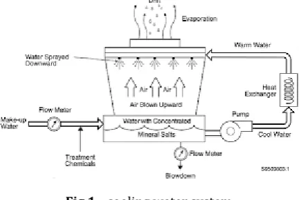
[image:1.595.326.544.312.457.2]settled into theeair. As needs be, whatever remains of the weaken is cooled basically as showed up in the figure. Chilling towers can bring off the water temperature supplementary than devicesl that usage simply airlto scrap warm, like the heater in an auto, and stand along these lines all the more monetarily sagacious and imperativeness profitable.
Fig 1:- cooling water system
2.
Need & what happens in a cooling tower
Evaporation of little piece of cooling tower cools whatever is left of water.
Some measure of sensible warmth trade additionallyhappens.
Cooling water gets soaked with oxygen and differentgasses show in environment.
The current of dry air entering the cooling tower carries with its clean, soil, small scale organic spores, environmental contaminants, and process releases vented to air. The cooling water gets debased.
Concentration of salts in cooling water increments.The salts exhibit in cosmetics water get added to the salts abandoned by the dissipated water.
Process spills sully cooling water.
These changes in cooling water and a portion of the© 2017, IRJET | Impact Factor value: 5.181 | ISO 9001:2008 Certified Journal
| Page 415
3.
Cooling Tower Types
Coolingltowers drop into two main types.
i. Naturalldraft cooling tower.
ii. Mechanicalldraft cooling tower.
3.1
Natural Draft Cooling Tower
Normal draftttowers use wide cement fireplaces to current air over thee media. For the reason that the expansive dimension of theseetowers, they aree for the most part used for waterlstream proportions above 45,000 m3/hr. These sorts of towerslare utilized just by utilitylpowerlstations
3.2
Mechanical Draft Cooling Tower
Mechanical draft towers use extensive fans to drive or draw air through flowed water. The waterfalls descending above seal planes, which support increment the interaction period between the waterland the air- this amplifies warm
exchange between the two. Freezing proportion of
Mechanical draft tower rely on their fan distance across and quickness of process. Subsequently, the mechanical draft cooling tower are considerably further generally utilized, the emphasis is arranged them in this part.
Mechanical draft towers are accessible in the accompanying wind stream courses of action:
A. Counterrflow inducedddraft.
B. Counterrflow forcedddraft.
C. Crosssflow inducedddraft.
a.
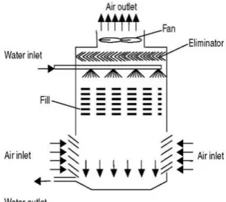
Counter Flow Induced Draft Cooling Tower
[image:2.595.342.537.211.361.2]In the counterrstream prompted draft outline, heated water arrives by the best, whereas the airris presented on the base and departures at the best. Mutually constrained and prompted draft fans are utilized.
Fig 2:-counter flow induced draft cooling tower
b.
Counter Flow Forced Draft Cooling Tower
[image:2.595.322.560.515.658.2]In some constrained draftthostage stream plan, in any case, the water on the base of the seal is directed to a border rack that capacities as the cool water bowl. Propeller followers remain attached underneath the top to pass the appearance over concluded the towerl. Using this outline, the towerris fixed on supports, giving simple entrance near the supporters and their engines.
Fig 3:- forced draft cooling tower
c.
Cross Flow Induced Draft Cooling Tower
In cross stream incited draftttowers, thelwater pass in at the best and ignores the seal. Theeair, in any case, is exhibited along the edge eitherlon one sidel(single-stream tower) or backwards side (twofold stream tower). A prompted drafttfan attractions the air over the moistened seal and ejects it through the most noteworthy purpose of the construction.
[image:2.595.89.253.585.731.2].
Fig 4:- cross flow cooling tower
© 2017, IRJET | Impact Factor value: 5.181 | ISO 9001:2008 Certified Journal
| Page 416
lineall, four-sided, or curved dependent upon theeconditionof the separate cellssand whetherethe air deltas are arranged on the borders or ends of the chambers.
4. Our Cooling Water System
[image:3.595.40.277.186.370.2]In our plant induced draft counter flow cooling tower are using with six cells back to back configuration.
FIG 5:- Structural view of Counter flow induced draft cooling tower
[image:3.595.36.559.312.790.2]Technical details:
Table -1:-induced draft cooling tower details
Cooling tower
Type Induced Draft Counter
Flow
Tower Model 84260-6.0-06B
No. of Cells 06 (back to back
configuration)
No. of towers One (1)
Design Circulating Water
Flow 18000 M
3/hr
I/L (Hot) water temp 42 0C
O/L (Cold) water temp 32 0C
Wet bulb temperature 27 0C
Drift Loss 0.02 %
Evaporation Loss 1.44 %
Circulating water Flow 14166 M3
Total Flow 20166 M3
Each Cell 2361 M3
Cost 2,62,00,000 RS
STRUCTURAL DETAILS
Fans per Cell one
Total Number of Fans Six
Nominal Cell Dimensions L X WX
M 18.39 X 12.90
Overall Tower Dimensions L X WX
M 55.17 X 25.80
Height-Basin Curb to Fan
Deck M 11.66
Overall Tower Height M 15.70
Motor data
No. of Pumps 3 No’s
Pump capacity 8415 m3/hr
Pump speed 590 rpm
Type of pump Vertical mixed flow
Motor Capacity 600 KW
MATERIAL OF CONSTRUCTION
Frame work Members RCC
Casing RCC
Filling PVC Film type
Support RC Beams
RC Beams Support PVC
Louvers, Material None
Fan Deck RCC
Water Distribution –
Type Low pressure non clog spray type
Cold Water Basin –
Material RCC
© 2017, IRJET | Impact Factor value: 5.181 | ISO 9001:2008 Certified Journal
| Page 417
CT FANNumber One per cell
Type Axial Flow propeller type
Manufacturer Paharpur
No. of Blades Eight (8)
Diameter M 10
Fan speed Rpm 98
Tip speed m/sec 51.31
fan, driver output BHP 51.3
Blade Material GRP51.3
Hub Material Fabricated steel HDG
Air Delivery per Fan M3/hr 1491548
5. Components of Cooling Tower
The elementary apparatuses of an evaporativeltower are
1. Frameeand casingg
2. Filll
3. Coldd water basinn
4. Driftt eliminatorss
5. Air inlett
6. Louverss
7. Nozzless
8. Fanss
1. Frameland casingl: Maximum towers havelhelper edges thattassistance the outside isolate ranges (lodgings), engines, followers, and diverse parts. With certain slighter plans, for instance, specific crystal fibre parts, the bundling may fundamentally be the edge.
2. Filll: Maximum towers use seals to empower warm
trade through boosting waterr and airlexchange. Seal can eitherlbe sprinkle or filmlsort.
With sprinkle seal, waterfalls above dynamic
coatings of even sprinkle slabs, industriously contravention into humbler globules, but also moistening the seal superficial. Flexible sprinkle seal propels favoured warmth trade over the wood sprinkle fill.
Film fill contains thin, immovably isolated flexible
planes above which thee water feasts, encircling a tinny filmlin interaction with thelair. These planes
may be level, layered, honeycombedl, or diverse cases. The filmlsort of seal is the supplementary capable and gives similar warmth move in a more diminutive capacity than theesprinkle seal.
3. Coldlwaterlbasin: The freezing waterlbowl, arranged nearby the base of thee tower, gets the chilled waterlthatlstreams off over theltower and seal. The bowl regularly hasla sumplor low pointlfor the frosty waterlexpulsion affiliation. In several tower projects, the icy waterl bowl is underneath the whole seal.
4. Driftteliminatorsl: These catch water beads entangled noticeable all around stream that generally would be lost to the climate
5. Airlinletl: Thislis the reason for entrance for the air inflowing a tower. The cove can takelup a complete sideways of tower-crosslstream plan or be discovered short as a reconsideration or the base of counterlstream diagrams.
6. Louversl: For the most part, cross-stream towerslhave delta louversl. The motivation behind louverssis to adjust wind stream into the seal and hold theewater inside theetower. Several counter stream tower plans don't need louvers.
7. Nozzlesl: These give thelwater showers to wetlthe seal. Constant water dispersion at the highest point of thelseal is basic to accomplish legitimate moistening of thee whole seal superficial. Spouts container eitherlbe settled set up and take eitherl curved or four-sided shower designs or container be a piece of a pivoting get together as initiate in certain roundabout crossl-area towers.
8. Fansl: Bothlcentre point (propellers sort) and spiral followers are used as a piece of towers. Generally, propeller fans are used as a piece of inducedldraftttower and mutually propellerland outward followers are found in compelled draftttowers. Dependent upon their dimension, propellerlfans can eitherr be settled or adjustable pitch.
Fan abstaining non-programmed customizable pitch
sharp edges allows a similar fan to be utilized over an extensive variety of kW with the fan changed in accordance with convey the coveted wind current at the least power utilization.
Automatic variable pitch cutting edges can differ wind
current in light of changing burden conditions.
6. Tower Materials
© 2017, IRJET | Impact Factor value: 5.181 | ISO 9001:2008 Certified Journal
| Page 418
the cool water bowl. On the off chance that the bowlremained not of wood, it probable of cement. Nowadays, towerkmakers create towerskand towerksegments starting an assortment of resources. Regularly a few resources are utilized toward upgrade consumption confrontation, lessen support, and advance unwavering quality and long administration life. Stirred steel, different levels of stainless steel, glass fibre, and cement are generally utilized as a part of tower development and additionally aluminium and different sorts of plastics for a few segments. Wood towers are as yet accessible, however they have glass fibre as opposed to wood boards (packaging) above the timber system. The channel airrlouverssmight be crystal thread, the seal might remain flexible, and the cool water bowl might be strengthen. Bigger tower at times remain finished of cement. Various towerss—housings plus bowls—are built of stirred toughen or, wherever a destructive climate is an issue, stainless-steel. Once in a while an excited towersabstains a stainlessssteel bowl. Crystal thread is additionally broadly utilized for refrigeration towers housings and bowls, providing extended lifetime and insurance after the destructive impacts of numerous substances. Plasticss are generally utilized for seal, counting PVC, polypropylene, and different polymerss. Preserved timber sprinkle seal is as yet determined forr woodd towerss, however elastic sprinkle seal is likewise broadly utilized before water situations command the utilization of sprinkle seal. Film seal, since it suggestions more prominent warmth exchange productivity, remains the seal of decision for requests wherever the coursing water stays for the most part allowed of garbage that might lump the seal ways. Plasticssadditionally catch extensive usage as spout tools. Numerous spouts are existence finished of PVC, ABS, polypropylene, and glass-filleddnylon. Aluminium, glass fibre, and hott-plunged electrifies harden are normally utilized fan resources. Divergent fans are frequently created after aroused steel. Propellerr fans are manufactured from aroused, aluminium, or shaped crystal fibre fortified plasticc
.
7. Cooling Tower Performance
The significant factors, beginning the topic of defining the presentation of coolingl towers, are
Fig 6:-range and approach
1.
“Range” is the contrast among the cooling-tower water gulf and vent temperature. A great CT Choice implies that the cooling-tower has possessed the capacity to lessen the water-temperature successfully, and is subsequently presentation admirably.CT Range (°C) = [CW inlet temp (°C) –CW outlet temp (°C)]
2.
“Approach” is the contrast among thecooling-tower’s outlet icy water temperature and surrounding wet knob temperature. Albeit, together variety and methodology ought to be checked, the Approachfis a superior pointer of cooling-tower’s execution.
CT Approach (°C) = [CW outlet temp (°C) – Wet bulb temp (°C)]
3.
“Cooling tower effectiveness” (in percentagef) is the proportion of variety, to the perfect variety, i.e., contrast among cooling-water delta temperature and surrounding rainy knob temperature.Effectiveness =
4.
“Cooling capacity” is the warmth dismissed in kCal/hr or TR, specified as result of mass stream degree of water, particular warmth and temperatured distinction.5.
“Evaporation loss” is the water amount dissipated for cooling obligation and, hypothetically, for each 10,00,000 kCalswarm banned, vanishing amount workings out to 1.8 m3s. An exact connection utilized regularly isEvaporation Loss (m3/hr) = 0.00085 x 1.8 x circulation rate (m3/hr) x (T
1-T2)
T
1-T2 = Temp. Difference between inlet and outlet water.
6.
“Cycles of concentration” (C.O.C) is the proportion of broke down objects in coursing waterdto the disintegrated objects in cosmetics water.7.
“Blow down” misfortunes rely on series of focus and the dissipation misfortunes and is assumed by connectionBlow Down = Evaporation Loss / (C.O.C. – 1)
© 2017, IRJET | Impact Factor value: 5.181 | ISO 9001:2008 Certified Journal
| Page 419
finest cooling-tower’s adequacy concludedprocedures like water box’s stacking variations, sharp edge point modifications.
Thermodynamics likewise manage that the warmth expelled from the water necessity be equivalent to the warmth consumed by the encompassing air.
L (T1-T2) =G (h2-h1)
=
Wheree
L/G = liquiddto air mass flow relation (kg/kg) T
1 = hot waterr temperaturee(
0 C)
T
2 = icy waterrtemperaturee(
0 C) h
2 = enthalpyrof airrwater vapour mixtureeat
exhausttwet-bulbltemperature. h
1 = enthalpylof air-water vapour mixtureeat
inlett wet-bulbl temperature.
8. Fill Media Effects
In a refrigeration towerl, heated waterlis dispersed over seal medialwhich streams depressed andlis chilled because of vanishing by the mixing air. Airrdraft is accomplished with utilization of fans. In this way certain powerl is expended in drawing the waterlto a stature over theeseal andlfurthermore in fanssmaking theldraftt. A vitality productive or little power devouring cooling-tower is to consume effective outlines of seal medialthrough proper waterldispersion, float eliminatorl, fanl, gearboxl and engine. Powerl reserve funds in the refrigeration towerl, withlutilization of effective seal configuration.
Functionlof Filllmedialin a Coolingl Tower:
Warmth trade amongst air and water is affected through surface range of warmth trade, period of warmth trade (connection) and commotion in water affecting careful quality of merging. Seal medial in the refrigeration towerris dependable to accomplish alllof upstairs.
SplashlFilllMedial: As the description demonstrates, sprinkle seal mediaicreates the mandatory warmth trade zone through sprinkling activity of water above seal media and henceforth contravention into littler water beads. Accordingly, superficial of warmth trade is the shallow range of thelwater beads, whichlis in interaction by air.
FilmlFilll:In a filml seal, water frames a tinny filmlon both adjacent of seal pieces. In this manner territory of warmth trade is the superficial zone of the seal pieces, which is in interaction with air.
9.
Cooling Tower performance analysis
calculation
The findings of one typical trial pertaining to the Cooling Towers of a Thermal Power Plant 1x 100 MW is given below
Observations:
Type of cooling tower = induced draft
Unit load of the station = 100MW
Main frequency = 49.99HZ
Inlet cooling water temperature = 42 oC
Outlet cooling water temperature = 32 oC
Air inlet wet bulb temperature = 27 oC
Air outlet wet bulb temperature = 37 oC
Air inlet dry bulb temperature = 32 oC
Air outlet dry bulb temperature = 40 oC
Number of CT Cells = 6
Dissolved solids in circulating water = 330 ppm
Dissolved solids in makeup water = 40 ppm
Drift losses = 0.02%
Total Measured Cooling Water Flow=14166m3/hr
Measured CT Fan Flow = 1491548 m3/hr
Analysis at 100% Load Generating power plant
Circulating water flow rate = 14166 m3/hr
Range:
CT Range (oC) = [CW inlet temp (oC) – CW outlet temp (oC)]
= [42 – 32] = 10 oC
Approach:
CT Approach = [CW outlet temp (oC) – Wet bulb temp (oC)]
= [32 – 27] = 5 oC
Effectiveness:
© 2017, IRJET | Impact Factor value: 5.181 | ISO 9001:2008 Certified Journal
| Page 420
=
×
100
= 66.667%
Cooling capacity:
Cooling capacity (Q) = mass flow rate of water ×specific heat × temperature difference in kcal/hr
= 14166(m3/hr) ×4.2(kj/kg)×10
= 39.6648 kcal/sec
Evaporation loss:
Evaporation losses in m3/hr = 0.0085 × 1.8× circulation rate(m3/hr) ×(T1-T2)
= 0.0085 × 1.8 × 14166 ×10 = 216.7398 m3/hr
Percentage of evaporation = = 1.53%
Cycles of Concentrations (COC) :
COC =
= COC = 8.25
Blow down losses: Blow down =
=
= 29.895144 m3/hr
Make-up water required:
Total losses in circulating water = Evaporation losses + Blow down losses + Drift losses
= 216.7398 + 29.895144 + 2.8332 = 41.578 m3/hr per cell
Liquid/Gas (L/G) ratio:
L(T1-T2) = G (h3-h1) =
Where:
L/G = liquid to gas mass flow ratio (kg/kg) T1 = hot water temperature (oC)
T2 = cold water temperature (oC)
h3 = enthalpy of air water vapour mixture at exhaust wet-bulb temperature (i.e at 37 oC) from steam table in kcal/kg = ( Cp × T3wb+w3 × hv3wb)
Specific humidity of leaving air w3:
Vapour pressure of the leaving air Pv3
Pv3 = (Pvsat)wb
-Pvsat at 37 oC WBT = 0.06282 bar
= 0.06282
-= 0.06093 bar
Absolute humidity of leaving air w3
w3 = 0.622
= 0.039801 kg/kg of dry air h3 = ( Cp × T3wb+w3 × hv3wb) = (1.005 × 37 + 0.039801 × 2568.14 )
= 33.295 kcal/kg
h1 = enthalpy of air water vapour mixture at inlet wet-bulb temperature (i.e at 27 oC) from steam table in kcal/kg = ( Cp × T1wb+w1 × hv1wb)
Specific humidity of entering air w1:
Vapour pressure of the entering air Pv3
Pv1 = (Pvsat)wb
-Pvsat at 27 oC WBT = 0.0356811 bar
= 0.03505
-=
Absolute humidity of entering air w1
W1 = 0.622
= 0.02 kg/kg of dry air h1 = ( Cp × T1wb+w1 × hv1wb) = (1.005 × 27 + 0.02 × 2549.58 )
= 18.5882 kcal/kg
=
=
= 1.4006
10. CONCLUSION
© 2017, IRJET | Impact Factor value: 5.181 | ISO 9001:2008 Certified Journal
| Page 421
REFERENCES1) M.V.H.Satish Kumar, “Performance Analysis of Cooling
Tower” International Journal of Engineering Trends and Technology (IJETT) – Volume 38 Number 9- August 2016.
2) Krishna S. Vishwakarma1, Arpit S.Bhoyar, Saahil K.
Larokar, Vaibhav V. Hote and Saurabh Bhudhbaware, “Study the factors on which efficiency of cooling tower can be critically acclaimed” International Journal of Engineering Research and Applications ISSN : 2248-9622, Vol. 5, Issue 4, ( Part -3) April 2015.
3) Gaurav Aggarwal, s s Kachhwaha and R S Mishra,
“Parametric study if induced draft counter flow rectangular cooling tower based on exergy analysis” Journal of scientific and Industrial research vol.69, Reccieved 20 May 2009; revised 19 Jan 2010; accepted 27 January 2010.
4) Pooja Rai and Irshad Ahmad Khan, “ Performance
analysis of cooling tower” 4th international conference on recent trends in Engineering science and
management, the international center Goa, 7th August
2016.
5) Xiao Li, Yaoyu Li and John E. Seem, “Dynamic Modeling
of Mechanical Draft Counter-Flow Wet Cooling Tower” International Refrigeration and Air Conditioning Conference 2010.
6) S. Jothibasu. “Energy efficiency improvement in cooling