© 2017, IRJET | Impact Factor value: 5.181 | ISO 9001:2008 Certified Journal | Page 1970
SOLAR BASED ROBOTIC ARM USING MATLAB GUI
K.Yashas Chandra
1, Ch.Dora Babu
2, R.Manikanta
3,O.S.D.Akhilesh
4,E.Rakesh
51,2,3,4,5
Dept. Of EEE, Pragati Engineering College, Surampalem.
---***---Abstract - This project is about designing a robotic arm with two degree of freedom which is controlled by using MATLAB. It is designed to be used in the movement either to the left or right, and also used to lift an object and place it at the desired location with the help of the arm. The locomotion and the control of the arm is achieved by using GUI (Graphical User Interface) in MATLAB. This project also uses Arduino microcontroller circuit as the basic circuit. Two DC Motors will be used as an application extension to make movements and lifting of an object. In this project, microcontroller is programmed instructions to control the Four Channel Relay circuitry which in turn will control the motors.
The objective of this project to develop the Graphical User Interface of device control through MATLAB, interface the MATLAB GUI that consist of transmitter and receiver program with hardware via serial communication and obtain the required control. By using MATLAB GUIDE, the process of laying out and programming GUIs and interface with microcontroller via serial communication port to control the devices will be easier because it is already provided with a set of tools. As a result, the devices at remote location can be controlled by PC having MATLAB GUI and interface the MATLAB GUI with microcontroller via serial communication port
1.INTRODUCTION
Robots are indispensable in many factoring industries. The reason is that the cost per hour to operate a robot is a fraction of the cost per hour to operate a robot is a fraction of the cost human labor needed to perform the same function. More than this, once programmed, robots repeatedly perform function with a high accuracy that surpasses that of the most experienced human operator. Human operators are, however, are more versatile. Humans canswitch job tasks easily. Robots are built and programmed to be job specific.
Robots are in the infantry stage of their evolution. As robots evolve, they will become more versatile, emulating the human capacity and ability to switch job tasks easily. Robots require a combination of elements to be effective sophistication of intelligence, movement, mobility, navigation and purpose
2. Robotic Arm
The simplest arm is the pick-and-place type. In this case the parts are moved from one location to another without caring how the part is picked up or down. However, these days robot arms are designed to manipulate objects having complicated shapes and fragile in nature. These may be used to assemble parts or fit them into clamps and fixture. This is possible due to high accuracy attainable in robot’s arm
3. Main Idea
Our project deals with one of the efficient method to control a robot by using Graphical User Interface (GUI) in MATLAB. This technique is used for easy control of the robot to obtain the pick and place operation. It proposes a cost effective solution to the problem of controlling without other costlier receiving and transmitting equipment using ATmega microcontroller, MATLAB, Four channel relay circuit assembly to ensure robustness, repeatability and easy implementation, the principle idea has been kept very simple. Four channel relay circuit is used to control the operation of the robotic arm and the switching signals provided by the microcontroller through output analog pins to the relays, switching the relay.
BLOCK DIAGRAM:
Fig. 1 Block Diagram
PC with MATLAB is connected to the Arduino through USB port. The communication between MATLAB and Arduino is done through serial communication. The four channel relay circuitry is controlled by programming the micro controller such that certain movement we need is obtained by switching the respective relays. The DC
PC WITH
WINDOWS7
MATLAB
MICRO
CONTROLLER
ATMEGA 328P
4 CHANNEL RELAY CIRCUIT
GRIPPER WITH
DC MOTOR
DEGREE OF
© 2017, IRJET | Impact Factor value: 5.181 | ISO 9001:2008 Certified Journal | Page 1971 Motors are connected to the relay output, and whenever
the relay output is high, the motor starts rotating. The robot having two degree of freedom, the arm consists of one DC Motor and at the gripper it employs another DC Motor. Both of the motors are controlled through four channel relay circuit.
A simple electromagnetic relay consists of a coil of wire wrapped around a soft iron core, an iron yoke which provides a low reluctance path for magnetic flux, a movable iron armature, and one or more sets of contacts .The armature is hinged to the yoke and mechanically linked to one or more sets of moving contacts. It is held in place by a spring so that when the relay is de-energized there is an air gap in the magnetic circuit. In this condition, one of the two sets of contacts in the relay pictured is closed, and the other set is open. Other relays may have more or fewer sets of contacts depending on their function
Relays are simple switches which are operated both electrically and mechanically. We know that most of the high end industrial application devices have relays for their effective working. Relays consist of an electromagnet and also a set of contacts. The switching mechanism is carried out with the help of the electromagnet. The rated current of relay is 7A and 14V DC, for 250V AC the current rating is 7.5A.
A brushed DC motor is an internally commutated electric motor designed to be run from a direct current power source. Brushed motors were the first commercially important application of electric power to driving mechanical energy, and DC distribution systems were used for more than 100 years to operate motors in commercial and industrial buildings. Brushed DC motors can be varied in speed by changing the operating voltage or the strength of the magnetic field.
In the project the movement of the robot is mainly due to the motors with the help of relays. By perfect programming the relays are operated in which the motors rotate to move the robot. In order to get future improvements, each motor is operated by a program. The motors are rated 20mA, 12V DC with a torque of 3kg.
The whole project uses four DC motors in total and six relays, in which four of the relays are connected as four channel relay circuit the whole project is given supply through solar energy power generation
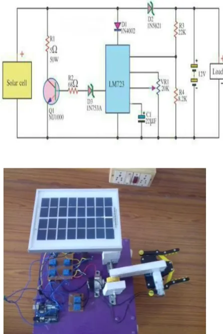
SCHEMATIC DIAGRAM DESCRIPTION:
Power supply being used for the project is generated through solar power generation. power generated from the panel is stored in the battery, a diode circuit is connected between solar panel and battery to prevent the reverse currents flowing from battery to the solar panel. From the battery, supply is given to the Vin of the Arduino board. The voltage regulator in the board regulates the 12v supply to 5v, which can be used by the micro controller.
PC is connected to the Arduino through USB. The programmed is dumped in to the microcontroller through pc and the graphical user interface is loaded into MATLAB. Whenever we press a graphical button in the user interface created in MATLAB GUI, the communication between micro controller and the pc is done through serial communication and according the program we dump, action would take place.
If a graphical button is pressed to move forward, the motor 1 and motor 2 rotate in clock wise direction and the robot moves in forward direction. During this the pin 7 and pin 12 of microcontroller will be high, switching the relay switches and supplying the power to the DC motors making them rotate in the necessary direction.
© 2017, IRJET | Impact Factor value: 5.181 | ISO 9001:2008 Certified Journal | Page 1972 other relays common. When one of the relay switches, the
DC motor starts rotating in one direction and when the other relay switches (and the first one is off) the DC motor starts to rotate in anti-clockwise direction.
Pin 8, pin 9, pin 10, pin 11 are connected to the four inputs of four channel relay circuit. Pin 10 and pin 11 control the arm up and down movements and Pin 8, Pin 9 control the gripper operation. When pin 10 is high and pin 11 is low, the motor 3 rotates in clockwise direction and arm moves upwards and when pin 11 is high and pin 10 is low, the motor 3 rotates in anti-clockwise direction and the arm moves downwards.
When pin 9 is high and pin 8 is low, motor 4 rotates in clock wise direction and the gripper opens when pin 9 is low and pin 8 is high, motor 4 rotates in anti-clockwise direction and the gripper closes.
4.Hardware Equipment
Type In the hardware design the main components used are:
Microcontroller ATMEGA 28 328P. Four channel relay circuit.
Gripper with motor. PV Cell Module.. Charge controller.
a)Microcontroller ATMEGA 28 328P
Microchip Pico Power 8-bit AVR RISC-based microcontroller combines 32KB ISP flash memory with read-while-write capabilities, 1024B EEPROM, 2KB SRAM, 23 general purpose I/O lines, 32 general purpose working registers, three flexible timer/counters with compare modes, internal and external interrupts, serial programmable USART, a byte-oriented 2-wire serial interface, SPI serial port, a 6-channel 10-bit A/D converter (8-channels in TQFP and QFN/MLF packages), programmable watchdog timer with internal oscillator, and five software selectable power saving modes. The device operates between 1.8-5.5 volts. By executing powerful instructions in a single clock cycle, the device achieves throughputs approaching 1 MIPS per MHz, balancing power consumption and processing speed.
b) Four Channel Relay Circuit:
The 4-Channel Relay Driver Module makes it simple and convenient to drive loads such as 12V relays from simple 5V digital outputs of your Arduino compatible board or other microcontroller. When the input from the microcontroller to the base of the Q1 becomes high, the motor1 rotates in clock wise direction. When the input from the microcontroller to the base of the Q2 becomes high, the motor1 rotates in anti-clock wise direction
Fig: Four Channel Relay Circuit
For both the motors to rotate in clockwise direction, both the inputs at the Q1 and Q3 need to be high. For both the motors to rotate in clockwise direction, both the inputs at the Q2 and Q4 need to be high and the inputs at 1 and 2 bases need to be low
c) Gripper with motor:
Specifications of the DC motor that is being used in the Gripper.
Table: Specifications of the DC motor
Voltage 12V
Speed 30 RPM
© 2017, IRJET | Impact Factor value: 5.181 | ISO 9001:2008 Certified Journal | Page 1973 When the motor is given supply such that it to
rotates in Anti- clockwise direction, it rotates the gears through the shaft making the gripper close.
[image:4.595.59.267.174.308.2]d) PV Cell Module:
Fig : structure of a PV module with 36 cells in series
For the majority of applications multiple solar cells need to be connected in series or in parallel to produce enough voltage and power. Individual cells are usually connected in series string of cells (typically 36 or 72) to achieve the desired output voltage. The complete assembly is usually referred to as a module and manufacturers basically sell modules. The modules serve another function of protecting individual cells from water, dust, etc. as the solar cells are placed into an encapsulation of single or double at glasses.
Within a module the different cells are connected electrically in series or in parallel although most modules have a series connection. Figure shows a typical connection of how 36 cells are connected of the individual voltages of each cell. It is therefore, very critical for the cells to be well matched in series string so that all cells operate at the maximum power points. When modules are connected in parallel the current will be the sum of the individual currents and the output voltage will equal that of a single cell.
e) Charge Controller :
A charge controller, charge regulator or battery
regulator limits the rate at which electric current is added to or drawn from electric batteries. It prevents overcharging and may protect against overvoltage, which can reduce battery performance or lifespan, and may pose a safety risk. It may also prevent completely draining ("deep discharging") a battery, or perform controlled discharges, depending on the battery technology, to protect battery life. The terms "charge controller" or "charge regulator" may refer to either a stand-alone device, or to control circuitry integrated within a battery pack, battery-powered device, or battery charger.
A series charge controller or series regulator disables further current flow into batteries when they are full. A shunt charge controller or shunt regulator diverts excess electricity to an auxiliary or “shunt” load, such as an electric water heater, when batteries are full.
4.Results and discussion:
We can operate the robot by using Graphical User Interface(GUI) in MATLAB, required operations can be obtained by pressing the graphical buttons in GUI. By using this we can pick any object and operate the robot in forward, right, left direction and place the object wherever we need
Fig (d) : Overview of project
The Table number 5.1, 5.2 and 5.3 gives the detailed description of the movement of the robot.
Logic 1: It represents the rotation of motor in clockwise direction
Logic 0: It represents the rotation of motor in Anti clockwise direction
[image:4.595.329.552.284.617.2]© 2017, IRJET | Impact Factor value: 5.181 | ISO 9001:2008 Certified Journal | Page 1974 1 is logic 1 and motor 2 is logic 0, the robot moves to left.
When motor 1 is logic 0 and motor 2 is logic 1 the robot moves to right side. When motor logic 0 and motor 2 is logic 1then the robot moves to left. When both motor 1 and motor 2 have the logic 0 then there is no movement in the robot.
The table number fig(d) shows the movement of robot respective to the rotation of the motor1 and motor2
Table 5.1: Movement of Robot according to the rotation of Motors
When motor 3 moves in clockwise direction then the movement of the arm is downward and when the motor 3 moves in anti clock wise direction then the movement of the arm is upward. The below table the arm movements with respect to the rotation of the motor 3
Motor 3 Arm
Movement
Clock wise Downward
Anti-Clock wise Upward
Table5.2: Arm movements according to motors rotation
when the motor 4 moves in clock wise direction then the gripper is open and when the motor 4 move in anti clockwise direction, the gripper closes on to the object. The below table 5.3 shows the operation of
gripper with respect to the rotation of motor 4
Table 5.3: Gripper Operation According to motor rotation
Motor 4 Gripper
Operation
Clock wise Open
Anti-Clock wise Close
6.References:
[5]. P.Manojkumar bookon‘BUILDMATLABGUI’ written in 2003
[6]. Di Santo et al (2004) ‘A distributed architecture for solar energy system based’ power system in California university pages 24-28.
[7]. E. E. Van Dyk and E. L. Meyer, “Analysis of the Effect of Parasitic Resistances on the Performance of Photovoltaic Modules,” Renewable Energy, Vol. 29, No. 3, 2004, pp. 333-344.
[8]. Sang-Hoon Lee, Yan-Fang Li, and Vikram Kapila ‘Development of a Matlab-Based Graphical User Interface Environment for PIC Microcontroller Projects’ in 2004American Society for Engineering Education Annual Conference & Exposition
[9]. Chintan, S.S. and Solanki, C.s., “Experimental evaluation of V-trough PV concentrator system using commercial PV modules”, Solar Energy Materials and Solar cells, vol. 91, p.453, 2007.
[10]. Matt Blackmore, Jacob Furniss, Shaun Ochsner ECE 478/578 Embedded Robotics Fall 2009 Portland State University ‘regarding degree of freedom an end effectors’
[11]. Sunil, K.A., Satyshree, G. and Patil, K.N. Solar Flat Plate Collector Analysis, IOSRJEN. 2012. 2(2) 207-213. [12]. Analysis of Solar PV cell Performance with Changing Irradiance and Temperature Pradhan Arjyadhara1, Ali S.M2, Jena Chitralekha3 International Journal Of Engineering And Computer Science ISSN:2319-7242 Volume 2 Issue 1 Jan 2013 Page No. 214-220
[13]. Atmega328p data sheets
Motor
1 Motor2 Movement of the Robot
1 1 Forward
1 0 Right
0 1 Left
0 0 No
Movement
nc
[1]. Winters, S., Hong, D., Velinsky, S., and Yamazaki, K. (1994). A New Robotics System Co ept for Automating Highway Maintenance Operations.
[2]. Electronics Data Book (1998), http//www.circuitidears.com
[3]. Murray, C.D., and Dermott, S.F. 1999, Solar system dynamics, (New York, Cambridge)