© 2017, IRJET | Impact Factor value: 5.181 | ISO 9001:2008 Certified Journal | Page 1741
Characterization of Casting and Deformation Process of a Metal Alloy
Rahul Srinivasa
1, Ravigoda Patil
11
Department of Electrical and Computer Engineering, University of Rajastan
---***---Abstract -
A measure of alloy’s ability to be cast with a given shape with a given casting process is castability that limited by Fluidity such as surface finish and wall thickness. Good condition of cast products and declines their final quality such as rejection of a shaped casting due to incomplete filling of the mould is influenced by Fluidity. In consequence of the large production volumes included in casting processes decrease in the amount of casting defects can give large economic advantages.Key Words: (Size 10 & Bold) Metal Forming, Castability, Metal thickness
1.
INTRODUCTION
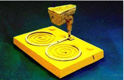
For both pure and commercial aluminium foundry alloys credible fluidity data are not easily attainable. Fluidity has a substantial impact on alloy final quality specially when alloys are part of the systems operating in very high or low temperatures like low temperature refrigeration systems [1]. These systems provide much lower temperatures compared to conventional refrigeration systems [2], as low as -40° C. In any event, for optimization of mould filling calculations during solidification these data are so significant [-1]. In the foundry the distance that a molten metal can flow in a mould of a constant cross-sectional area before it solidifies is denoted by the term “fluidity” . There are various mathematical models that can demonstrate the behaviour of metal while in fluid state as in [3, 4]. This model can useful in determining the effect of aluminium alloys in the harmonics applied to the power systems transmission which may load the customers financially [5]. This explanation is a principle temperature related property of a liquid, thus it is different from the explanation demonstrated in physics which deduces fluidity as the inverse of viscosity [6, 7, 8]. After the first fluidity test in 1902 Fluidity test is accomplished in different ways [9]. For fluidity test different equipment has been developed and modified [10, 11]. The spiral-shaped mould test and the vacuum fluidity test nowadays are the most popular fluidity tests (see Figure 1). The spiral-shaped mould test is by measuring the length that the metal flowed inside a spiral-shaped mould and for vacuum test by using a vacuum pump measures the length the metal flowed inside a narrow channel when sucked from a crucible. Anyway, the spiral test has been widely used because it is compact and transportable thus it can be used easily in the foundry.
Fluidity depends on many factors which can be classified as follows [12]:
Metal variables:
• Chemical composition • Solidification range • Viscosity
• Heat of fusion
Mould and mould/metal variables: • Heat transfer coefficient (coating) • Mould and metal thermal conductivity • Mould and metal mass density • Specific heat
• Surface tension
Test variables:
• Applied metal head • Channel diameter
• Casting temperature (superheat) • Oxide/particle content
Fig -1 Schematic representation of two fluidity tests: a) spiral test; b) vacuum test [13].
[image:1.595.312.542.466.622.2]© 2017, IRJET | Impact Factor value: 5.181 | ISO 9001:2008 Certified Journal | Page 1742 giving a maximum running length of 1.2 m each. Both spiral
[image:2.595.37.290.286.450.2]ends were fully vented. The molten metal was poured manually from the furnace to the pouring basin with a ladle. The temperature of the metal was measured by the operator with a calibrated thermocouple in the ladle, before pouring into the basin. The aim was to pour the molten metal into the basin as fast as possible and to fill up the basin completely, in order to have the same initial metallostatic pressure head on the flowing metal. In a method presented by Gharghabi et al. [14] a new approach was proposed to perform metal forming using electrical shocks. They discuss metal deforming processes that could be applicable in shaping molten metals. This topic is subjected to further research and investigations. For example in [15], the proposed method was utilized to characterize the metal deforming.
Fig -2 Pouring basin and double-spiral mould of the original version of spiral fluidity test equipment
Fluidity can be controlled by selecting the suitable combination of these factors or variables. Misruns happen because of insufficient fluidity of the liquid metal for thin walled castings thus it is a key role [17]. Figure 3 exhibits a misrun in a turbine blade [18]. Misrun takes place when the metal has started solidifying before completely filling the mould.
Fig -3 Misrun in a turbine blade [12].
1.1 Effect of different parameters on fluidity of Al
alloys
Here will exhibit some of the most important results presented in the literature on fluidity as know the fluidity of alloys contingent on many factors. The significance is to suggest an explanation on the influence of fluidity and thus supply a useful database for the modern foundries and cast houses.
1.1.1 Effect of composition
One of the main factors that influence on fluidity is Composition. It understood that fluidity reduce by addition of small alloying to pure metals [19] and for unalloyed aluminium, decreasing purity reduced the fluidity [20]. Fluidity spiral test, Figure 4 exhibits the effect of aluminium purity on fluidity [7]. With 0.4% impurity the fluidity decreased about 25% (Al purity from 100% to 99.6%), and with 0.8% and 1.2% impurity about 37% and 40% reduction (i.e. Al purity of 99.2% and 98.8), respectively [7].
Fig -4 Influence of aluminium purity on fluidity measured by a fluidity spiral test method [7].
Highest fluidity is for Pure metals and eutectic alloys. Exists of impurities significantly reduce the fluidity of pure aluminium but for alloys the fluidity is increased when the fraction eutectic is increased. For a wide range of alloy systems relationship between fluidity and chemical composition has been investigated which have exhibited in reference [7], which may affect the islanding detection in power systems [21].
[image:2.595.313.543.351.500.2]© 2017, IRJET | Impact Factor value: 5.181 | ISO 9001:2008 Certified Journal | Page 1743 Fig -5 Effect of silicon level on fluidity of binary Al-Si alloy [4].
1.1.2 Effect of superheat
The difference between the casting temperature and the liquidus temperature is superheat that it is also a key factor influence of fluidity [22, 23]. With increasing superheat for alloy composition increases the fluidity. Kolsgaard [24] presented that with increasing superheat the fluidity length of Al-7wt%Si-0.6wt%Mg alloy increased linearly. 1ºC increase in melt temperature in the temperature interval 700-760ºC showed that the fluidity length increased 1% [25]. Sahoo and Sivaramakrishnan with a spiral test in sand mould also measured the fluidity of an Al-8.3wt%Fe- 0.8wt%V-0.9wt%Si alloy. They exhibited when the melt temperature increased by 1ºC in the interval 860-900ºC increase of 0.4% in the fluidity length [25]. Kim and Loper measured the effect of pouring temperature on the fluidity of Al-Si and Al-Si-3.5wt%Cu alloys. They investigated five Al-Si alloys, namely 3.6wt%Si, 7.7wt%Si, 11.4wt%Si, Al-13.3wt%Si, Al-16.5wt%Si, and an Al-Si-3.5wt%Cu alloy with four different Si levels. They presented that for all investigated alloys there is a linear relationship between pouring temperature and fluidity. Increasing the pouring temperature increase the melt superheat that causes to delay the nucleation and growth of fine grains, thus the fluidity length increases [26]. For Al-Si hypereutectic alloys, it was understood [27] that with increasing melt superheat up to about 100-150ºC, fluidity increases. This is probably because of increased turbulence in the flowing metal stream [27].
1.1.3 Effect of grain refinement
For effect of grain refinement on fluidity of aluminium alloys a respectable amount of experimental work has been done and the results are slightly contradictory. Mollard et al. [22] exhibited that fluidity reduced in when 0.15 wt% Ti was added to an Al-4.5wt%Cu alloy which tested with a vacuum fluidity apparatus. Tiryakioglu et al. [19] understood with adding 0.04 wt% Ti as Al- 5wt%Ti-1wt%B master alloy there isn’t any effect of grain refinement on the fluidity of an A356 alloy that tested in a sand spiral test. Lang [22] found a consequential increase in fluidity with adding boron in the
range of 0.04-0.07wt% B to Al-Si alloys which tested with a bar die casting. Dahle et al. [28, 29] showed a more complex variation of fluidity with continuous adding of Al-5wt%Ti-1wt%B in Al-7wt%Si-Mg and Al-11wt%Si-Mg alloys. With grain refinement below 0.12wt% Ti reduced the Fluidity and for above 0.12wt% Ti increased the fluidity. With 0.01wt% Ti the fluidity length decreased 5% and for up to 9% further addition of 0.12wt% Ti is needed [29].
1.1.4 Effect of modification
One of a common industrial practice is the modification of Al-Si alloys. With adding the modifiers such as Sr and Na to Al-Si alloys change the eutectic structure from a lamellar to a fibrous morphology and improve the ductility of the alloys. The drawback of modification practice increases porosity that it has been exhibited [30]. Porosity as weak zones reduces the strength of materials and structures [31, 32]. Data that presented [24, 33] exhibit fluidity slightly decreased with adding modifiers. Kotte [34] understood that fluidity reduced with both Sr and Na but slightly more significant reduction in fluidity caused with adding Na. Venkateswaran et al. investigated [35] the effect of different modifiers on the fluidity of eutectic Al-Si alloys. With adding of Na, Na plus Sr, Ti, Na decrease fluidity [36].
1.1.5 Effect of mould material, grain size, moisture
content and binder
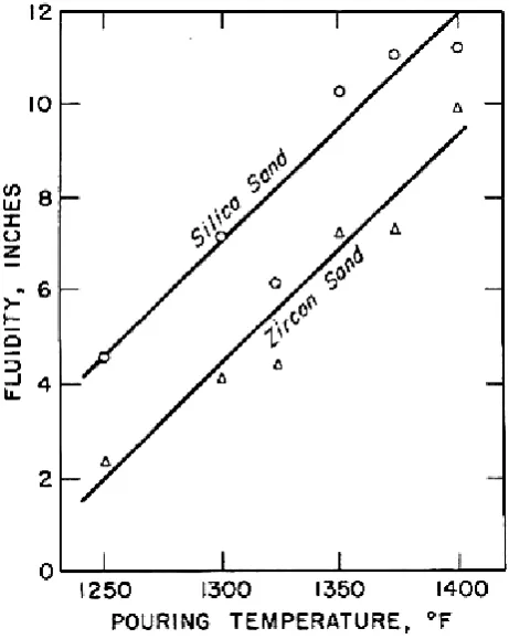
The effect of mould material has also been investigated [36, 37]. Flemings et al. [36] exhibited the influence of mould materials (green-, core-, CO2- and zircon sand) on the fluidity of an Al-4.5wt%Cu alloy. They understood that fluidity influenced with the mould material. For example, fluidity in core sand was 20 to 27% lower than in green sand; and in zircon sand 22 to 55% lower than in green sand. In Figure 6, the effect of silica sand and zircon sand moulds on fluidity showed. Because of the greater thermal diffusivity of zircon sand fluidity of castings in silica sand was higher than in zircon sand [36].
2 EFFECT OF MOULD COATING
[image:3.595.42.276.104.248.2]© 2017, IRJET | Impact Factor value: 5.181 | ISO 9001:2008 Certified Journal | Page 1744 Fig -6 Fluidity of Al-4.5wt%Cu alloy versus pouring
temperature when poured in silica and zircon sand (both sands were bentonite bonded, green and 110 AFS)
transfer coefficient by less than a factor of four resulted in 200% increase in fluidity. Vacuum fluidity test method present that Doubling HTC caused 40% decrease in fluidity [36].
2.1 Effect of pressure head, melt cleanliness and
viscosity
Pressure head which forces the liquid metal through the “pipe” that forms during solidification in a narrow channel affected on fluidity. Thus, the taller the sprue has greater fluidity. However, Tiryakioglu et al. [13] exhibited that small variations of metallostatic pressure do not meaningfully effect on fluidity. It presented that for increase the fluidity increasing the sprue height would not be a perfect choice. So, for adversely affect fluidity, small variations in the pressure are not assumed [13]. Groteke [37] exhibited for fluidity a significant effect of the melt cleanliness. By purging with inert and halogen gases cleaned 319 alloys and Almag observed Up to 20% improvement in fluidity. However, for removing inclusions from the melt when halogen gases or mixtures were used, the use of inert gas alone was no impressive [7]. The viscosity of molten metals is completely low, for instance under 0.003 Pa for Al-7wt%Si-Mg alloy [37]. To give a report for observed variation in fluidity, changes in viscosity with temperature and/or slight changes in composition are not enough. Also Jones et al. [38] by a spiral test showed that the fluidity of a molten metal does
not depend on viscosity. Hence, the effects of viscosity can be neglected as well as surface tension on fluidity in a casting mould [23, 39].
The manufactured part/structure should be under regular inspection to detect defects due to the manufacturing process or service life. Wave propagation is one of the most common methods [40, 41]. Laser Engineered Net Shaping (LENS®) is a Direct Laser Deposition (DLD) additive manufacturing technology that can be used for directly building complex 3D components from metal powders in a combined deposition/laser-melting process [42]. Bagheri et al,. [42] investigated the effect of LENS process parameters, such as laser power, powder feed rate and traverse speed, on the resultant microstructure, hardness and tensile strength of Ti-6Al-4V components is experimentally investigated. Farhatnia et al,. [43-44] studied buckling analysis of functionally graded (FG) thick beam under different conditions is presented. Based on the first order shear deformation theory, governing equations are obtained for Thimoshenko beam which is subjected to mechanical loads. In functionally graded materials (FGMs) [45] the material properties obeying a simple power law is assumed to vary through thickness. However, in some case it can vary without any visible changes [46]. In order to solve the buckling differential equations, Generalized Differential Quadrature Method (GDQM) is employed and thus a set of eigenvalue equations resulted. For solving this eigenvalue problem, a computer program was developed in a way that the influence of different parameters such as height to length ratio, various volume fraction functions and boundary conditions were included. Non-dimensional critical stress was calculated for simply-simply, clamped-simply and clamped-clamped supported beams [47, 48]. The results of GDQ method were compared with reported results from solving the Finite element too. The comparison showed the accuracy of obtained results clearly in this work.
2.2 CONCLUSION
The following conclusions can be drawn from this study: For fluidity, chemistry of aluminium alloy has a significant role and the Si content has a serious significance. However, small variations in minor alloying elements do not significantly effect on fluidity.
Casting temperature and melt superheat plays an important role for fluidity. The role of alloy chemistry and mould coating at high melt superheats is decreased. Adding Grain refiner to a previously refined Al-Si alloy
do not significantly effect on fluidity.
Dissolved hydrogen does not effect on fluidity. However, as anticipated, porosity increased with high hydrogen content.
[image:4.595.44.275.105.395.2]© 2017, IRJET | Impact Factor value: 5.181 | ISO 9001:2008 Certified Journal | Page 1745 their thickness in addition to the mould roughness will
also effect on fluidity.
Commercial casting simulation software used for predicting fluidity so it is very important.
REFERENCES
[1] Aghniaey, Sama, and SEYED MOHAMMAD SEYED MAHMOUDI. "Exergy analysis of a novel absorption refrigeration cycle with expander and compressor." Indian Journal of Scientific Research (2014).
[2] Aghniaey, Sama, S. Mohammad S. Mahmoudi, and Vahid Khalilzad-Sharghi. "A comparison between the novel absorption refrigeration cycle and the conventional ammonia-water absorption refrigeration cycle." International Conference on Heat Transfer, Fluid Mechanics and Thermodynamics, 2014.
[3] F. Abbasi, and J. Mohammadpour "Nonlinear model order reduction of Burgers' equation using proper orthogonal decomposition," Proceedings of American Control Conference (ACC), Chicago, 2015.
[4] F. Abbasi and J. Mohammadpour "Reduced order model-based sliding mode control of dynamic systems governed by Burgers' equation." IEEE 54th Annual Conference on Decision and Control (CDC), Osaka, 2015.
[5] H. Norouzi, S. Abedi, R. Jamalzadeh, M. Ghiasi Rad, and S. H. Hosseinian "Modeling and investigation of harmonic losses in optimal power flow and power system locational marginal pricing" Energy, 68 (2014), pp. 140– 147.
[6] F., Batllo, “Method of improving the removal of investment casting shells”. U.S. Patent Application (2003), No. 10/337,799.
[7] F., Batllo, Viers, D.S., Mosher, J.S, “Method of improving the removal of investment casting shells”. US Patent No. 0081350 Al (April 20). [6] M. C. Flemings, Solidification Processing, McGraw-Hill Inc., London, 1974.
[8] M. Bakhtiary-Noodeh, S. Moradian, and Z. Ranjbar, “Improvement of the edge protection of an automotive electrocoating in presence of a prepared epoxy-amine microgel” Progress in Organic Coating, 103 (2017), pp. 111–125.
[9] P.R. Beeley, R.F. “Smart Investment Casting (first ed.)” The Institute of Materials, London (1995) pp. 68–71. [10] H. Bleier, C. Kukla “Quality in the production of wax
patterns” Foundry Trade Journal, 25 (2) (2002), pp. 20– 22.
[11] A. Borcherding, T. Luck “Application of plant proteins as thermoplastics” Plant Proteins Europe Crops (2000), pp. 313–318.
[12] J.B.F. Brum “Microwave dewaxing applied to the investment casting process” Journal of Materials Processing Technology, 209 (2009), pp. 3166–3171. [13] R.T., Carter “Method of casting refractory shells”. Patent
No. 2968848 (January 24 1961).
[14] P. Gharghabi, P. Dordizadeh B., and K. Niayesh, “Impact of Metal Thickness and Field-Shaper on the Time-Variant Processes during Impulse Electromagnetic Forming in Tubular Geometries,” Journal of the Korean Physical Society, vol. 59, no. 61, 2011, p. 3560-3566, doi.org/10.3938/jkps.59.3560
[15] P. Dordizadeh-Basirabad, P. Gharghabi, and K. Niayesh, “Dynamic Analysis of a Fast-acting Circuit Breaker (Thompson) Drive Mechanism,” Journal of the Korean Physical Society, vol. 59, pp. 3547-3554, 2011, doi.org/10.3938/jkps.59.3547.
[16] Shanthala, K., and T. N. Sreenivasa. "Stress Analysis of Field Shaper in ElectroMagnetic Welding." International Journal of Scientific Research 4, no. 5 (2016).
[17] H. Chattopadhyay “Estimation of solidification time in investment casting process” International Journal of Advanced Manufacturing Technology 2010.
[18] C.M. Cheah, C.K. Chua, C.W. Lee, C. Feng, K. Totong “Rapid prototyping and tooling techniques: a review of applications for rapid investment casting” International Journal of Advanced Manufacturing Technology, 25 (2005), pp. 308–320.
[19] A.J. Clegg “Precision Casting Processes” Pergamon Press, Oxford (1991).
[20] R.G. Craig, J.D. Eick, F.A. Peyton “Properties of natural waxes used in dentistry” Journal of Dental Research, 44 (6) (1965), pp. 1308–1316.
[21] H. Jouybari-Moghaddam, S. H. Hosseinian, B. Vahidi, and M. Ghiasi Rad "Smart control mode selection for proper operation of synchronous distributed generators" Smart Grids (ICSG), 2012 2nd Iranian Conference on. IEEE, (2012).
[22] M. Masoomi, S. M. Thompson, N. Shamsaei, A. Elwany, and L. Bian, “An experimental-numerical investigation of heat transfer during selective laser melting,” in 26th International Solid Freeform Fabrication Symposium, 2015.
[23] M. Masoomi, N. Shamsaei, X. Gao, S. M. Thompson, A. Elwany, L. Bian, N. Shamsaei, L. Bian, and A. Elwany, “Modeling, simulation and experimental validation of heat transfer during selective laser melting,” in ASME 2015 International Mechanical Engineering Congress & Exposition, 2015.
[24] R.S., Doles, D.S., Viers, “Filler component for investment casting slurries”. US Patent No. 7588633 B2, 2009. [25] W.P. Eddy, R.J. Barbero, W.I. Dieters, B.J. Esarey, L. Frey,
J.R. Gros T. Lyman (Ed.) “Investment Casting, American Society for Metals” Ohio (1974), pp. 237–261.
[26] G.H., Foster “Method and apparatus for removing wax from casting mould”. US Patent No. 5372177, 1994. [27] Y.B. Gil, A.J. Hernandez, A.P. Unzueta, E.G. Sanchez, R.M.
Solis, M.A.L.H. Rodriguez “Influence of heat treatments on mechanical properties of a biocompatibility alloy” ASTM F75, Mexican Journal of Physics, 55 (1) (2009), pp. 1–5.
[28] J. Guan, G.W. Dieckhues, P.R. Sahm “Analysis of residual stresses and cracking of γ-TiAl castings” Intermetallics, 2 (1994), pp. 89–94.
[29] A. Yaghoobi, M.G. Chorzepa, S.S. Kim, S.A. Durham "Mesoscale Fracture Analysis of Multiphase Cementitious Composites Using Peridynamics." Materials 10, no. 2 (2017), pp. 162.
[30] A. Yaghoobi, M.G. Chorzepa "Fracture analysis of fiber reinforced concrete structures in the micropolar peridynamic analysis framework." Engineering Fracture Mechanics 169 (2017), pp. 238-250.
© 2017, IRJET | Impact Factor value: 5.181 | ISO 9001:2008 Certified Journal | Page 1746 investment cast aluminum alloys” Materials Science and
Engineering A, 343 (2003), pp. 290–300.
[32] R.A., Horton “Method of casting a reactive metal against a surface formed from an improved slurry containing yttria”. US Patent No. 5221336, 1993.
[33] Q. Jia, Y.Y. Cui, R. Yang “A study of two refractories as mould materials for investment casting TiAl based alloys” Journal of Materials Science, 41 (2006), pp. 3045–3049.
[34] W. Jiang, Z. Fan, D. Liao, X. Dong, Z. Zhao “A new shell casting process based on expendable pattern with vacuum and low-pressure casting for aluminum and magnesium alloys” International Journal of Advanced Manufacturing Technology, 51 (1–4) (2010), pp. 25–34. [35] S., Jones, “Improved sol based ceramic moulds for use in investment casting”. Ph.D. Thesis. University of Birmingham, Edgbaston, UK, 1993.
[36] S. Jones, S. Leyland “The use of conductivity as a means of assessing the extent of wet back in an investment casting mould” Proceedings of the 22nd BICTA, Bath, UK (1995), pp. 11–13.
[37] S. Jones, P.M. Marquis “Role of silica binders in investment casting” British Ceramic Transactions, 94 (1995), pp. 68–73.
[38] S. Jones, C. Yuan “Advances in shell moulding for investment casting” Journal of Materials Processing Technology, 135 (2003), pp. 258–265.
[39] S. Jones, C. Yuan “Investigation of fiber modified ceramic moulds for investment casting” Journal of European Ceramic Society, 23 (2003), pp. 399–407.
[40] Khalili A., Jha R., Samaratunga D. “Spectrally Formulated User-Defined Element in Conventional Finite Element Environment for Wave Motion Analysis in 2-D Composite Structures” European Journal of
Computational Mechanics, 25 (6), 2016, pp. 446-474,
DOI: 10.1080/17797179.2016.1253364.
[41] Khalili A., Jayakody N., Jha R. “Structural Health Monitoring of Skin-Stiffener Composite Structures Using WSFE-based User Defined Elements in Abaqus” 25th
AIAA/AHS Adaptive Structures Conference, Grapevine,
TX, US, 9-13 January 2017. DOI: 10.2514/6.2017-1677. [42] [45] Bagheri, A., Shamsaei, N., Thompson, S.M., 2015. Microstructure and Mechanical Properties of Ti-6Al- 4V Parts Fabricated by Laser Engineered Net Shaping V02AT02A005. doi:10.1115/IMECE2015-51698. [43] [46] Farhatnia, F., Bagheri, M.A., Ghobadi, A., 2012.
Buckling Analysis of FGM Thick Beam under Different Boundary Conditions Using GDQM. Adv. Mater. Res. 433–440,4920–4924.
doi:10.4028/www.scientific.net/AMR.433-440.4920. [44] Farhatnia, F., Bagheri, A.M., Ghobadi, A., 2010. Buckling
Analysis of Functionally Graded Timoshenko Beam, in: 16th International Conference on Composite Structures (ICCS), Porto, Portugal.
[45] W. Li, M. Bakhtiary Noodeh, N. Delpouve, J-M Saiter, L. Tan, and M. Negahban, “Printing continuously graded interpenetrating polymer networks of acrylate/epoxy by manipulating cationic network formation during stereolithography” Express Polymer Letters, 10 (2016), pp. 1003-1015.
[46] P. Gharghabi, J. Lee, M. S. Mazzola and T. E. Lacy, "Development of an Experimental Setup to Analyze Carbon/Epoxy Composite Subjected to Current
Impulses," in Proceedings of the American Society for Composites: Thirty-First Technical Conference, VA, 2016.
[47] M. Babaei, M. Babaei, and M. Niasati, “Parametric analysis of overvoltages caused by back-flashover in siah-bishe 400kv gis substation,” in Electric Power and Energy Conversion Systems (EPECS), 2013 3rd International Conference on. IEEE, 2013, pp. 1–6. [48] M. Babaei, J. Shi, N. Zohrabi, and S. Abdelwahed,
![Fig -1 Schematic representation of two fluidity tests: a) spiral test; b) vacuum test [13]](https://thumb-us.123doks.com/thumbv2/123dok_us/8177335.809709/1.595.312.542.466.622/fig-schematic-representation-fluidity-tests-spiral-test-vacuum.webp)
![Fig -5 Effect of silicon level on fluidity of binary Al-Si alloy [4].](https://thumb-us.123doks.com/thumbv2/123dok_us/8177335.809709/3.595.42.276.104.248/fig-effect-silicon-level-fluidity-binary-al-alloy.webp)