© 2017, IRJET | Impact Factor value: 5.181 | ISO 9001:2008 Certified Journal | Page 796
DUAL AXIS SOLAR TRACKER USING MICROCONTROLLER
Ajinkya Chabuk
*1, Akshay Shinde
*2, Mahadev Narale
*3,Pritam Gonjari
*4Prof. Mr. P. S.Magdum
*51234
Students, Electrical, Sanjay Ghodawat Institutes, Atigre, India
5
Professor, Dept. of Electrical Engineering, Sanjay Ghodawat Institutes, Maharashtra, India
---***---Abstract -
Solar energy is more rapidly gaining popular as an important means of increasing renewable energy resources. Our project will include the design and construction of a microcontroller-based solar panel tracking system. Solar tracking receives more energy from sun because the solar array is able to remain inclined to the sun. Solar tracking system is the most appropriate technology to enhance the efficiency of solar cell by tracking the sun. This paper aims at the development of a simple process to track the sun and attain maximum efficiency using MicrocontrollerKey Words: Solar Energy, Tracking, Solar Panel, 8051 Microcontroller, RTC.
1.INTRODUCTION
The total populace is expanding step by step and the interest for vitality is expanding as needs be. Oil and coal as the primary wellspring of vitality now days, is required to wind up from the world amid the current century which investigates a significant issue in giving the humankind a moderate and solid wellspring of vitality. The need of our own is renewable vitality assets with modest running expenses. Sunlight based vitality is considered as one of the principle vitality assets in warm nations.
As a rule, India has a generally long sunny days over ten months and halfway shady sky for a large portion of the times of the rest two months. This makes our nation, particularly the deserts sides in the west, which incorporate Rajasthan, Gujarat, Madhya Pradesh and so on extremely rich is sun based vitality. Many ventures have been done utilizing photovoltaic cells in gathering sun based radiation and changing over it into electrical vitality however the vast majority of these activities did not consider the distinction of the sun edge of frequency by introducing the boards in a settled introduction which impacts exceptionally the sunlight based vitality gathered by the board.
We realize that, the edge of slant ranges between - 90 degree after sun rise and +90 degree before sun set going with zero degree at twelve. This makes the collected solar radiations be 0% at the sun rise and sun set and 100% at noon. This variation of solar radiations collection leads the photovoltaic panel to lose more than
40% of the collected energy.
In July 2009, India unveiled a US$19 billion plan to produce 20 GW (20000MW) of solar power by 2020. Under the plan, the use of solar-powered equipment and applications would be made compulsory in all government buildings, as well as hospitals and hostels. On November 18, 2009, it was reported that India was ready to launch it National Solar Mission under the National Action Plan on Climatic Change, with plans to generate 1000 MW of power by2013
The day by day normal sun based vitality occurrence over India fluctuates from 4 to 7 kwh/m^2 with around 1500-2000 daylight hours for each year (contingent on areas), which is significantly more than current aggregate vitality utilization.
2.METHODOLOGY
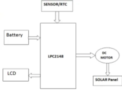
In the block diagram shown in fig.1 shows the complete structure of the tracking system the solar panel is kept on the frame which is rotated by using stepper motor. The stepper motor is connected to the microcontroller. By using the real time clock microcontroller gives the angle to the stepper motor gets rotating as per given angle of inclination.
There are mainly two poles of structure one is stationary and
other is moving. Now by using moving pole we can adjust the axis of rotating panel. The stepper motor is placed at fixed pole.
RTC Real Time
Clock
Microcontroller Unit 8051 based CPU
L293D/ ULN2003 Motor
Driver Unit
Stepper Motor Solar Panels
© 2017, IRJET | Impact Factor value: 5.181 | ISO 9001:2008 Certified Journal | Page 797
Solar Panels
Charge
Controller Unit
DC Battery Unit
Power LED
Bulbs as a
Load
Fig.2 Lighting System
Block diagram of the RTC based solar tracking system.
[image:2.595.40.236.368.514.2]The positional direction of the sun with respect to time has been measured and implemented as an algorithm in the controller. Then, the controller in the chip delivers an output, the corresponding PWM signals, to drive the stepping motors. Thus, the directions of the single dimensional solar platform can be tuned to achieve optimal energy, respectively.
Fig. 3 System Block Diagram
Programmed the controller will constantly peruses the Real Time Clock (RTC) and contrasts and the unthinkable qualities put away, on the off chance that it matches with those qualities the relating positional qualities will be send to the PWM generator which will make the engine to work to pivot sun oriented board to words sun sparkle, By tuning the two dimensional sun oriented stage, the ideal effectiveness of creating force will be accomplished.
START
DISPLAY CURRENT DATE AND TIME
CHECK THE CURRENT TIME
IF CURRENT TIME==6:30:30AM
ROTATE THE PANEL 6" ROTATION USING STEPPER
MOTOR
IF CURRENT TIME==6:31:00AM
ROTATE THE PANEL 6" ROTATION USING STEPPER
MOTOR
IF CURRENT TIME==6:35:30AM
ROTATE THE PANEL TO ZEROTH POSITION USING
STEPPER MOTOR YES
NO
YES YES
NO NO
Fig .4 Flowchart
[image:2.595.311.479.481.606.2]The stepper engines requires a +9V supply and four control beats at its terminals. One stage point of the engine is equivalent to 1.8°. On the off chance that the distinction amongst S1 and S2 is more noteworthy than the blunder, the stepper engine ought to turn forward; if the contrast amongst S2 and S1 is more noteworthy than the mistake, it ought to pivot invert bearing keeping in mind the end goal to keep the level board hitting to body, the board is constrained as vertically with a level of 50° (Figure 5). In this manner, the azimuthally drives can turn on a sum of level of 260° amid day times.
Fig. 5. Limits for movement of the solar panel
© 2017, IRJET | Impact Factor value: 5.181 | ISO 9001:2008 Certified Journal | Page 798
COMPONENTS
1. REAL TIME CLOCK (RTC)
DS1307
64 x 8, Serial, I2C Real-Time Clock
The DS1307 serial constant clock (RTC) is a low-control, full parallel coded decimal (BCD) clock/timetable in addition to 56 bytes of NV SRAM. Address and information are exchanged serially through an I2C, bidirectional transport. The clock/timetable gives seconds, minutes, hours, day, date, month, and year data. The finish of the month date is naturally balanced for quite a long time with less than 31 days, including revisions for jump year. The check works in either the 24-hour or 12-hour arrange with AM/PM pointer. The DS1307 has an inherent power-sense circuit that distinguishes control disappointments and naturally changes to the reinforcement supply. Timekeeping operation proceeds while the part works from the reinforcement supply.
2.LCD DISPLAY
16×2 Liquid Crystal Display which will show the 32 characters at once in two lines (16 characters in one column). Each character in the show of size 5×7 pixel grid.
There are 16 sticks in the LCD module.
3.STEPPER MOTOR
A stepper engine or step engine or venturing engine is a brushless DC electric engine that partitions a full turn into various equivalent strides. The engine's position can then be charged to move and hold at one of these means with no input sensor (an open-circle controller), the length of the engine is precisely measured to the application in regard to torque and speed.
4.SOLAR PANEL
Solar panels get energy from the sun for people to use. Heat from solar panels is often used for space heating and for hot water.
Solar panels collect renewable energy. At the ending of 20th century some panels used the heat of the sun to make steam for a steam engine to turn a generator. Nowadays producing electricity from the sun's light is cheaper.
5.8051 MICROCONTROLLER
The 8051 design gives many capacities (focal preparing unit (CPU), arbitrary get to memory (RAM), read-just memory (ROM), input/yield (I/O), intrude on rationale, clock, and so on.) in one bundle. The gadget additionally has four 8-bit I/O ports, three 16-bit clock/occasion counters, a multi-source, four-need level, settled interfere with structure, an improved UART and on-chip oscillator and timing circuits The gadget
bolsters 6-clock/12-clock mode determination by programming a Flash piece utilizing parallel programming or In-System Programming. What's more, a SFR bit (X2) in the clock control enlist (CKCON) likewise chooses between 6-clock/12-clock mode. Furthermore, when in 6-clock mode, peripherals may utilize either 6 timekeepers for each machine cycle or 12 tickers for each machine cycle. This decision is accessible exclusively for every fringe and is chosen by bits in the CKCON enlist.
SIMULATION MODEL–
Fig. 5 SIMULATION MODEL
3.RESULTS
After fulfillment of equipment of venture there is have to perform test on it to think about his effectiveness To check whether the framework tracks the sun's position precisely, we had keep the sun oriented following framework in open space where daylight accessible for the duration of the day effortlessly and taking the readings of force created hourly. This test is completed independently on two following frameworks level plate & dual hub every day separately. In the wake of watching the readings we have presume that the proposed framework is more effective than other.
Maximum Power Pm (Wp) 100W
Maximum Power Voltage
Vmp (V) 14.0V
Open circuit Voltage Voc
(V) 21.0V
Maximum Power Current
Imp (A) 5.90A
Short Circuit Current Isc (A) 6.35A
© 2017, IRJET | Impact Factor value: 5.181 | ISO 9001:2008 Certified Journal | Page 799 Time
Flat Plate
Single Axis
Dual Axis
Temp. range
°C
6:00 0.02 0.015 0.07 24
7:00 0.061 0.037 15.8 25
8:00 0.65 0.45 19.8 26
9:00 12.5 16.1 25 29
10:00 16.4 17.8 26.6 31
11:00 15.9 16 27.6 33
12:00 16.8 22.2 28.4 34
13:00 13.1 14.5 24 34
14:00 13.9 14.3 22.2 34
15:00 6.5 15.5 21.4 34
16:00 6.5 6 19.6 34
17:00 0.5 0.7 5.8 33
18:00 0.5 3.2 3.58 30
103.331 126.802 239.85
Chart-1:Flat Plate
Chart-2:Single Axis
Chart-3:Dual Axis
Chart-4: Combined Chart
4. CONCLUSION
© 2017, IRJET | Impact Factor value: 5.181 | ISO 9001:2008 Certified Journal | Page 800 tracker is capable of tracking the sun throughout the year.
The dual axis tracker provides higher output power when compared to single axis tracker and fixed panel.
5. REFERENCES
[1] Kenneth Ayala, “The 8051 Microcontroller Architecture, Programming and Applications,” Penram International, 2nd Edition.
[2] S. R. Bull, “Renewable energy today and tomorrow,” IEEE Proc., vol.89, no. 8, pp. 1216-1226
[3] V K Mehta, Rohit Mehta, “Principles of Electronics”, S. Chand & Company Ltd.
[4] J.B.Gupta, “Principles of electrical machines ”
[5] Mohamed Azab, “ A New Maximum Power Point Tracking For Photovoltaic Systems”, International Journal Of Electrical And Electronics Engineering, 2009.