© 2017, IRJET | Impact Factor value: 5.181 | ISO 9001:2008 Certified Journal | Page 18
TECHNICAL OVERVIEW OF ALL SOURCES OF ELECTRICAL POWER USED
IN BTSs IN NIGERIA
Nnoli Kosisochukwu Pal
1, Bolu Jones Ifeanyi
21
Department of Electrical Engineering, University of Rostock, Germany
2
Field Service Engineer (FSE), Maintenance Department, MP-Infrastructure Limited, Nigeria
---***---Abstract -
The power consumption of wireless access
networks have become a major economic and environmental issue in Nigeria. Providing dedicated low cost power supply to off-grid cell sites located in the rural and sub-urban areas in Nigeria is most challenging, as most of the rural areas are not connected to the national electricity grid and, even though they are connected, the availability of the supply is very limited to providing uninterrupted power supply. Base Transceiver Station (BTS), the network security and availability with respect to transmission of radio signals is a direct consequence of power availability on site. Choosing diesel as the main power source for base stations, or as the backup for an unreliable grid, is becoming increasingly hard to justify both economically and environmentally, hence the need to incorporate other sources of power with serious cost considerations geared towards providing adequate and steady power supply to GSM Base transceiver stations (BTS) across the country. This paper is geared towards exposing technically, various electrical power sources and power components used in day to day running of telecommunication sites in Nigeria.
Key Words: Base Transceiver Stations (BTS), Electrical
Power sources, Rectifier, Generators, Automatic Transfer Switch (ATS), e-site, Backup systems, Hybrid Systems and Site maintenance.
1.INTRODUCTION
The telecommunications development in Nigeria since 2001 has been phenomenal. We have witnessed notable and rapid transformation following the liberalization of the communication sector since 2001. This has given rise to the enviable jump in both the number of active subscriptions and tele-densities from the meager 350,000 active lines and tele-density of 0.43 in 2001 to the 150,262,066 active lines and a tele-density growth of 109.65% as of October 2016 with the number of active lines and connected lines clocking a total of 153,514,107 and 230,153,092 respectively and these are expected to continue increasing [1].
This development has necessitated the fast and huge deployment of such related procured equipment and infrastructure/facilities as, Base stations, mast/towers, transmitting antennas, mobile stations, satellite dishes,
microwaves antennas, optical fibres, switching equipment and the power generating sources for both the data and voice transmissions across the country.
In Nigeria, national power grid supply is a major concern and has affected GSM telecommunication operations in terms of costs and reliability. More than half of the sites are off-grid and usually powered by diesel generators with huge operating expenses. The remaining grid-connected sites suffer due to the poor quality of power supply and frequent outages lasting long hours. This has led to a heavy dependence on diesel generators for the grid-connected sites as well.
Subsequently, the operators and tower companies are struggling with unreliable and expensive power for existing networks. Choosing diesel as the main power source for base stations, or as the backup for an unreliable grid, is becoming increasingly hard to justify both economically and environmentally, hence the need to incorporate other sources of power with serious cost considerations geared towards providing adequate and steady power supply to GSM Base transceiver stations (BTS) across the country.
[image:1.595.307.563.486.738.2]© 2017, IRJET | Impact Factor value: 5.181 | ISO 9001:2008 Certified Journal | Page 19
In addition to the poor power grid supply, Nigeriantelecom operators face operation challenges. Site security, for example, is a major issue as there have been several cases of damage to GSM BTS site assets across the country. This risk has hindered GSM service providers from investing in green power alternatives for their network. Misappropriations of equipment and fuel pilfering have affected the overhead operating costs of BTS sites.
Also, initiatives that could have been used in reducing the diesel consumption have been under deliberations due to political and personal interests of some of their staff, thus hampering the successful implementation of these alternatives. The lack of support from the government in providing policy guidelines and security to telecom infrastructure adds to the operational complexity and costs of running a telecom network in Nigeria even though they (Network operators) now provide alternative security men from private security companies for their sites. These outlines have influenced the optimal network operation and quality of GSM service being offered in todays’ Nigeria.
In 2008, the GSM Association (GSMA) gathered nearly 800 worldwide mobile operators to launch a plan for deploying renewable energy sources for 118,000 new and existing base stations in developing countries by 2012 to save 2.5 billion litres of diesel and cut CO2 emission up to 6.3 million tons per year [2]. In Nigeria, Airtel Nigeria (Mobile Operator) has embarked on upgrading 250 diesel powered stations to hybrid sites, the company regretted that non-availability of regular grid power supply to sites across the country is responsible for over 70% of down time, resulting in poor QoS (Quality of Service). Also MTN on the other hand had also budgeted the conversion of diesel powered sites to hybrid power supply system and so far, they have succeeded in achieving a hybrid power solution in nearly 700 sites across Nigeria [3]. Hybrid power system is therefore proposed to proffer solution to the telecommunication diesel consumption level and performance.
A literature review on telecommunication power sources in Nigeria indicates that very little research and analysis has been completed on power loses/failures in Base Transceiver Station due to telecommunication equipment and complexes. Telecommunication outages are automatically reported to the network operating centers (NOC) during mains failure/ blackouts. Blackouts affect many customers and result in power loss over wide geographical area. Technically, a site may be a backbone site, a hub-site or a terminal site. If a backbone site or a hub-site drops on power, it will technically affect all other sites it is hopping as well as the entire hopping links preventing them from transmitting and receiving microwave signals even though the ones on hop are powered themselves. Blackouts are expected to occur. Since such blackouts cannot be completely eliminated, communication complexes must be able to operate on alternate power sources in such an environment taking into
consideration, the comparative advantage within the applied environment.
2. SYSTEM ARCHITECTURE:
Telecommunication electrical power outages occur due to many different reasons, one which is loss of power to the telecommunication equipment. As power outages involves failure of a number of redundant power equipment sequentially leading to a complete power failure in the BTS. It is very important to understand that telecommunication equipment-radios, BTS, antenna, fibre power etc. makes use of -48VDC due to some reasons that will be discussed later in this paper.
The architecture of power grid systems in telecommunication BTS include the national electricity grid system (known as commercial Alternating Current power source), the generator sets (maybe AC or DC in different capacities/ratings), the automatic Transfer Switch system (ATS), Power Distribution Board (DB), Solar Panels or boards, controllers, and chargers, the Rectifiers system (in the case of AC generators), the Back-up Batteries arranged in series, and the corresponding armoured cables, other cables, and breakers. These power infrastructures ensure that electrical power gets to the Base transceiver stations (BTSs) for optimum performance of the site. Telecommunication sites are categorised based on the primary energy source to be used. The three categories are, Mains Power, Solar Power and Hybrid Systems. The selection of primary power source will be dependent on the proximity of mains power, space available for installation of solar arrays and the location of site with respect to support Engineers and/ technicians. They are distributed as follows based on their applications on sites in Nigeria:
1. Base Transceiver Station with only AC Generator
power machine:
This is a Base Transceiver Station power system that has been designed in such a way that it comprises of one or two alternating current generating sets, the Automatic Transfer Switch (ATS), the Rectifier system, Back-up Batteries and the Breakers.
2. Base Transceiver Station with only DC Generator
power machine:
This is a Base Transceiver Station power system that has been designed in such a way that it comprises of one or two direct current generating sets with DC panels, the Automatic Transfer Switch (ATS), the Breakers and Back-up Batteries.
3. Base Transceiver Station with only Hybrid DC
Generator power machine:
© 2017, IRJET | Impact Factor value: 5.181 | ISO 9001:2008 Certified Journal | Page 20
cabinet/shelter or has its own battery cabinet due to size andweight).
4. Base Transceiver Station with only Solar- Battery
hybrid System:
This is a Base Transceiver Station power system that has been designed in such a way that it comprises of Solar panels, chargers, controllers and converters, the Breakers and battery bank directed towards generating DC for BTS use.
5. Base Transceiver Station with a hybrid of DC
Generator, Solar Power System and Back-up
Batteries:
This is a Base Transceiver Station power system that has been designed in such a way that the BTS power is generated by a hybrid and synchronization of a DC generator set, solar power, and back-up batteries. The required current stability is maintained by tapping the input to the BTS from the battery terminals. This type of power solution is always accompanied by E-site solution-an electronic means of monitoring, controlling and maintaining the overall site power performance by ensuring an adequate synchronization of the three power elements-DC generator, Solar and Battery. The above classifications and power requirements for base transceiver stations (BTS) widely vary depending on a number of factors which includes but are not limited to the following considerations:
Is the site indoor or outdoor? Is the site area spacious enough? In which region is the site? Site location
Cost distribution factor
Load considerations at normal operation and also during maximum allowable traffic
Number of Tenants (e.g. MTN, ETISALAT, AIRTEL, GLO, etc)
These variations make it unrealistic to create one load profile for all cell tower power system configurations. There are three different configurations and combinations of renewable and convectional energy sources being deployed for telecommunication purposes in Nigeria today. They are:
Diesel-Battery Solar-Diesel-Battery Solar-Battery
The Customer should provide the following information for the site load before any power supply method is employed:
Operational DC Voltage Peak site load (Watts) Average site load (Watts)
Future planned load (load tolerance)
Site type (A site can be a back-bone site, a hub-site or a terminal site) or classification considering service supported
Site access constraints
Monitoring interfaces and communications protocols to integrate into monitoring systems.
When selecting any deployable power system type/grid type, the following should be considered:
Ease of integration with any existing systems Suitability for use in site environment Ease of transport to and from site Ease of installation
Ease of operation Ease of maintenance
Environmentally sustainable construction (e.g. potential for recycling, etc.)
Below is the schematic diagram of the integrated three types of BTS power sources used in the present day Nigeria.
© 2017, IRJET | Impact Factor value: 5.181 | ISO 9001:2008 Certified Journal | Page 21
The figure 1 represents technical view of the entire powersupply system used today for BTS operation in Nigeria. It is important to state that each power unit or a hybrid of two or more be applied for a sustainable and reliable electrical energy supply to the sites based on the above mentioned factors. Figure 2 also gives a better picture and understanding of the DC generation for BTS operation.
Fig-3: General View of Power System for BTS Operation
When the power from the electrical grid or mains is available, the Power Interface Unit (PIU) selects the best phase of the 3 phase electrical grid and provides power to the rectifier or switched mode power supply (SMPS) via automatic transfer switch (ATS) and Distribution Board (DB). The SMPS converts the 220 VAC to -48 VDC (in some cases to 24 VDC depending on the rectifier rating) providing power to the telecommunication tower equipment and additionally, to charge the batteries as well as float it when it is fully charged.
When the power from the national grid/mains is interrupted, the PIU sends a signal to the generator set to turn on and generator set comes on line in a few minutes to support the entire power requirement at the site. During the transition of supply from the national electricity grid to the generator set, the batteries provide the power required by the telecommunication equipment at the tower and ensure uninterrupted operation of the BTS. Tower owners may use various strategies on how the transition from national electrical grid through batteries to Diesel Generators (DG) works-this switching function is mostly carried out using the automatic transfer switch.
However, there is a need to highlight some of the ideas behind the -48VDC voltage used for BTS operations;
2.1 Why -48VDC (The Sign) for BTS Operation?
Even though many voltage variations and variables are possible; most Base transceiver stations (BTS) loads/equipment run on a -48Volt Direct Current (-48VDC) bus. This practice originated in the early days of telephony, when 48V DC was found to be suitably high for long telephone lines but low enough to prevent serious injury from touching the telephone wires. Consequently, most electrical safety regulations consider DC voltage lower than 50V to be a safe low-voltage circuit. It is also practical, because this voltage is easily applied from standard valve regulated lead acid (VRLA) batteries by connecting four 12V batteries (like those used in cars) in series, making it a simple system. Other factors are as follows:
The battery positive is grounded
Negative Polarity Reduces Corrosion Problems with Underground Cables and Conduits.
2.2 Why -48VDC (The Value)?
The positive grounded or -48V system is another survivor from earlier industry practice. Negative voltage on the line was found to be superior to positive voltage in preventing electrochemical reactions from destroying copper cables if they happen to get wet. Negative voltage also protects against sulphation on battery terminals. Sulphation-the build-up of crystals of lead sulphate, is the leading cause of early battery failure. Other factors are as follows:
AC cannot be easily stored
Low Voltage (less than 74V or 50V) did not require Licensed Electricians
It was not governed by the National Electric Code (NEC)
DC was used to “Carry” voice signals
AC Power was not deemed reliable enough for critical telecom applications
Factors involved in using DC in BTS
Use Multiple Parallel Rectifiers Ease of Expansion
Ease of Redundancy
Higher Equipment and Installation Cost Potentially Lower MTBF of Rectifiers
© 2017, IRJET | Impact Factor value: 5.181 | ISO 9001:2008 Certified Journal | Page 22
Requires Inverters to Power AC Loads 1 Hour Min. Battery due to Coup de Fouet Effect High Power Applications limited by Voltage Drop Power Capacities up to approximately 10,000 Amps
(500 kW)
A typical BTS complex is triply redundant in terms of power. The primary power source is commercial AC/Mains while there are two alternate power supplies-the AC or DC generator, Back-up batteries and solar depending on the deployed configuration. The power system in a communications complex is quite involved as the equipment typically runs on DC. The equipment in these complexes is interconnected in such a way that, when the commercial AC is lost, backup power supplies which include batteries and generators can provide power to all the telecommunications equipment in the complex.
Fig-4: BTS for Out-Door Site
Fig-5: BTS for Indoor Site
The power enters the BTS complex in the form of AC. Almost all communication complexes are provided with AC generators as a backup to Mains/commercial AC. In case of failure of mains/commercial AC, the AC Automatic transfer Switch switches to the generator breaker after it senses the generator is producing nominal AC voltage levels. Most telecommunications equipment in a communication complex requires a DC voltage supply, so the AC power is converted to DC power by Rectifiers. The rectifiers also trickle charge the batteries.
Fig-6: Transmission Radios of a BTS
These batteries provide the required DC power to the equipment in case of failure of both the commercial AC and the AC generator/Solar system. When there is a total power failure or black out, the signalling unit alerts the Network Operations Centre (NOC). If the site is not staffed, the carrier Network Operations Center (NOC) must recognize the alarm and dispatch maintenance team or Engineers to the site in order to power up the site.
Subsequently, the output of the rectifier chamber is fed into the DC distribution panel with variably rated breakers to supply power to the BTS or Optic Fibre equipment. The BTS on powering on, supplies power to radios and then, to the antennas and other devices along transmission.
2.2 Mains/Commercial AC/National grid:
© 2017, IRJET | Impact Factor value: 5.181 | ISO 9001:2008 Certified Journal | Page 23
Fig-7: 100kva Transformer for Commercial AC supply toTelecommunication Sites
In the olden days Nigeria, it was being engineered and controlled by the then Nigerian Electricity Power Authority (NEPA). They later changed their name and became, the Power Holding Company of Nigeria (PHCN). They were in charge of all commercial activity involving power generation by any method, distribution and transmission prior to deregulation.
2.3 AC Automatic Transfer Switch:
If commercial AC is lost, the generators are designed to start automatically and provide the AC power to the communication complex. Upon sensing loss of commercial AC, about 3-4 seconds is required for the generator to start and for the AC voltage to stabilize. Once this is accomplished, a switch brings the generator online. This switch is called the AC Transfer Switch. Some outages occurred because of the failure of the AC transfer switch to perform this critical function. The basic function of ATS is known as synchronization. It synchronizes voltages from different sources to the equipment at a stable and tolerable operating frequency limit.
Fig-8: Automatic Transfer Switch for Voltage Source Synchronization
2.4 Generator Set (AC or DC):
A generator is an internal combustion engine that converts mechanical energy to electrical energy for use in the communication complex. The generator provides electrical power to the communications complex in the event commercial AC power is lost. When this happens, the generator starts automatically (by request from the ATS) and supplies power to the rectifiers. If the generator fails to start for some reason, then an alarm is generated and transmitted to the appropriate NOC and maintenance personnel/team are dispatched to check the cause of failure and at the same time, resolve it.
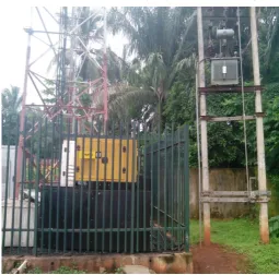
Fig-9: Typical AC Generators on a Telecommunication Site
The generator operates continuously until the commercial AC comes back online or until fuel is depleted or until it fails. Generator capacities/ratings usually used in telecommunication complexes across Nigeria ranges from 6.5KVA (IPT power-Tech) to a maximum of 65KVA (CAT Mantrac/Lista-Peter/FG-Wilson/JubaliBros/Mikano /Younes/Perkins) except otherwise recommended.
2.5 Solar (PV) Panels and
Controller:
© 2017, IRJET | Impact Factor value: 5.181 | ISO 9001:2008 Certified Journal | Page 24
Fig-10: MPPT Solar Charge ControllerFig-11: Solar Panels
Electrical connections are made in series to achieve a desired output voltage and/or in parallel to provide a desired current capability. The preferred solar charge controller type is maximum power point tracker (MPPT) except where noise, system compatibility, relative complexity or cost mitigate against MPPT. Another controller type is pulse width modulated (PWM). The choice of control system is to be made with regard to the size of the DC power system, environmental location of the communications site and other specifications made by International Telecommunications Unit (ITU).
2.6 Power Distribution Board:
A distribution board is an electricity supply system board that divides an electrical power feed into subsidiary circuits, while providing a protective fuse or circuit breaker for each circuit in a common enclosure. A power distribution board takes input from the ATS equipment and supplies power to the individual systems needing it. From power distribution board, power is supplied to HVAC and the rectifier modules for rectification. The Line 1 (L1), Line 2(L2), and Line 3(L3) voltages and contacts can be monitored from the APEX DB equipment shown below.
Fig-12: A Power Distribution Board in a Telecommunication Site
In a telecommunication complex, the output of this board serves as an input to the rectifier modules and subsequently to the SMPS and the HVAC. Every other unconnected breaker stands to provide for future tolerance.
2.7 Circuit Breakers:
© 2017, IRJET | Impact Factor value: 5.181 | ISO 9001:2008 Certified Journal | Page 25
Fig-13: Circuit Breakers on LoadAfter a CB is tripped or fuse is blown, if the BTS complex is not staffed, maintenance personnel must visit the complex to restore AC power by investigating to know why the breaker tripped off and subsequently reset or replace the CB.
2.8 Rectifiers:
Rectifier systems are used to convert the AC power to DC for the communications equipment and to charge the batteries continuously so that they can supply the power to the communications equipment in case of AC power loss. Commercial AC enters the communication complex and is converted to -48V.
Fig-14: -48V and -24V Rectifier modules
Rectifiers also provide the functionality of smoothing any power surges such as those induced by lightning or thunderstorm. Thus they also protect the equipment from sudden changes in voltage or current while DC to DC converters do the rest.
Fig-15: Rectifier Controller module
Rectifiers also provide the functionality of smoothing any power surges such as those induced by lightning or thunderstorm. Thus they also protect the equipment from sudden changes in voltage or current while DC to DC converters do the rest.
2.9 Batteries:
© 2017, IRJET | Impact Factor value: 5.181 | ISO 9001:2008 Certified Journal | Page 26
Fig-16: Battery Strings (Power Backup/DC Storage Systems)If properly designed, built, and maintained, a battery can provide many years of reliable service. A new battery string might not initially provide 100% capacity. The capacity typically improves over the first few years of service, reaches a peak, and declines until the battery reaches its end of life. A reduction to 80% of the rated capacity is usually defined as the end of life for a lead-acid battery. Below 80%, the rate of battery deterioration accelerates, and it is more prone to sudden failure resulting from a mechanical shock (such as a seismic event) or a high discharge rate. Note that even under ideal conditions, a battery is expected to eventually wear out.
3.0 DC Distribution Panel:
A DC distribution panel is used to distribute DC power safely from the rectifiers/battery bank to the communications equipment. Individual DC circuits are routed to individual equipment.
Fig-17: DC Distribution Board of e-site Equipment
Fig-18: DC Distribution board of Rectifier system equipment Each DC circuit is protected by either a fuse or a CB. Fuses/circuit breakers are chosen depending upon the amount of current drawn by the equipment. These breakers blow/open if excess DC power conditions occur. They shut down once they sense over current that is beyond their respective rating/calibration. In the Rectifier system, the DC distribution panel serves as an input to the Base transceiver station and the radios. The main purpose of these devices is to ensure that communications equipment is not damaged.
3.1 Alarm Systems:
Alarms are installed such that when transmission and/ power equipment fails, the failure is automatically detected and an alarm is generated locally, and at the appropriate NOC. If the facility is not staffed, maintenance personnel are dispatched to the location to fix the problem. Alarms should be in place to monitor the generators, batteries, AC transfer switches, Rectifiers and the Circuit Breakers (CBs). There are instances in which the alarm system at the complex is not operative, and as the power loss is undetected, a telecommunications outage results.
Also, solar power arrays, controllers, generators, backup batteries and other components are valuable items and as such theft alarms and security fittings should be provided as specified by the Customer.
© 2017, IRJET | Impact Factor value: 5.181 | ISO 9001:2008 Certified Journal | Page 27
A typical telecommunication power unit should have some orall of the following system monitoring/alarms depending on the site build-ups:
Synchronization failure alarm Low input voltage shutdown alarm High temperature alarm
Intruder alarm
Speed request failure alarm Underspeed alarm
Rectifier failure alarm Overvoltage alarm
Circuit breaker failure alarms LVD1 and LVD2 action alarm Power failure alarm
generator start failure alarm fuel low limit alarms
Oil pressure alarm Battery flat alarm
The provision of these alarms (generally referred to as the Mains failure alarm) on site ensures prompt attendance to any problem on site and delivers 24 hours barely uninterrupted power supply to the BTSs on sites across Nigeria.
3.2 Hybrid Systems:
A typical hybrid power system uses a combination of solar and at least one other power source to provide sufficient power to supply the load and recharge the batteries. The components form an integrated system with system controller to provide a continuous DC supply while ensuring battery charge is within required limits (providing float charge after the batteries are fully charged). The standard configuration utilises an AC or DC diesel generator as the complimentary power source.
Fig-20: A typical hybrid solution (12kw DC generator and 6kw Solar system)
The generator in a hybrid system contributes to the supply of standard load. E-site hybrid power system is a typical organization of power equipment used to provide 24 hours uninterrupted power supply to BTSs in Nigeria provided that it works under normal design and operating conditions.
4. THE E-SITE/FLEXENCLOSURE
eSite is a fully integrated hybrid power system for telecom sites that cuts diesel costs by up to 90%. eSite can work as a diesel-battery hybrid, or with any combination of grid or renewable energy sources and diesel generator backup, to provide reliable, cost efficient power in areas where mains electricity is either unreliable or unavailable. eSite is a single cabinet solution, specifically designed for powering base stations. Every component has been selected for this purpose and it is all controlled by Diriflex™ – Flexenclosure’s patented intelligent power management system. Diriflex controls eSite’s adaptive charging strategy, and ensures that as much energy as possible is extracted from the available sources while keeping energy losses low.
It optimally balances the combination of battery lifetime and diesel generator run-hours to ensure the best economic result. It is a fully integrated and optimised site power solution that can deliver a 90% reduction in diesel fuel consumption and Carbon monoxide (CO) emissions. The main focus or reason why e-site power supply is mostly employed in Nigeria is to generally cut a great deal of cost and still maintain at least 99.6% performance as underperformance is highly un-recommended and attracts great loss to the site manager.
4.1 How esite works: Solar energy:
eSite makes maximum use of sunlight by using advanced charging algorithms and energy source prioritisation with a solar controller with MPPT (Maximum Power Point Tracking) on solar panels and 99% efficiency.
Unreliable grid
An unreliable power grid at the site can efficiently be used as a power source even if the grid power varies in both voltage and phase. Diriflex Grid Manager controls it all and makes sure uptime is never jeopardised.
Generator
eSite minimises diesel consumption by using the genera-tor at maximum efficiency to charge the batteries quickly. When renewable energy sources are also available, the generator is only used as a backup.
eManager
© 2017, IRJET | Impact Factor value: 5.181 | ISO 9001:2008 Certified Journal | Page 28
DiriflexThe brain of eSite, Diriflex optimises the use of batteries and all energy sources to lower diesel consumption, while prolonging the lifespan of the batteries and other components. It is known as Sam2.
Battery bank
eSite’s adaptive charging algorithms minimise generator use regardless of whether the eSite is being run as a diesel-battery hybrid or with other energy sources. The Diriflex controlled charging strategy ensures longest possible battery life.
Diriflex Grid Manager (DGM) controls and optimises the use of any available grid power, regardless of its stability or voltage, thus radically reducing the cost of running sites. It is extremely powerful in reducing the cost of running a site even when grid uptime is limited and sporadic. DGM maximises grid usability. It can cope with voltage variations from 85 to 300V and frequencies from 45 to 65Hz. And it can still charge the batteries even if one or two phases are not available. It is “system aware”, constantly monitoring battery charge levels, such that in the case of grid failure it knows whether to switch to the battery bank or to start the generator [4].
Fig-21: A physical view of Flexenclosure e-site Equipment
There are three models of eSite available, viz[4]:
The Site k2, eSite k4 and eSite k10. eSite is modular and can be tailored to suit any and all local site conditions:
• eSite k2 supports up to 2kW site load • eSite k4 supports up to 4kW site load • eSite k10 supports up to 10kW site load
Note: the above said function and use of eSite/flexenclosure is technically correct and can perform maximally only if it is working perfectly as designed/predicted. Otherwise, other power solutions can be employed with a strong design focus on economics.
5. AN OUTLINE ON SITE MAINTENANCE AND
MANAGEMENT
5.1 Maintenance:
This is a group of calculated tasks and strategies designed and implemented by a specialized company to offer this type of service to Mobile Phone companies that have, as a result, a low impact in problems caused by damage, wear out or rupture of backup components of a Telecom site and equipment which may interfere with the reception and transmission of radio waves for the purpose of communication through the installed equipment and links. Maintenance may be preventive or corrective; it can also be passive or active.
Maintenance services for the Telecom Cell Site include: • Preventive Maintenance and Non-preventive Maintenance
• Diesel Filling & EB Payments
These also includes provision of DG maintenance, diesel filling, maintenance for AMF Panel, UPS, Fire Alarm System, FMC, NMS, follow up for alarms, order wire, battery voltage, level of distilled water in the secondary cells, battery charger and electrical installation of the prefabs / building and in case of any discrepancy report it to etc.,
• Preventive Maintenance services as per the service level agreement/statement of work (SLA / SOW)
• Corrective Maintenance
• DG servicing, AC servicing and over hauling in accordance with the specification by OEM / Customer.
• Break down Maintenance like tracking of Alarms for site outages and link failures.
• Diesel filling according to ensure the availability of HSD in the DG tank.
Active maintenance on the BTS and antenna system include: • Radio Power Management
© 2017, IRJET | Impact Factor value: 5.181 | ISO 9001:2008 Certified Journal | Page 29
• Verification and correction of Connectorization of RF/ IF cables
• Validation of antenna orientations and corrections if required to meet up with the LOS pattern.
5.2 Passive Maintenance services cover the
following Telecom Infrastructure:
• Power Plant • Diesel Generator
• PMU (Power Management Unit) • Fire Alarm System
• Battery Bank • Air Conditioners • Shelters
• Servo Stabilizers • SMPS
• Tower / Mast / Pole • Earth Pits
• Other Electrical Elements
5.3 Optic Fibre Cable(OFC) Network Maintenance
• Preventive and Corrective Maintenance is carried out as defined by the SLA / SOW
• All fibres are tested for the block sections and reported every month
• Patrolling is aimed at preventing cable disruptions along the OFC routes daily on fixed fibre link
• Any defects in the fibre or in any of the associated equipment is attended to, in consultation with the Customer at site
• Repeater stations and the optical equipment installed for alarms are monitored by the NOC
• Breakdown OFC Maintenance includes 24*7 mobilization of equipment and skilled manpower for fault identification and rectification
• Test link attributes like the splice loss/link loss after the rectification of fault are corrected
• Deployment of O&M teams to carry out Splicing and Termination of Optical Fibre Cable.
6.0 Conclusion:
This paper has succeeded in highlighting the successes already met by some of the Nigerian telecommunication tower owners and site managers in the area of power supply to base transceivers stations. It is no doubt a clear technical overview of how electrical power is being generated and distributed within a typical telecommunication complex in Nigeria. However, efforts and competitions are still ongoing between tower owners (IHS Africa-Tower of strength, American Towers, Huawei, Helios Towers Nigeria (HTN)) and site managers (MP-Infrastructure, Linksoft, Biswal, Petroseal, Makassa, ZTE, Emerson Networks, Nokia, etc.) directed towards ensuring that the diesel consumption rate of telecommunication sites are brought to the lowest minimum considering the economic situation of Nigeria if they are to remain in business. More so, knowing fully well that the majority of down-time (high Mean time between failure-MTBF) or site down experienced across Nigeria is as a result of power failure, critical research should continue, directed towards discovering and deploying alternative, cheaper and sustainable energy sources and grids for use in telecommunication complexes across Nigeria.
ACKNOWLEDGEMENT
We (the authors) wish to acknowledge Mr. Nnoli Okechukwu, who inspired this research from its early stage. Our unalloyed thanks go to the MP-Infrastructure Limited , MTN Nigeria, HUAWEI Nigeria and ETISALAT Nigeria for their time and resources that aided this research and also to everyone who contributed in no small measure to the success of this paper at this time.
REFERENCES:
1. Nigerian Communications Commission, Annual Publication on monthly Subscribers Statistics, July 2015 to October 2016,
http://www.ncc.gov.ng/stakeholder/statistics- reports/subscriber-data#monthly-subscriber-technology-data / visited on 26/11/2016.
2. M. Vincenzo and S. Alouf, S. Inria, M.A. Sophia, Reducing Costs and Pollution in Cellular Networks, IEEE Communication Magazine August, 2011.
3. N. Faruk, A. A. Ayeni, M. Y. Muhammad, A. Abdulkarim, O. Moses, Hybrid power systems For Cell Sites In Mobile Cellular Networks, Cyber Journals: Multidisciplinary Journals in Science and Technology, Journal of Selected Areas in Renewable and Sustainable Energy (JRSE), January Edition, 2012.
4.Flexenclosure-Brochure;
© 2017, IRJET | Impact Factor value: 5.181 | ISO 9001:2008 Certified Journal | Page 30
BIOGRAPHIES:
Nnoli Kosisochukwu Pal graduated from the Department of Electronic and Computer Engineering of the Nnamdi Azikiwe University, Awka. He was a Support Engineer at Redington Nigeria (a subsidiary of Redington Gulf). He was also a Drive test Engineer at Spectrum Comms Ltd as well a Field Service Engineer with MP-Infrastructure Limited. He is currently running his post-graduate studies in Electrical Power Engineering at the University of Rostock, Germany. A member of IEEE, IAENG, NSE, NSBE, NIM (Chartered). His research interests spans across telecommunication power sources, expert systems, Power systems and machines, Renewable Energy and Energy Conversions.
Jones Bolu Ifeanyi graduated from the Department of Electrical Electronics Engineering (Power Systems) of the Federal University of Technology, Owerri. He was an Engineer with Power Holding Company of Nigeria. He is a Field Service Engineer with MP-Infrastructure LTD. He is currently seeking for a Post-graduate Program in Electrical Electronic Engineering at a recognized University in Germany. A member of IEEE, NSE, SEEES. His research interests spans across Power Systems-and-Machines,
Telecommunication power sources, Expert Systems, Electrical Power/Energy-Generation, Renewable Energy and Energy conversion.