106
WALL-FOLLOWING USING A KINECT SENSOR FOR
CORRIDOR COVERAGE NAVIGATION
1MUHAMMAD FUAD, 2DJOKO PURWANTO 1Faculty of Engineering, University of Trunojoyo Madura, Indonesia
2Electrical Engineering Department, Faculty of Industrial Technology, Institute of Technology Sepuluh
Nopember Surabaya, Indonesia
E-mail: [email protected] , [email protected]
ABSTRACT
Navigation system based on Kinect sensor for wall-following robot that operated in stright corridor environment consist of two problems, visual perception to get the distance to border of the corridor, and velocity control of the robot. Schema, scenario, methods, and experiments to answer those problems using only a single sensor was explained in this publication.
Keywords: VisualNavigation, Kinect Sensor, Wall-Following, Stright Corridor.
1. INTRODUCTION
Service robots plays an important role in robotics application with demand growth in market as stated in report of RoboNED using data provided by Japan Robotics Association [1]. More than two-thirds of total amount of robotic market will be fulfilled with service robots. One of keyplayer in this sector of robotics is vacuum cleaner robot. A cleaning robot has to cover as much as area in the workspace environment to perform it’s task. Choset in [2] classified algorithms in this field into some categories included heuristic. An approach to implement heuristic algorithm for coverage can be achieved by equipping a robot with behaviour such as wall-following along with simple back and forth motions.
Wall-following robot usually use combination of distance sensor and compass for navigation purpose. Sensor for measuring the distance of obstacles, such as infrared, or ultra sonic sensor, have been investigated in [3] and [4] respectively. Both research only focus on position control of robot without consider how to correct orientation error. Micro-gyro-compas have been studied in [5] and [6] to maintain heading angle of robot. Although both research have used combination of some sensors but still they have to struggled with how to control the heading efficiently. This research proposes an approach to substitute distance sensor and compass by using only one Kinect sensor as an efficient way to navigate a vacuum cleaning robot inside stright corridor. Kinect sensor, definitely
known as a game pheriperal, was adjusted to be a multi functional sensor to provide the capability of distance measurement and heading estimation.
The paper is organized as follows. Section 2 describes robotic platform that is used in this research. The proposed navigation system design is presented in Section 3. Section 4 explains the technique that is used for measuring the distance of obstacles. The method of heading estimation is described in Section 5. Section 6 reports the experimental results of wall-following algorithm based on distance and heading estimation using Kinect Sensor. And finally, some concluding remarks is stated in Section 7.
2. ROBOTIC PLATFORM
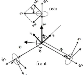
[image:1.595.338.474.607.729.2]Kinematics diagram of omnidirectional three wheel robot as a platform to carry out vacuum cleaning task is shown in Figure 1.
Figure 1: Kinematics Diagram of Omnidirectional Robot rear
107 Kinematical model as described in Formula (1) must be known in order to control this plant.
∅
ࡸ
ࡸ
∅
ࡸ
ࡸ
∅
ࡸ
ࡸ
(1)
where ∅ଙ describes rotational velocity of each
wheel; r represents radius of each wheel; θ is orientation of the robot; α is angle of each wheel relative to local frame measured from the first wheel; and are global velocity of robot in x
and y frame respectively; R is the distance from the center of gravity of the robot to the wheel; and represents rotational velocity of robot. According to Formula (1), motion control of the robot can be realized by controlling for back – forward
translational motion, for left – right translational
motion, and for rotational motion.
[image:2.595.307.505.258.450.2]Kinect sensor and laptop are positioned in the rear part of robot above the first wheel. Sensor is at 90 cm height from floor surface. Tilt angle of sensor is set in 0 º. Vacuum cleaner machine is put at the center of gravity of robot. Sucker aparatus is set between the second and the third wheel. This part is 40 cm width. Battery and microcontroller are set below vacuum cleaner machine. Physical dimension of robot is displayed in Figure 2.
Figure 2: Physical Dimension of Robot.
3. NAVIGATION SYSTEM DESIGN
[image:2.595.90.285.593.722.2]In order to realize wall-following behaviour, robot has to maintain it’s distance with the wall while moving forward. This will be need two abilities. First, the ability to measure the distance between itself with the wall. When drifting error happens it should be corrected with the ability to estimate the heading. Based on these requirements, visual navigation system using only one Kinect Sensor is designed as shown in Figure 3.
Figure 3: Block Diagram of Visual Navigation System
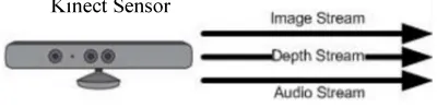
According to technical reference from Microsoft Research [7], Kinect sensor provide two image stream data and one audio stream as illustrated in Figure 4. RGB image stream with 640 x 480 and Depth stream with 320 x 240 in resolution. Both stream provide 30 frames per second. This sensor has viewing angle 43º in vertical and 57º in horizontal. Since it is designed for game-playing, this sensor has playable range between 120 to 350 cm. Depth stream contains information about the distance of each objects that reflects the infra red projection from sensor. Distance measurement block has to be provide this information as input for velocity control. Heading angle estimation block use image stream to provide input to control orientation.
Figure 4: Data Stream from Kinect Sensor Battery &
microcontroller
Depth Image stream
RGB Image stream
Distance measurement
Heading angle estimation
Velocity control
Orientation control
Motion control
[image:2.595.305.505.679.728.2]108
4. DISTANCE MEASUREMENT
[image:3.595.303.510.201.398.2]There are three circles in the front part of Kinect sensor. The first one is infra red projector. The second one is RGB camera. And the last is infra red camera. Distance is measured by projecting infra red and capture the reflection. Using Aforge framework for reading depth stream from Kinect sensor resulting depth image as shown in Figure 5. These two images are captured indoor with different condition. The left one is image of a white box with distance 80 cm from sensor. And the right one is captured by changing the distance of the same object to 560 cm. Figure 5 represents the range of the distance that can be sensed by Kinect is in between 80 and 560 cm. Object that stands closer or more far than this range will be displayed as black pixels.
Figure 5: Depth Image Contains Distance Information
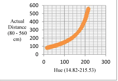
[image:3.595.115.262.339.407.2]By recording 263 samples with precision 10 cm, relationship between hue value of depth images and actual distance of object can be mapped as presented in Figure 6.
Figure 6: Relationship between Hue and Actual Distance
This research proposes a method to convert hue value to get distance information by using piece-wize exponential as wroten in Formula (2).
Hue Actual
(cm)
Piece-wize Exp
0 – 59 80 – 100 0,72 * EXP * (0,007 * hue)
60 – 144 100 – 200 0,67 * EXP * (0,008 * hue)
(2)
Table 1 shows some values of distance measurement using Formula (2) that are compared to actual distance. For range distance between 80 to 560 cm, total average error 1.14%.
Table 1: Comparison between Actual Distance and Measurement Based Formula
No. Hue (14.82-215.53)
Actual (cm)
Formula (cm)
Error absolute (cm)
Error absolute (%)
1 14.82 80 79 1 1.25%
2 72.47 120 119 1 0.83%
3 109.65 160 161 1 0.63%
4 136.47 200 199 1 0.50%
5 155.53 240 239 1 0.42%
6 169.65 280 279 1 0.36%
7 179.76 320 322 2 0.63%
8 188.47 360 370 10 2.78%
9 196.71 400 395 5 1.25%
10 202.12 440 431 9 2.05%
11 206.12 480 489 9 1.88%
12 211.53 520 520 0 0.00%
13 215.53 560 547 13 2.32%
Average Error ( % ) 1.14%
[image:3.595.90.287.485.621.2]Actual distance between robot and wall of the corridor can be measured from center of gravity of robot perpendicular to wall. The value is equal to cosine of complement angle by distance measurement from Kinect to the wall with respect to viewing angle parameter. This approach is illustrated in Figure 7.
Figure 7: An Approach to Measure Actual Perpendicular Distance from Robot to the Wall
0 100 200 300 400 500 600
0 100 200 300
Actual Distance (80 - 560
cm)
Hue (14.82-215.53)
Kinect
60°
wall
80 cm 560 cm
corridor
α
90º - α
[image:3.595.325.475.503.710.2]109
5. HEADING ANGLE ESTIMATION
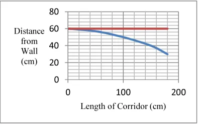
[image:4.595.89.288.270.398.2]Friction forces on the gear and motor shaft are considered as major cause to drifting error. When this error happened, heading direction of robot did not align with corridor axis as shown in Figure 8. Stright line with red color represents setting point of distance from wall that set in 60 cm as ideal robot trajectory. Robot should move forward with maintain this distance. While drift error happened, robot trajectory can deviate from red line to curved line with blue color.
Figure 8: Drift Error Changes Heading Direction of Robot
The problem is how to define heading angle of robot while it move in the corridor. When robot is facing the corner of corridor such as illustrated in Figure 9(a), there is a point that can be used as a heading guidance. In this case, the point where corner of corridor exist is established as direction that robot should go. In prespective ways, from this point, a number of lines can be draw until four corners of image. This heading point is known as vanishing point.
[image:4.595.106.275.637.706.2]Using Hough transform algorithm, lines can be extracted from the image such as displayed in Figure 9(b). Some red lines in this figure may appear from border line between floor and fences, border of door, border of fences, and between ceiling and wall.
Figure 9: Drift Error Changes Heading Direction of Robot
Extracting Hough lines are expensive in its computation. RGB image 640 x 480 in resolution is resized to 78 x 78. This small size image is divide into 3 x 3 cell in order to run Hough transform in each cell. This approach guarantees each cell produce maximum one line with the highest intensity. Extending these lines from one side to the other side of images may result some intersections in order to get vanishing point. Unfortunately, as shown in Figure 10(a), one or more candidate vanishing points may appear as result of some intersections that could happen. In this figure, blue lines are extended Hough lines intersect each other into some vanishing points that appear as red circles. There are some steps that this research proposed to get ride fake vanishing points.
Since tilt angle of sensor is set to 0º, valid candidate vanishing points can be found only in the middle of image. In the other words, vanishing points that appear outside this partition are fake.
Vanishing point has a unique characteritic as the furthest position with respect to perspective. In the depth image, the furthest objects represent in black color as displayed in Figure 10(b). Using this principle, valid vanishing points should appear as black pixels in depth image. By synchronizing candidate vanishing points that extracted from RGB image with principle of furthest objects appear as black pixel, valid vanishing points can be resulted.
When some vanishing points could be found, the valid one should be intersected by as much as existing lines. If there are some valid vanishing points then it must be count to find the average. Figure 10(c) displays single valid vanishing point represents as yellow circle.
[image:4.595.319.491.643.709.2]Vanishing point that arise at some position in middle row cells can be percepted as heading angle with respect to 57º of viewing angle in horizontal. By dividing image into two columns, the middle is set to 0 º, the right part represents positive degree, and the left part represents negative. Using this approach, vanishing point in Figure 10(c) is percepted as heading angle in 2º.
Figure 10: Towards Extracting Single Valid Vanishing Point
0 20 40 60 80
0 100 200
Distance from Wall (cm)
Length of Corridor (cm)
110 Table 2 is displayed comparison between actual and estimation of heading angle.
Table 2: Comparison between Actual and Estimated Heading Angle.
θactual θestimate Abs_error
-15 -12 3
-10 -9 1
-5 -5 0
0 -1 1
5 4 1
10 9 1
15 13 2
θaverage_abs_error 1.43
6. EXPERIMENTAL RESULTS
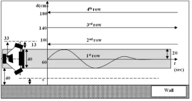
[image:5.595.317.498.193.435.2]Experiment to test the visual navigation system to do wall-following with back-forward movement for coverage in corridor area using scenario that is illustrated in Figure 11. Robot position is set in stright corridor that has 233 cm in length. The first path that robot should do wall-following is at 60 cm from the wall. It will spare 17 cm as safe distance and 7 cm as critical safe distance in order to avoid wall crashing. The gray block in this figure represents the area should cover by sucker aparatus that has dimension 40 cm. Using this coverage dimension, next path will be 100 cm, 140 cm, and 180 cm from the wall. Sinusoidal shape illustrates drifting error that should compensate by maintaining distance from the wall and correcting wrong direction of heading.
Figure 11: Experiment Scenario of Wall-Following for Coverage in Corridor.
Motion control consits of velocity and orientation control using fuzzy set with design as shown in Figure 12 and Figure 13. Velocity control processes two input, error and delta error of difference between ideal and actual current distance. Output of this controller is velocity in
± 0,2 m/sec.
Orientation control processes two input, error and delta error of difference between ideal and actual current heading angle. Output of this controller is velocity in ± 0,5 rad/sec.
Figure 12: Design of Fuzzy Set for Velocity
Control.
[image:5.595.315.498.467.709.2] [image:5.595.94.287.522.624.2]111 The ideal trajectory is displayed in red color as shown in Figure 14. The actual trajectory had been recorded and displayed in blue color. Robot starts following a wall at 0.6 m distance to its right side. Robot can keep this distance from 0 to 2 m but drifted to the left until 7.2 m. In transition phase, robot move from the first path to the second. It can reach ideal path within 2.25 m and maintain to align with wall in 1.0 m distance to its left side. Robot in hard situation when it move from the second path to the third. Ideal path, 1.4 m distance from wall to its right side, can be reached at 5.8 m and keep align until end of path. In the last path, robot keep wall following align with 1.6 m distance to its left side rather than with 1.8 m as planned. This is happened because of the limitation of Kinect sensor.
Figure 14: Actual and Ideal Trajectory in Wall-Following for Coveraging Corridor.
7. CONCLUSIONS
A navigation system for wall-following behaviour in performing coverage in stright corridor based on single Kinect sensor has been presented. The position and orientation of the robot are estimated using only one sensor. Distance measurement is implemented by percepting hue value of depth image to actual distance using piece wize exponential formula with 1.14% in average error. Hough transform is applied in partitioned RGB image synchronize with depth image in resulting single valid vanishing point that can be percepted as heading angle with 1.43 in average error. Motion control based on fuzzy with distance measurement and heading angle estimation as input has been successfully control the robot to follow the wall for coverage in corridor with respect to limitation of sensor.
This method has weakness when it is used in outdoor environment since sensor will return black image and cannot differ between objects in close or far distance. For future research, we will investigate an approach to use Kinect sensor in outdoor corridor.
REFERENCES:
[1]. D. Kranenburg, “Dutch Robotics Strategic Agenda: Analysis, Roadmap & Outlook”, Lpskamp Drukkers, Enshede, The Netherlands, June 2012.
[2]. H. Choset, “Coverage for Robotics – A Survey of Recent Results”, Annals of Mathematics and Artificial Intelligence 31: 113 - 126, Kluwer Academic Publishers, Netherlands, 2001.
[3]. I. Gavrilut, V. Tiponut, A. Gacsadi, and L. Tepelea, “Wall-following Method for an Autonomous Mobile Robot using Two IR Sensors”, 12th WSEAS International Conference on SYSTEMS, Heraklion, Greece, 2008.
[4]. A. Imhof, M. Oetiker, B. Jensen, “Wall Following for Autonomous Robot Navigation”, 2nd International Conference on Applied Robotics for the Power Industry, ETH Zurich, Switzerland, September 2012.
[5]. J. Serres, F. Ruffier, S. Viollet, N. Franceschini, “Toward optic flow regulation for wall-following and centring behaviours”, International Journal of Advanced Robotic Systems, Vol. 3, No. 2, 2006.
[6]. F.L. Roubieu, J. Serres, N. Franceschini, F. Ruffier, S. Viollet, “A fully-autonomous hovercraft inspired by bees: wall following and speed control in straight and tapered corridors”, 2012 IEEE International Conference on Robotics and Biomimetics, Guangzhou, China 2012.