http://www.scirp.org/journal/cs ISSN Online: 2153-1293
ISSN Print: 2153-1285
Open Source Synthesis and Verification
Tool for Fixed-to-Floating and
Floating-to-Fixed Points Conversions
Semih Aslan1, Ekram Mohammad1, Azim Hassan Salamy2
1Ingram School of Engineering, Electrical Engineering Texas State University, San Marcos, Texas, USA 2School of Engineering, Electrical Engineering University of St. Thomas, St. Paul, Minnesota, USA
Abstract
An open source high level synthesis fixed-to-floating and floating-to-fixed conver-sion tool is presented for embedded design, communication systems, and signal processing applications. Many systems use a fixed point number system. Fixed point numbers often need to be converted to floating point numbers for higher accuracy, dynamic range, fixed-length transmission limitations or end user requirements. A similar conversion system is needed to convert floating point numbers to fixed point numbers due to the advantages that fixed point numbers offer when compared with floating point number systems, such as compact hardware, reduced verification time and design effort. The latest embedded and SoC designs use both number systems together to improve accuracy or reduce required hardware in the same design. The proposed open source design and verification tool converts fixed point numbers to floating point numbers, and floating point numbers to fixed point numbers using the IEEE-754 floating point number standard. This open source design tool generates HDL code and its test bench that can be implemented in FPGA and VLSI systems. The design can be compiled and simulated using open source Iverilog/GTKWave and verified using Octave. A high level synthesis tool and GUI are designed using C#. The proposed design tool can increase productivity by reducing the design and veri-fication time, as well as reduce the development cost due to the open source nature of the design tool. The proposed design tool can be used as a standalone block genera-tor or implemented into current designs to improve range, accuracy, and reduce the development cost. The generated design has been implemented on Xilinx FPGAs.
Keywords
FPGA, VLSI, RTL, Iverilog, GTKWave, OCTAVE, HLS, C#, Open Source How to cite this paper: Aslan, S.,
Mo-hammad, E. and Salamy, A.H. (2016) Open Source Synthesis and Verification Tool for Fixed-to-Floating and Floating-to-Fixed Points Conversions. Circuits and Systems, 7, 3874- 3885.
http://dx.doi.org/10.4236/cs.2016.711323
Received: May 18, 2016 Accepted: May 30, 2016 Published: September 23, 2016
Copyright © 2016 by authors and Scientific Research Publishing Inc. This work is licensed under the Creative Commons Attribution International License (CC BY 4.0).
http://creativecommons.org/licenses/by/4.0/
1. Introduction
Most embedded systems, System-on-Chip (SoC) and transmission systems are imple-mented using either fixed point, floating point or hybrid number systems wherein fixed [1] [2] and floating point numbers [3] [4] can be used together in the same chip [5]-[7]. The IEEE754-1985 standard was released for binary floating point arithmetic with some new features such as better precision, range and accuracy [8]. The current standard in-cludes half precision, single, double, double-extended and quadruple precisions [8].
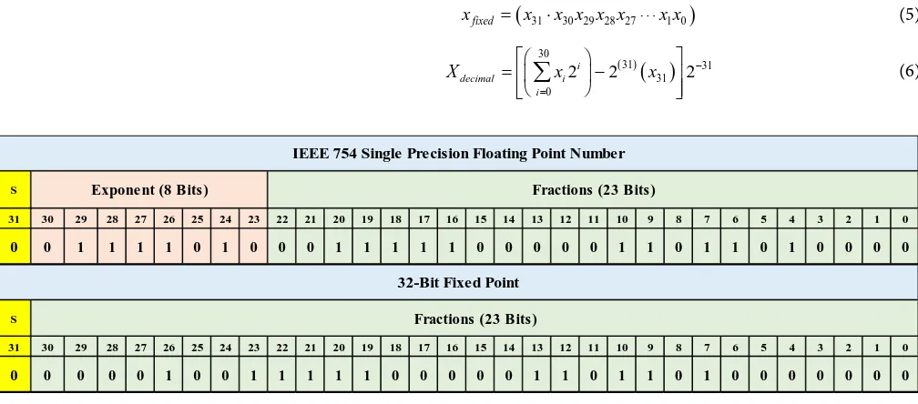
The single precision binary 32-bit floating and 32-bit fixed point numbers are shown in Figure 1. The most significant bit (index number 31) of the floating point number is the sign bit. The next eight bits are biased exponents (index numbers 30 - 23) and the last 23 bits are fraction bits [8]-[10]. The representation and decimal calculation of the single precision floating-point number are shown in Equations (1) and (2), respectively:
( ) (
)
( 127)22 21 20 19 1 0
1 s 1 2
float
x = − ⋅x x x x x x ε− (1)
( )
22 ( )127 23
0
1 s 1 2i 2
decimal i
i
X x − ε−
=
= − +
∑
(2)The 32-bit fixed point number that is shown in Figure 1 has an integer signed-fixed point number and its decimal equivalent is shown in Equations (3) and (4), respective-ly:
(
31 30 29 28 27 1 0)
fixed
x = x x x x x x x (3)
( )
( )
3031 31 0
2i 2 decimal i
i
X x x
=
= −
∑
(4)The numbers that are used in many DSP and communication systems are scaled be-tween [−1, 1). The [−1, 1) scaled version of equations (3) and (4) can be written as Eq-uations (5) and (6) respectively:
(
31 30 29 28 27 1 0)
fixedx = x ⋅x x x x x x (5)
( )
( )
3031 31
31 0
2i 2 2
decimal i i
X x x −
=
= −
[image:2.595.47.551.470.692.2]
∑
(6)Figure 1. IEEE 754 floating and 32-bit fixed point numbers. S
31 30 29 28 27 26 25 24 23 22 21 20 19 18 17 16 15 14 13 12 11 10 9 8 7 6 5 4 3 2 1 0
0 0 1 1 1 1 0 1 0 0 0 1 1 1 1 1 0 0 0 0 0 1 1 0 1 1 0 1 0 0 0 0
S
31 30 29 28 27 26 25 24 23 22 21 20 19 18 17 16 15 14 13 12 11 10 9 8 7 6 5 4 3 2 1 0
0 0 0 0 0 1 0 0 1 1 1 1 1 0 0 0 0 0 1 1 0 1 1 0 1 0 0 0 0 0 0 0 Exponent (8 Bits) Fractions (23 Bits)
Fractions (23 Bits)
IEEE 754 Single Precision Floating Point Number
The hardware implementation of fixed point number systems requires less hardware than floating point number systems. The implementation of addition in a floating point number system can be particularly difficult and will consume more hardware than fixed point numbers. Fixed point numbers are limited to the number of bits used as shown in Figure 1. For example, representing the current U.S. National debt, which is 19,246,968,550,852 dollars [11], requires 45-bit fixed point number system. Representing the same debt in Mexican pesos, which is 337,858,398,896,373, requires a 49-bit fixed-point number system, and 44,385,703,632 bit coins require a 36-bit fixed point number system. These numbers can be represented using single precision 32-bit floating numbers 0 × 558C0A46, 0 × 5799A3E5, and 0 × 51255981, respectively. Another advantage of a floating-point number system is in the representation of small-er numbsmall-ers [9]. For example, the charge and mass of a proton are 1.60217646 × 10⁻¹⁹C and 1.6726219 × 10⁻²⁷ kg, which can be represented as 32-bit floating point numbers as 0 × 203D26D0 and 0 × 130484CD, respectively. The error during this representation is 3.9999 × 10⁻²⁷. To represent the charge of a proton using a fixed-point number system [12], an 80-bit is required. Error during this representation is 6.5653 × 10⁻²⁵. To reduce this error, the number of bits needs to be increased to 88-bit. This error is reduced to 3.4346 × 10⁻²⁵. This shows that floating point numbers offer better dynamic range.
To improve design accuracy, improve range and reduce design time and cost, a cus-tom fixed-to-floating and floating-to-fixed-point conversion tool is proposed. This conversion tool is described in Section 2. FPGA implementation and results are dis-cussed in Section 3, and the conclusion and future work are given in Section 4.
2. Fixed-to-Floating Point Conversion System
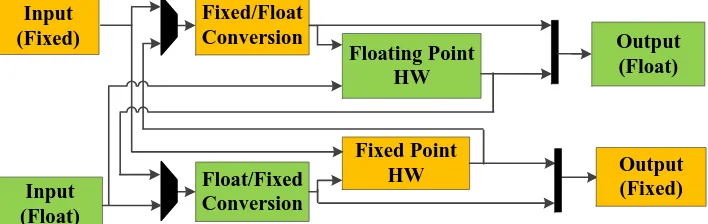
Most hardware blocks in the latest processors, microcontrollers, microprocessors, and many special purpose arithmetic logic units (ALU) use fixed and floating point arith-metic operations. Some of these hardware blocks need to communicate with each other or I/O needs to be represented in either fixed and/or floating point numbers. Fixed-to- floating and floating-to-fixed point conversion blocks are often needed to properly transfer the data as seen in Figure 2 below. Designing and verifying these blocks could be time consuming and require a longer time-to-market (TTM) cycle.
[image:3.595.197.551.571.683.2]The proposed conversion tool shown in Figure 3 can accelerate TTM [13] by reduc-
Figure 2. Conversion blocks communication.
Output (Fixed) Input
(Fixed)
Input (Float)
Float/Fixed Conversion Fixed/Float Conversion
Floating Point HW
Fixed Point HW
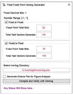
Figure 3. Fixed-to-floating point conversion GUI.
ing the verification time if IEEE-754 floating point or custom floating point arithmetic are required. The GUI of the proposed the conversion system is developed in C# with Window Presentation Foundation (WPF). The developed software is inherently ex-ecutable in every Windows PC running Windows 7 or greater. The software does not require any special runtime except .NET, which is available in every Windows PC. The GUI incorporates the Model-View-View Model (MVVM) model for improved interac-tion and easy user interface. It is modular, refactorable and easily extendable. The GUI code and the logic are separated via MVVM model so that developing UI does not in-terfere with the main aspect of the software.
This conversion tool takes an n-bit fixed point input and creates a 32-bit floating point number and also takes a 32-bit floating point number and creates an n-bit fixed point output. This tool creates IEEE 754-based hardware and test bench using Verilog HDL. The test bench is created using C# and functional verification is done using Ive-rilog [14], GTKWave [15] and OCTAVE [16]. This code is also checked using LEDA [17] for ASIC and FPGA compatibility. The components of this conversion system are: Float-to-Fixed: This is an optional check box to generate a float-to-fixed conversion
o Fixed Point Total Bits: This is a user defined field for fixed point number n. The
current system supports any value of n. The default value for this field is 32 bits.
o Total Test Vectors Generate: This is a user defined field for the number of test
vec-tors. The current system supports any value of the test vecvec-tors. The default value for this field is 100.
Fixed-to-Float: This is an optional check box to generate fixed-to-float conversion block. The system converts any n-bit fixed point number to a 32-bit single precision floating point number.
o Fixed Point Total Bits: This is a user defined field for fixed point number n. The
current system supports any value of n. The default value for this field is 32 bits.
o Total Test Vectors Generate: This is a user defined field for the number of test
vec-tors. The current system supports any value of test vecvec-tors. The default value for this field is 100.
Select Iverilog Directory: This design and verification software supports both Iveri-log and Modelsim compilers and simulators. Due to the open source nature of the software, only Iverilog verification is performed. The generated RTL code can be compiled and simulated using third party EDA tools if necessary. The correct log path needs to be entered for proper verification operation. The default of Iveri-log installation path is used as default for the design tool.
Generate Octave File for Error Analysis: During Iverilog verification process values are compared using the expected values and error is displayed in a plot window. This method is an easy way to verify a large amount of test vectors.
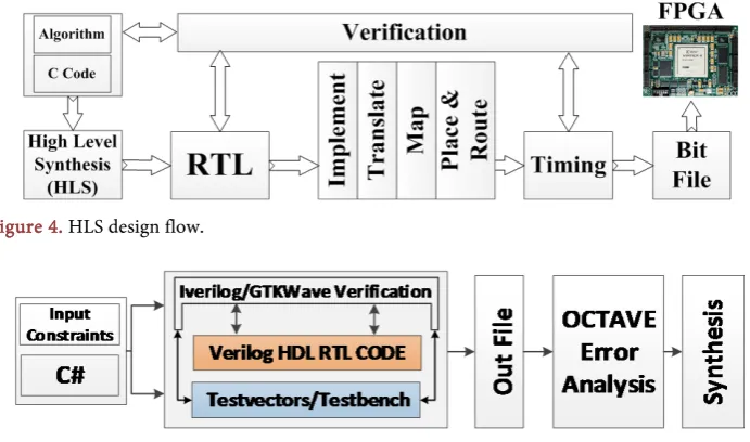
[image:5.595.198.544.491.695.2]The idea behind the fixed-to-floating point conversion system is similar to the High Level Synthesis (HLS) [18] design flow shown in Figure 4. This design flow model is used to create a proposed conversion tool design flow that is shown in Figure 5 below. The conversion tool generates the RTL design files and verifies them using the gener-ated test bench file with user-defined test vectors. All of the test vectors are verified
Figure 4. HLS design flow.
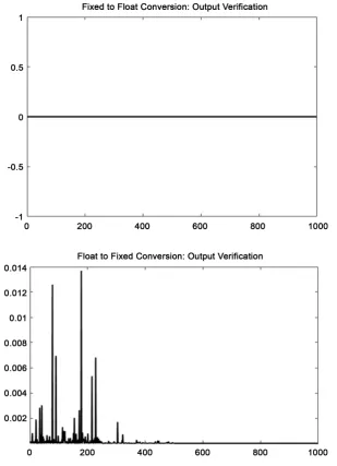
using OCTAVE. If the results are correct and error falls within the acceptable range, synthesis flow will be the next level of operation. Based on user input parameters, the system will create Verilog HDL code, test bench, and verification results by running a batch file. After generating Verilog HDL RTL code and running the desired number of test vectors, the conversion system needs to compare these test vector results from De-sign Under Test (DUT) and expected golden values. The conversion tool generates an OCTAVE file to see the error values. The conversion system can generate any number of test vectors based on the computer hardware, such as CPU speed and memory size. The suggested value can be anywhere between 100 and 1,000,000 test vectors. After running the test bench files using Iverilog, the results are compared using OCTAVE file. The OCTAVE-generated test vector comparisons and error plotting are shown in Fig-ure 6 for fixed-to-float and float-to-fixed verifications.
The main code generating floating and fixed point test vectors and test bench files are shown in Figure 7 and Figure 8, respectively. The float-to-fixed data generation shown in Figure 7 starts by setting a random seed for better random value generation. Four levels of precision are used by the data generator. The first quarter of data values are divided by 2048, followed by 256 and 32. The float value generated within this range is then divided by the maximum value of the unsigned integer to get the floating value. The value is then converted to bytes, ultimately getting a binary string.
The fixed-to-float data generator is exactly the same as the previous one. It uses four precision levels, but instead of using the generated float value, the float value is trans-formed to an integer using 2(Bits−1).
Figure 7. Main code block generating floating point data.
Figure 8. Main code block generating fixed point data.
StaticRandom _seed=newRandom((int)DateTime.Now.Ticks);
//Get a randome number from seed
Random r=newRandom(_seed.Next());
//Code for generating 1st portion of data
floatval= (float)(((double
)r.Next(-Int32.MaxValue/2048,Int32.MaxValue/2048))/(double)Uint32.MaxValue); …..
//Code for generating 2nd portion of data
floatval= (float)(((double)r.Next(-Int32.MaxValue/256,Int32.MaxValue/256)) /
(double)Uint32.MaxValue);
…..
//Code for generating 3rd portion of data
floatval= (float)(((double)r.Next(-Int32.MaxValue/32,Int32.MaxValue/32)) / (double)Int32.MaxValue);
...
//Code for generating 4th portion of data
floatval= (float)(((double)r.Next(-Int32.MaxValue,Int32.MaxValue)) / (double)Int32.MaxValue);
//Convert Values to byte for bit conversion byte[]fbytes=BitConverter.GetBytes(val); BitArray ba=newBitArray(fbytes);
//Convert byte to bit string
stringbitString=ba.ToBitString();
staticRandom _seed=newRandom((int)DateTime.Now.Ticks);
//Get a randome number from seed
Random r=newRandom(_seed.Next());
//Code for generating 1st portion of data
floatval= (float)(((double
)r.Next(-Int32.MaxValue/2048,Int32.MaxValue/2048))/(double)UInt32.MaxValue); ...
//Code for generating 2nd portion of data
floatval= (float)(((double)r.Next(-Int32.MaxValue/256,Int32.MaxValue/256)) /
(double)UInt32.MaxValue);
...
//Code for generating 3rd portion of data
floatval= (float)(((double)r.Next(-Int32.MaxValue/32,Int32.MaxValue/32)) / (double)Int32.MaxValue);
...
//Code for generating 4th portion of data
floatval= (float)(((double)r.Next(-Int32.MaxValue,Int32.MaxValue)) / (double)Int32.MaxValue);
//Convert float value to equivalent integer value longival= (long)(val*Math.Pow(2,(bits-1)));
//Convert Values to byte for bit conversion byte[]fbytes=BitConverter.GetBytes(val); BitArray ba=newBitArray(fbytes);
//Convert byte to bit string
stringbitString=ba.ToBitString();
After reading all the output generated by Icarus Verilog, the code block shown in Figure 9 will read all lines and split them to get input and output values. After that, it will convert the binary to float or fixed using designated functions and also calculate the percent error. The user friendly OCTAVE verification file will be generated as shown in Figure 10. The error plots will be outputted as explained above in Figure 2. The output of the file can be run from MATLAB [19] based on availability.
If the user wants to perform waves-based analysis and verification for certain values, a GTKWave wave window can be used. When the verification code shown in Figure 9 runs and verifies the desired test vectors, it also generates the required vcd file to run in
Figure 9. Verification of float-to-fixed and fixed-to-float.
longtwosComp(stringvalue,intbits)
{
longfxVal=Convert.ToInt64(value,2);
BitArray ba=newBitArray(BitConverter.GetBytes(fxVal));
if(ba[value.Length-1]) {
BitArray baf=newBitArray(64);
for(inti=baf.Count-1;i>=bits;i--)
baf[i] =true;
byte[]longB=newbyte[8];
baf.Or(ba).CopyTo(longB,0);
fxVal=BitConverter.ToInt64(longB,0); }
returnfxVal; }
//Defaut 32bit
floatGetFloatingPointFromBinary(stringbin)
{intfloat2int=Convert.ToInt32(bin,2);
byte[]intBytes=BitConverter.GetBytes(float2int);
returnBitConverter.ToSingle(intBytes,0); }
floatGetFixedPointFromBinary(stringbin,intbits) {
longfxVal=twosComp(bin,bits);
return(float)fxVal/ (float)Math.Pow(2,bits-1); }
floatPercentCalc(doubleinput,doubleoutput) {
return(float)(100*Math.Abs((input-output)/input)); }
//CODEBLOCK: Verification of Fixed-Float conversion
string[]lines=File.ReadAllLines(filePath);
//Get binary values for float and fixed
string[]vals=l.Split(":".ToCharArray());
//Get fixed value from binary string
floatfxValFp=GetFixedPointFromBinary(vals[0],bits);
//Get Float value from binary string
floatfpVal=GetFloatingPointFromBinary(vals[1]);
//Do Percent Calculations
floatpercent=PercentCalc(fxValFp,fpVal);
Figure 10. OCTAVE verification file.
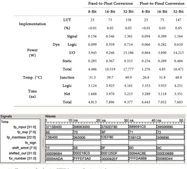
GTKWave. This will allow the user to verify any test vector possible. This could be use-ful for reporting as well as golden test vector verification. The generated vcd files for float-to-fixed and fixed-to-float conversion and their GTKWave wave window are shown in Figure 11 and Figure 12, respectively.
3. Implementation and Results
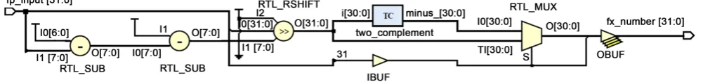
To understand the functionality and effectiveness of the conversion tool, six different blocks are designed, verified and implemented using a Xilinx Virtex 7 FPGA with a 303, 600 available Look Up Table (LUT) [20]. The conversion tool is used to generate Veri-log HDL design and test bench files, and each design is synthesized and implemented using the Xilinx Vivado design suite. The synthesized schematics of 32-bit fixed-to-float and float-to-fixed point are shown in Figure 13 and Figure 14, respectively.
Generated blocks are implemented and area (LUT), power, temperature, and delay are shown in Table 1. Table 1 shows that implementing 8, 16, and 32-bit fixed-to-float and float-to-fixed requires minimal hardware (less than 0.01%, 0.02%, and 0.05% LUT space) with over 100 MHz clock speed for this FPGA. In addition, design and verifica-tion including FPGA implementaverifica-tion of 32-bit fixed-to-float conversion block takes less than three minutes. This created more than 80% time to market (TTM) improve-ment for block generation.
4. Conclusion
A fixed-to-float and float-to-fixed conversion tool is presented for DSP and communi-cation systems. The design tool generates any size fixed-point number to IEEE floating. This design tool generates fixed-to-floating point (32-bit single precision IEEE 754- 1985) as well as floating-to-fixed point conversion design and verification files using user-friendly GUI. The design tool can be used to generate standalone conversion blocks or part of a larger system design and verification. The functional verification of generated blocks is done during the design process to improve TTM and increase productivity. The conversion tool is designed and can be run using open source tools and can be downloaded from the author’s website [21]. Future work will include 64 -bit floating point numbers and user defined fixed point range.
%ForFixedToFloat
load Result_Fixed_to_Float.txt; n=1:size(Result_Fixed_to_Float, 1); ffx=figure;
set(ffx,'Name','Fixed to Float Conversion: Output Verification'); plot(n, Result_Fixed_to_Float(:,3))
title('Fixed to Float Conversion: Output Verification');
fixed_to_float_mismatched=Result_Fixed_to_Float(find(Result_Fixed_to_Float(:,3) ~= 0), 1:2);
%ForFloatToFixed
load Result_Float_to_Fixed.txt; n2=1:size(Result_Float_to_Fixed, 1); ffp=figure;
set(ffp,'Name','Float to Fixed Conversion: Output Verification'); plot(n2, Result_Float_to_Fixed(:,3))
title('Float to Fixed Conversion: Output Verification');
float_to_fixed_mismatched=Result_Float_to_Fixed(find(Result_Float_to_Fixed(:,3) ~= 0), 1:2);
Table 1. Conversion system FPGA implementation.
Fixed-to-Float Conversion Float-to-Fixed Conversion 8-Bit 16-Bit 32-Bit 8-Bit 16-Bit 32-Bit
Implementation LUT 23 73 158 23 75 147 (%) <0.01 0.02 0.05 <0.01 0.03 0.05
Power (W)
Dyn
Signal 0.156 0.546 1.361 0.094 0.389 1.164 Logic 0.099 0.359 0.714 0.066 0.282 0.610 I/O 3.945 9.246 15.186 0.864 3.890 14.213 Static 0.285 0.367 0.515 0.254 0.289 0.484 Total 4.486 10.519 17.777 1.276 4.85 16.471 Temp. (˚C) Junction 31.3 39.7 49.9 26.8 31.8 48.0
Time (ns)
[image:10.595.168.552.92.436.2]Logic 3.124 3.925 4.161 3.353 3.933 4.251 Net 1.688 3.970 5.215 3.289 3.118 3.351 Total 4.813 7.896 9.377 6.643 7.052 7.603
Figure 11. Floating to fixed point GTKWave verification window.
Figure 12. Fixed-to-floating point GTKWave verification window.
[image:10.595.163.557.464.566.2] [image:10.595.45.555.603.680.2]Figure 14. Floating to 32-bit fixed point FPGA schematic.
Acknowledgements
The authors would like to thank Xilinx, Inc. [20] for their valuable support.
References
[1] Yao, F., Li, B. and Zhang, M. (1998) A Fixed-Point DSP Implementation for a Low Bit Rate Vocoder. 1998 5th International Conference on Solid-State and Integrated Circuit Tech-nology, Beijing, 23 October 1998, 365-368.
[2] Bharati, K.S. and Jhunjhunwala, A. (2015) Implementation of Machine Learning Applica-tions on a Fixed-Point DSP. 2015 IEEE 28th Canadian Conference on Electrical and Com-puter Engineering (CCECE),Vancouver, 3-6 May 2015, 1458-1463.
http://dx.doi.org/10.1109/CCECE.2015.7129495
[3] Sun, Z.J. and Liu, X.M. (2008) Application of Floating Point DSP and FPGA in Integration Navigation System. 2008 International Conference on Computer Science and Software En-gineering, 4, 58-61. http://dx.doi.org/10.1109/CCECE.2015.7129495
[4] Langhammer, M. and Pasca, B. (2015) Design and Implementation of an Embedded FPGA Floating Point DSP Block. 2015 IEEE 22nd Symposium on Computer Arithmetic (ARITH), Lyon, 22-24 June 2015, 26-33. http://dx.doi.org/10.1109/ARITH.2015.18
[5] Saldanha, L. and Lysecky, R. (2009) Float-to-Fixed and Fixed-to-Float Hardware Conver-ters for Rapid Hardware/Software Partitioning of Floating Point Software Applications to Static and Dynamic Fixed Point Coprocessors. Design Automation for Embedded Systems, 13, 139-157. http://dx.doi.org/10.1007/s10617-009-9044-4
[6] Duman, E., Can, H. and Akin, E. (2010) FPGA Modules for Conversions between Fixed and Floating-Point in Quartus-II Environment. International Journal of Electronics and Com-puter Science, 10, 120-124.
[7] Wang, X. and Leeser, M. (2010) VFloat: A Variable Precision Fixed- and Floating-Point Li-brary for Reconfigurable Hardware. ACM Transactions on Reconfigurable Technology and Systems, 3, 16:1-16:34. http://dx.doi.org/10.1145/1839480.1839486
[8] Revision of ANSI/IEEE Std 754-1985 (2008) IEEE Standard for Floating-Point Arithmetic. [9] Muller, J.-M., Brisebarre, N., de Dinechin, F., Jeannerod, C.-P., Lefèvre, V., Melquiond, G.,
Revol, N., Stehlé, D. and Torres, S. (2009) Handbook of Floating-Point Arithmetic. 2010 Edition, Birkhäuser, Boston.
[10] Overton, M.L. (2001) Numerical Computing with IEEE Floating Point Arithmetic. SIAM, Philadelphia. http://dx.doi.org/10.1137/1.9780898718072
[11] U.S. National Debt Clock: Real Time. http://www.usdebtclock.org/
[12] Bocchieri, E. (2008) Fixed-Point Arithmetic. In: Automatic Speech Recognition on Mobile Devices and over Communication Networks, Springer, London, 255-275.
http://dx.doi.org/10.1007/978-1-84800-143-5_12
CPMT/SEMI 29th International Electronics Manufacturing Technology Symposium, San Jose, 14-16 July 2004, 140-143. http://dx.doi.org/10.1109/IEMT.2004.1321646
[14] Icarus Verilog. http://iverilog.icarus.com/ [15] GTKWave. http://gtkwave.sourceforge.net/ [16] Octave-Forge. http://octave.sourceforge.net/ [17] Synopsys.com. http://www.synopsys.com/home.aspx
[18] Desmouliers, C., Aslan, S., Oruklu, E., Saniie, J. and Vallina, F.M. (2010) HW/SW Co-De- sign Platform for Image and Video Processing Applications on Virtex-5 FPGA Using PICO. 2010 IEEE International Conference on Electro/Information Technology (EIT), Normal, 20-22 May 2010, 1-6.http://dx.doi.org/10.1109/EIT.2010.5612173
[19] MathWorks—Makers of MATLAB and Simulink. http://www.mathworks.com/ [20] Xilinx. http://www.xilinx.com/
[21] Software Download. http://www.aslanistan.com/Research/Software.html
Submit or recommend next manuscript to SCIRP and we will provide best service for you:
Accepting pre-submission inquiries through Email, Facebook, LinkedIn, Twitter, etc. A wide selection of journals (inclusive of 9 subjects, more than 200 journals)
Providing 24-hour high-quality service User-friendly online submission system Fair and swift peer-review system
Efficient typesetting and proofreading procedure
Display of the result of downloads and visits, as well as the number of cited articles Maximum dissemination of your research work
Submit your manuscript at: http://papersubmission.scirp.org/