A Zeroth-Order Resonance Patch Antenna for Dual Band
Operations with Broad E-plane Beam Widths
Krushna A. Munde
Veeresh G. Kasabegoudar
P. G. Dept., MBES College of Engineering,
Ambajogai, India, 431 517.
P. G. Dept., MBES College of Engineering,
Ambajogai, India, 431 517.
ABSTRACT
In this paper, design of probe fed zeroth order resonance (ZOR) antenna with dual frequency operation is presented. The mushroom structure is placed at the center of the geometry and the grounded via to have the desired ZOR response. The feed is connected between the inner ring and the mushroom structure. There are several ZOR antennas are available in literature with only one resonant frequency. However, in this work we presented ZOR antenna which excites dual resonances. The second resonance is obtained by placing two stubs and an outer ring. Also, it may be noted that we get nearly broader E-plane beamwidths (112 and 90 degrees) at both the resonance frequencies. The bandwidth of 7.8% at second resonant frequency was obtained as compared to the conventional patch antennas (2~3%). At first resonance only narrow band performance was observed. Measured results fairly agree with the simulated data.
Keywords
― Half power beam width (HPBW), Hybrid, Zeroth-order resonance (ZOR) mode, Metamaterials.1. INTRODUCTION
In trans-receivers, planar antennas play a very important role in the field of wireless communications. Some of them are microstrip patch antennas, slot antennas, and folded dipole antennas with each type having their own properties and usage. But, the microstrip patch antennas have been the most popular antennas in modern wireless communication systems as they have several desirable attributes, such as a low-profile planar configuration, a light weight, a simple design principle, and a low fabrication cost [1-2]. However, the serious problem of patch antennas is their narrow bandwidth due to surface wave losses and large size of patch for better performance and also narrow scanning range. This weakness has created a need for an antenna with an enhanced beamwidth and small in size. To realize a broad beamwidth, many antennas using the various techniques have been reported. For example, by using the phase array patch structures [3], the multilayered structures [4-6] or the parasitic radiators [7-8], it is possible to design the patch antennas with a broad beamwidth. However, they have several limitations such as a larger size, a difficult design, and a multi-layered structure. These characteristics can be achieved using ZOR antennas. For example, the antennas utilize the zeroth-order resonance (ZOR) mode of the mushroom structure and the TM010 modes of the conventional rectangular patch are
presented in [9-10]. The detailed theory on ZOR can be found in [11-17].
In this work, dual frequency ZOR antenna is presented. The antenna presented in this work is taken from [12]. However, the antenna presented in [12] offers resonance only at one frequency. The antenna presented here is similar to [12] with an additional ring and two stubs to have second resonance. Also, by modifying the stub positions dual band characteristics can be obtained. The antenna is simulated using Ansoft’s High Frequency Structure Simulator (HFSS) v.13 [18]. More details on this geometry are discussed in subsequent sections. Section 2 presents the geometry structure of the proposed antenna. Design and optimization procedure of the proposed antenna is presented in Section 3. Section 4 presents the validation of the fabricated prototype and discussions on the measured results are also presented there. Finally, conclusions of this study are presented in Section 5.
2. ANTENNA GEOMETRY
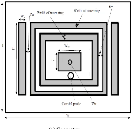
Figure 1(a) shows the basic geometry of proposed dual frequency ZOR patch antenna. Substrate used for the design is a glass epoxy (FR 4) with thickness of 3.175mm, dielectric constant of 4.4, and a loss tangent equal to 0.01. The detailed optimization procedure of the proposed antenna and its optimum dimensions, and characteristics are presented in Section 3. All parameters of the geometry are indicated in Figure 1(a).
[image:1.595.322.541.487.702.2]Wg
[image:2.595.59.278.68.254.2](b) Simulation setup
Figure 1: Geometry of proposed dual frequency ZOR patch antenna.
3. GEOMETRY OPTIMIZATION AND
DISCUSSIONS
In this section parametric study is conducted to optimize the proposed antenna. The key design parameters used for the optimization are length of the stub, width of the stub, gap between stub and outer ring, and inner ring size. The detailed analysis of these parameters is investigated in the following subsections. All simulations were carried out with HFSS software (pl. ref. its setup in Figure 1(b)) which is a Finite Difference Time Domain (FDTD) based electromagnetic (EM) software.
3.1 Effect of Stub
3.1.1 Effect of Length
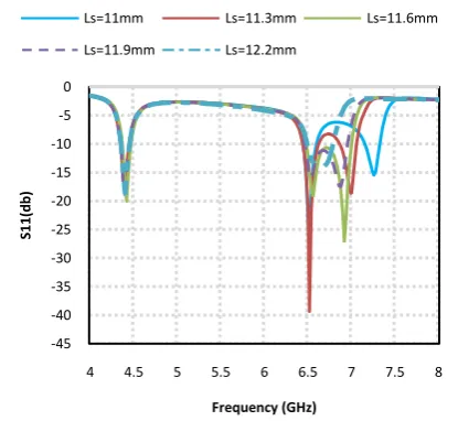
[image:2.595.326.534.77.268.2]Two stubs are showed in Figure 1(a). The lengths of these two stubs are changed from 11mm to 12.2mm in steps of 0.3mm keeping all the parameters constant. Return loss characteristics of these changes are given in Figure 6 and its effects are presented in Table 1. From this study it can be noted that the second resonance is shifted towards right as the value of length changes with first resonance unchanged.
Table 1: Resonant frequency deviation due to variation in the length of stub (Slot hole kept constant)
Length of stub
(mm) 11 11.3 11.6 11.9 12.2
First Resonant Frequency(fr1)
(GHz)
4.42 4.42 4.42 4.42 4.42
Second Resonant Frequency(fr2)
(GHz)
7.28
7 6.92 6.88 6.7
Figure 2: Return loss vs. frequency plot for variation in length of stub.
3.1.2 Effect of Width
In this the width of stubs changes from 1mm to 1.8mm in steps of 0.2mm keeping all other parameters constant. Return loss characteristics of these changes given in Figure 3 and its data values are presented in Table 2. From this study it is observed that the second resonance is shifted towards left as the value of width changes with keeping first resonance unaltered.
Figure 3: Return loss vs. frequency plot for variation in width of stub.
Table 2: Resonant frequency deviation due to variation in the width of stubs (Inner ring kept constant)
Width of stub (mm)
1 1.2 1.4 1.6 1.8
First Resonant
Frequency(fr1) (GHz) 4.42 4.42 4.42 4.42 4.42
Second Resonant
Frequency(fr2) (GHz) 7.04 6.94 6.92 6.88 6.78
-45 -40 -35 -30 -25 -20 -15 -10 -5 0
4 4.5 5 5.5 6 6.5 7 7.5 8
S1
1
(d
b)
Frequency (GHz)
Ls=11mm Ls=11.3mm Ls=11.6mm
Ls=11.9mm Ls=12.2mm
-40 -35 -30 -25 -20 -15 -10 -5 0
4 4.5 5 5.5 6 6.5 7 7.5 8
S11(db)
Frequency (GHz)
Ws=1mm Ws=1.2mm Ws=1.4mm
[image:2.595.325.527.410.594.2]3.1.3 Effect of Gap
In another effort gap between the stubs and an outer ring changed from 0.1mm to 0.5mm in steps of 0.1mm with other parameters are kept constant. Return loss characteristics of these changes given in Figure 8. From Table 3 it can be noticed that the second resonance is shifted towards left as the value of gap between stubs and outer ring changes. As explained in earlier paragraphs, here also the first resonant frequency remains constant.
Figure 4: Return loss vs. frequency plot for variation in gap between outer ring and stub.
Table 3: Resonant frequency deviation due to variation in the gap of stubs (Inner ring kept constant)
Gap between stubs and outer ring (mm)
0.1 0.2 0.3 0.4 0.5
First Resonant Frequency(fr1)
(GHz)
4.42 4.42 4.42 4.42 4.42
Second Resonant Frequency(fr2)
(GHz)
6.92 6.8 6.76 6.7 6.68
3.2 Effect of Inner Ring
The width of inner ring is changed from 2mm to 3mm in steps of 0.2mm with all other parameters kept constant. Return loss characteristics of this study are presented in Figure 5. From Table 4 it is observed that the first resonance frequency changes with respect to the inner ring width, keeping the second resonance frequency unaltered.
Table 4: Resonant frequency deviation due to inner ring (outer ring width = 0.5mm constant).
Inner ring(mm) 2 2.2 2.4 2.6 2.8 3.0
First resonant frequency(fr1)
(GHz)
4.42 4.38 4.3 4.28 4.24 4.20
Second resonant frequency(fr2)
(GHz)
6.92 6.92 6.92 6.92 6.92 6.92
[image:3.595.326.538.106.272.2]Optimized parameters of the proposed geometry are listed in Table 5.
Figure 5: Return loss vs. frequency plot for variation in width of inner ring.
Table 5: Optimized parameters of geometry shown in Figure 1.
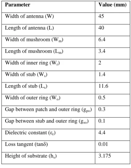
Parameter Value (mm)
Width of antenna (W) 45
Length of antenna (L) 40
Width of mushroom (Wm) 6.4
Length of mushroom (Lm) 3.4
Width of inner ring (Wr) 2
Width of stub (Ws) 1.4
Length of stub (Ls) 11.6
Width of outer ring (Wo) 0.5
Gap between patch and outer ring (gpo) 0.3
Gap between stub and outer ring (gso) 0.1
Dielectric constant (εr) 4.4
Loss tangent (tanδ) 0.01
Height of substrate (hs) 3.175
4.
EXPERIMENTAL VALIDATION OF
THE GEOMETRY AND DISCUSSIONS
The geometry shown in Figure 1 with its optimized Dimensions presented in Table 5 was fabricated and tested. The substrate used for the fabrication is the FR 4 glass epoxy with dielectric constant of 4.4, loss tangent (tan (δ)) = 0.01, and thickness of 3.175mm. A photograph of the fabricated prototype is shown in Figure 6(a) and its S11 measurement
setup is shown in Figure 6(b). Return loss characteristics of measured and simulated values are compared in Figure 7. The measured results fairly agree with the simulated values.
-30 -25 -20 -15 -10 -5 0
4 4.5 5 5.5 6 6.5 7 7.5 8
S1
1
(d
b)
Frequency (GHz)
gso=0.1mm gso=0.2mm gso=0.3mm
gso=0.4mm gso=0.5mm
-35 -30 -25 -20 -15 -10 -5 0
4 4.5 5 5.5 6 6.5 7 7.5 8
S1
1
(d
b)
Frequency (GHz)
Wr=2mm Wr=2.2mm Wr=2.4mm
[image:3.595.62.277.178.357.2] [image:3.595.322.534.342.612.2]From Figure 7 it may be noted that the proposed antenna is having the dual operating frequencies 4.42GHz and 6.92GHz and are similar to the simulated values. The simulated and measured -10 dB bandwidths are 7.28% and 6.27% respectively for second resonance. However, it may be noted that at first resonance no bandwidth was observed. Radiation patterns of the antenna at various frequencies are given in Figure 8. From these patterns it is clear that a broad E-plane beamwidths can be obtained at the frequencies of interest.
(a) Fabricated prototype
[image:4.595.333.527.75.211.2](b) S11 measurement setup
[image:4.595.66.268.170.312.2]Figure 6: Photographs of the fabricated antenna and its measurement Setup.
Figure 7: Return loss characteristic plot of the proposed antenna shown in Figure 1.
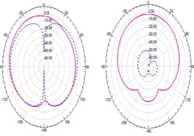
(a) E-plane and H-plane patterns at 4.42GHz
(b) E-plane and H-plane patterns at 6.56GHz
[image:4.595.70.264.342.493.2](c) E-plane and H-plane patterns at 6.92GHz
Figure 8: E and H plane radiation pattern at different frequencies in operating band (Left side: E-plane patterns; Right side: H-plane patterns; Solid lines:
co-poln.; Dashed lines: cross poln.).
5. CONCLUSIONS
[image:4.595.63.272.519.724.2]The overall ratio of resonant frequency (fr2/fr1) can be
changed from 1.50 to 1.64. Hence the proposed antenna is suitable for application where the broad E-plane beamwidths are required. The further work includes bandwidth enhancement of the proposed antenna keeping the beamwidth unaltered. Also, modeling of the antenna has to be carried out to better understand the working of proposed antenna.
6. REFERENCES
[1] R. Garg, P. Bhartia, I. Bahl, and A. Ittipiboon, Microstrip Antenna Design Handbook. Boston, MA: Artech House, 2000.
[2] C. A. Balanis, Antenna Theory: Analysis and Design, 3rd Edn. New York Wiley, 2005.
[3] T. P. Wong and K. M. Luk, “A wideband L-probe patch antenna array with wide beamwidth,” IEEE Trans. Antennas Propag., vol. 51, no. 10, pp. 3012–3014, 2003.
[4] C. W. Su, S. K. Huang, and C. H. Lee, “CP microstrip antenna with wide beamwidth for GPS band application,” Electron. Lett., vol. 43, no. 20, Sep. 2007. [5] X. L. Bao and M. J. Ammann, “Dual-frequency dual
circularly-polarized patch antenna with wide beamwidth,” Electron. Lett., vol. 44, no. 21, pp. 1233– 1234, 2008.
[6] Z.-S. Duan, S.-B. Qu, Y. Wu, and J.-Q. Zhang, “Wide bandwidth and broad beamwidth microstrip patch antenna,” Electron. Lett., vol. 45, no. 5, pp. 249–250, Feb. 2009.
[7] S.-W.Qu, J.-L. Li, andQ.Xue, “Bowtie dipole antenna with wide beamwidth for base station application,” IEEE Antennas Wireless Propag. Lett., vol. 6, pp. 293– 295, 2007.
[8] Z. N. Chen,W. K. Toh, and X. M. Qing, “A microstrip patch antenna with broadened beamwidth,” Microw. Opt. Technol. Lett., vol. 50, no. 7, pp. 1885–1888, Jul. 2008.
[9] A. Sanada, C. Caloz, and T. Itoh, “Planar distributed structures with negative refractive properties,” IEEE Trans. Microwave Theory Tech., vol. 52, no. 4, pp. 1252–1263, Apr. 2004.
[10] A. Lai, C. Caloz, and T. Itoh, “Composite right/left-handed transmission line metamaterials,” IEEE Microwave Mag., vol. 5, no. 3, pp. 34–50, Sep. 2004. [11] A. Sanada, C. Caloz, and T. Itoh, “Zeroth order
resonance in composite right/left-handed transmission line resonators,” in Proc. Asia-Pacific Microwave Conf., Seoul, Korea, vol. 3, pp. 1588–1592 2003. [12] Seung-Tae Ko and Jeong-Hae Lee, “Hybrid
Zeroth-Order Resonance Patch Antenna With Broad E-Plane Beamwidth,” IEEE Transactions on Antennas and Propagation, Vol. 61, No. 1, January 2013
[13] C. Caloz and T. Itoh, Electromagnatic Metamaterials (Transmission Line theory and microwave application), Wiley IEEE Press 1st edition, 2005.
[14] J. G. Lee and J. H. Lee, “Zeroth order resonance loop antenna,” IEEE Trans. Antennas Propag., vol. 55, no. 3, pp. 994–997, Mar. 2007.
[15] R.W. Ziolkowski and A. Kipple, “Application of double negative metamaterials to increase the power radiated by electrically small antennas,” IEEE Trans. Antennas Propag., vol.51, pp. 2626–2640, Oct. 2003.
[16] R. Das Saswato, "Metamaterials Arrive in Cell phones" (Online magazine article). Metamterial antennas. IEEE Spectrum. 2011-03-09.
[17] G. K. Singh, R. K. Chaudhary*, and K. V. Srivastava, “A compact zeroth order resonating antenna using complementary split ring resonator with mushroom type of structure,” Progress In Electromagnetics Research Letters, Vol. 28, 139-148, 2012.