International Journal of Emerging Technology and Advanced Engineering
Website: www.ijetae.com (ISSN 2250-2459, ISO 9001:2008 Certified Journal, Volume 7, Issue 11, November 2017)
332
On the Petri Nets Control of the Multicellular Converter
Philippe Djondiné
1, Jean-Pierre Barbot
2, Malek Ghanes
31Department of Physics, Faculty of Science, The University of Ngaoundéré, P.O. Box 454, Ngaoundéré, Cameroon 1,2,3
ECS-Lab, EA3649, ENSEA, Cergy Cedex, Cergy-Pontoise 95014, France, Laboratoire QUARTZ EA 7393
Abstract— The serial multicellular structure of static
converters is widely used for high power applications. However, some controls of these converters are unreliable and are sensitive to fluctuations in some of its parameters. In this article is proposed a control by Petri nets that has overcome these deficiencies by making the converter robust vis-à-vis fluctuations that can affect the load or the input voltage. This has been successfully tested by digital simulation in the case of a two-cell converter connected to a non-strictly dissipative non-linear load.
Keywords— Petri nets control, robustness, multicellular
converter, hybrid dynamic systems.
I. INTRODUCTION
The power electronics knows important technological developments. This is carried out thanks to the developments of the semiconductor of power components but also of new systems of energy conversion. Among these systems, multicellular converters are based on the association in series of the elementary cells of commutation. This structure appeared at the beginning of the 90’s [1], makes it possible to share the constraints in tension and/or while running in high voltages installations by the cells of commutation series-connected and also to improve the harmonic contents of the forms of waves.
Several patents have been filed on this subject [2]. This new topology is becoming more and more attractive in industrial applications. Indeed, this multicellular structure is an interesting system for high power applications. To benefit as well as possible from the large potential of the multicellular structure, various studies have been developed in the literature. Further, the normal operation of the p-cell conversion series is obtained when the voltages are multiples of E/p, where E is the source voltage and p is the number of cells. This structure divides the voltage by distributing it over several cells in series, improves the spectral quality of the cut voltage and reduces the ripples of the voltage [3]. Several models, of this type of converter, are used for the development of open-loop [4] and closed-loop control laws [5]. Nevertheless, the current control algorithms do not take into account its hybrid character. In this article, our goal is to design and test a Petri nets control, based on an instantaneous model describing the hybrid behavior of the multicell converter.
After describing a model of the multicell converter in section 2, section 3 presents the Petri net control strategy. The implementation of the proposed control for simulation for the case of a two-cell converter connected to a non-strictly dissipative nonlinear load is described in section 4.
II. MULTICELLULAR CONVERTER MODEL
Throughout the paper, the p-cell converter connects in series p elementary cells and a passive load R and L as illustrated in figure 1. Each switching cell is controlled by a binary input signal ( ) for . This signal ( ) is equal to 1 when the upper switch of the cell is conducting and 0 when the lower complementary switch of the cell is conducting. In order to ensure that, we must determine the floating capacitor voltages:
( )
where
From equation. (1), for , we have:
⇒ ( )
Increasing , we find the general expression for the capacitor voltages:
( )
In order to determine the converter model, we consider two adjacent cells: and connected with the capacitor (Figure 1). The capacitor voltage is determined by the evolution of the capacitor current. This, in turn, is given by the configuration of the switches:
( ) ( )
Where if the upper switch in is conducting and if the lower switch in is conducting. The capacitor voltage is then given by equation (5):
⇒
International Journal of Emerging Technology and Advanced Engineering
Website: www.ijetae.com (ISSN 2250-2459, ISO 9001:2008 Certified Journal, Volume 7, Issue 11, November 2017)
333
Equation (5) can be generalized for all capacitors. Next we determine the output voltage as the sum of all cell voltages:
∑
∑( ) ( )
From equation (6), we note that we can have multiple voltage levels at the output, depending on the configuration of the switches. For a converter with cells, we have
voltage levels: ( ) . This means that the
voltage jumps at the output are smaller than the ones in classical structures. For the multicell converter with an load in figure 1, the output current is given by:
( )
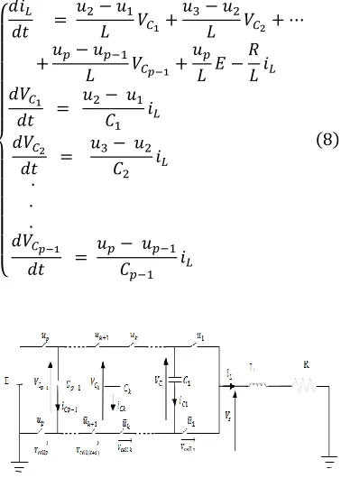
From equations (5), (6) and (7) we get the instantaneous model of the multicell converter in figure 2:
{
[image:2.612.75.264.374.644.2]
( )
Figure 1: A p cells converter connected to RL load
where is the flying capacitor voltage and is the output load current, which is the only measurable output. for ; are the capacitors, E is the voltage of the source, R is the resistance and L is the inductance.
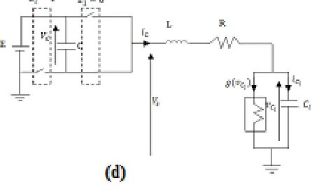
To simplify the study and the notations, we will study the overlapping operation of a converter with 2 cells (Figure 2). Its function is to supply a passive load ( ) in series with another nonlinear load connected in parallel with a capacitor [6]. Four operating modes are then possible as shown in figure 3. Note that the floating source takes part in the evolution of the dynamics of the system only to the third and fourth mode. In the third mode, the capacity discharges and charge during the fourth mode. Thus, if these two modes last same time with a constant charging current, then the average power transmitted by this floating source over one period of commutation is null. We also notice that these two modes make it possible to
obtain by commutation the additional level on the output voltage .
Figure 2: Two– cells chopper connected to a nonlinear load
[image:2.612.344.541.387.512.2]International Journal of Emerging Technology and Advanced Engineering
Website: www.ijetae.com (ISSN 2250-2459, ISO 9001:2008 Certified Journal, Volume 7, Issue 11, November 2017)
[image:3.612.333.556.151.290.2]334
Figure 3: Switching cell and its configurations.
The system model can be represented by three differential equations giving its state space.
{
( )
( )
( ) ( )
where ( ) is a piecewise – linear function
( ) ( ) (| | | |) ( )
which is the mathematical representation of the characteristic curve of nonlinear load. The slopes of the inner and outer regions are and , while indicates break points.
III. HYBRID CONTROL OF SERIAL MULTICELLULAR
CONVERTER BASED ON PETRI NETS
International Journal of Emerging Technology and Advanced Engineering
Website: www.ijetae.com (ISSN 2250-2459, ISO 9001:2008 Certified Journal, Volume 7, Issue 11, November 2017)
335
They are often modeled by differential equations or transfer functions. For discrete dynamical systems, the state space is a discrete set of Boolean value [7]. Systems including both continuous and discrete state are called hybrid dynamic systems (HDS). In a very simplified one HDS has two sub sets, a continuous block and a discrete block:
The continuous block is the dynamic evolution of the state continues, in our case the RL connection.
[image:4.612.319.564.318.579.2] The block has the discrete system is discrete event receives internal events, external conditions In this work, we were interested in modeling method and control systems hybrid event-based dominant the use of Petri nets [8]. The method is illustrated in Figure 4
Figure 4: Global structure of the Petri net control
The control consists of two parts, a continuous and a discrete. The first is based on a classical PI control loop for regulating the output voltage. This loop has as input the error and as output a current. The
second control loop is done by a Petri net whose mission is the current regulation to value calculated by the PI. The current regulation is followed by a voltage balancing to ensure a better distribution of the latter in each cell. For the current regulation, a hysteresis methodology is used. An operating band, , is provided, such that the output current, , rests inside ( ). Figure 5 represents the Petri net control of the switches, the places and respectively are modeling the state of the switches of cells Cell1, and Cell2. This algorithm is developed in order to control the system, in case it has an imbalance in the voltage of cells. The transition from one place to another is dependent on the voltage state (Table 2), current and chopper configurations. The closure of the
switch of the cell ( ) depends on the validation of the transition and the elapsed delay . This delay models the time allowed between two successive commutations, it is based on the technology used for making the switch. For our work we took the same delay ie .
In the Petri the role of two arcs inhibitors, is to prevent the presence of more than one, token in places and .
Figure 5: Petri net control switches of the converter
TABLE I: Signification of places
Places Designations
P0 Initial state
P1 The switch of the first cell
P2 The switch of the second cell
TABLE III: The transitions
Transitions Designations
t01 (e ≥ +δ) ou ((-δ < e < +δ) et (VC > E/2))
t02 (e ≥ +δ) ou ((-δ < e < +δ) et (VC < E/2))
t10 (e ≤ -δ) ou ((-δ < e < +δ) et (VC < E/2))
t20 (e ≤ -δ) ou ((-δ <e < +δ) et (VC > E/2))
The significance of all places and transition is shown in
TABLE III and TABLE IV
IV. SIMULATIONS RESULTS
In this section the simulation results will be presented in order to show the behavior of the proposed control. The simulation parameters are the following:
- voltage source :
- capacitances : 𝜇𝐹 𝜇𝐹
[image:4.612.55.282.324.429.2]International Journal of Emerging Technology and Advanced Engineering
Website: www.ijetae.com (ISSN 2250-2459, ISO 9001:2008 Certified Journal, Volume 7, Issue 11, November 2017)
336
- 𝑚
- 𝛺
Figure 6 and 7 respectively show the evolutions of the floating voltages and the evolution of the current in the load . We observe that the floating voltage reaches their reference and that the current in the load remains equal to the desired value . The error is greatly attenuated with a
low rate of current ripple in the load, of the order of 0.5%. The major advantage of this command is its range of validity. Indeed, it has shown its effectiveness for different reference values . Figure 6 and 7 show that the
[image:5.612.67.268.313.458.2]proposed control strategy is effective and leads to satisfactory results and consistent objectives.
Figure 6 : Hybrid control based on Petri net
Figure 7: Hybrid control based on Petri net
V. CONCLUSION
In this paper a direct Petri nets control algorithm applied to a flying capacitor converter has been presented and developed. Petri nets are among the powerful tools for modeling and control of such systems which have discontinuities in their mathematical models. The proposed algorithm is based on the statements of floating capacitor, the current reference calculated by the PI and the authorized configurations. Finally simulation results show the convergence of the load current to a neighborhood of the value of the nominal operating current response times over. Furthermore an optimal steady-state trajectory is obtained according to the adjacency rules of the power switches. The simulation results affirm a good performance of the proposed Petri nets control.
REFERENCES
[1] T. A. Meynard and H. Foch. Brevet français No. 91.09582 du 25 juillet 91, dépôt International PCT (Europe, Japon, USA, Canada) No. 92/00652 du 8 Juillet 92, 1991.
[2] T. A. Meynard and H. Foch ―Electronic device for electrical energy conversion between a voltage source and a current source by means of controllable switching cells‖, European Patent, 92/916336.8, 1992 [3] S. Ben Said, K. Ben Saad and M. Benrejeb. ―On a PI control of a multicellular converter‖. International Conference on Control, Engineering and Information Technology, 07-09 Juin Sousse 2013. [4] O. Tachon, M. Fadel and T. Meynard. ‖Control of series multicell
converters by linear state feedback decoupling‖ EPF Grenoble, pp. 1588-1593, 1997.
[5] O. Bethoux, J-P. Barbot. ―Multi-cell chopper direct control law preserving optimal limit cycles‖. In IEEE CCA, 2002.
[6] P. Djondiné, M. Ghanes, J-P. Barbot and B. Essimbi. ―Dynamical behaviors of multicellular chopper‖. Journal of Control Science and Engineering, 2(1), 35–42, 2014
[7] R. Goebel, J. Hespanha, A-R. Teel, C. Cai, and R. Sanfelice. ―Hybrid systems: generalized solutions and robust stability‖ .Proceedings of IFAC, Nolcos, 2004
[8] S. Lafortune, G. Cassandra. ―Introduction to discrete event systems‖ Published in september 1999 by Kuwer Academic Publishers, 848 pages. Hardbound
[9] O. Bethoux, J. Barbot, ―Commande permettant le contrôle du convertisseur multicellulaire série à nombre non premier de cellules‖. Revue science et technique de l’automatique. Vol 4, n°1 pp 44-49, 2007.
[10] M. Fadel and T. A. Meynard. ―Equilibrage des tensions dans les convertisseurs statiques multicellulaires série: Modélisation‖. EPF Grenoble, pp. 115-120, 1996.
2.5 2.6 2.7 2.8 2.9 3 x 10⁻³ -20
-10 0 10 20 30 40 50 60 70 80
temps(s)
V
c(
V
)
0 0.02 0.04 0.06 0.08 0.1 0.12 0.14 0.16 0.18 0.2 0
0.5 1 1.5 2 2.5 3 3.5 4 4.5
temps(s)
[image:5.612.75.265.489.632.2]