© 2016, IRJET | Impact Factor value: 4.45 | ISO 9001:2008 Certified Journal
| Page 1305
Rectangular DGS Loaded Circular Microstrip Patch Antenna for
Wireless Applications
Sayali J. Pawar
1, Mandar P. Joshi
21
M. E Student, Dept. of Electronics & Telecommunication, Gokhale Education Society’s R. H. Sapat College Of
Engineering, Management Studies and Research, Nashik, Maharashtra, India
2
Asst. Professor, Dept. of Electronics & Telecommunication, Gokhale Education Society’s R.H.Sapat College Of
Engineering, Management Studies and Research, Nashik, Maharashtra, India
---***---Abstract -
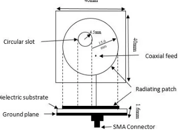
A compact dual-band Coaxial feed circularMicrostrip patch antenna (CMPA) is presented and discussed for ISM(2.4-2.5GHz) and WLAN(5.150-5.350GHz) band applications. The proposed antenna is designed on a FR4 substrate with dielectric constant of 4.4 and an overall size of 40 × 40 × 1.6 . Dual frequency bands are obtained by inserting a circular slot in the circular radiator as well as bandwidth enhancement is obtained by loading a rectangular shaped defected ground structure. The proposed antenna achieves < -10dB. Maximum
bandwidth observed is about 68MHz for ISM band and 174MHz for WLAN band. The antenna simulated using CAD FEKO simulation software.
Key Words: dual band; microstrip; circular; rectangular; DGS
1.INTRODUCTION
The rapid advancement in microwave and wireless communication has attracted the interests in microstrip antennas. With the wide spread proliferation of wireless communication technology in recent years, the demand for compact, low profile, ease of compatibility with microwave circuits and less cost has increased significantly [17].
However, in spite of these advantages microstrip antennas suffers from limitations such as narrow bandwidth and low gain. To avoid use of two separate antennas for two frequency bands and to fulfil the demand of leading market there is a need to develop the dual band antennas. Many designs are reported in literature, for different communication bands, which uses different techniques such as slotting, defected ground structure etc. to enhance the performance of Microstrip patch antennas also varieties of patch structures are designed. Now a days defected ground structure (DGS) microstrip patch antennas have been rapidly developed for multi-band and broad band in wideband communication systems. M.Haroon Taria et.al proposed that the requirement of high speed wireless local area networks (IEEE 802.11a standard) and other communication systems.Bandwidth
increases due to larger width of microstrip antenna.[7]. In past few years, investigators have been studied different methods to enhance the bandwidth. It is observed that efficiency of antenna get increases by increasing bandwidth and gain decreases accordingly. J.A. Ansari et.al
described that substrate thickness and slots length have significant effect on frequency ratio [11]. Garima et.al
proposed that by increasing the size of diamond shaped slot effective radius of circle get decreases and patch current increases. So that, impedance bandwidth and gain of antenna get increases. Improved bandwidth is of 13.58% for C-band application [12]. C. J. Wang et.al
presented that a Z-like slot get loaded on a patch which increases resonant frequency as number of slots increases without increasing occupied slot area [14]. Srijita Chakraborty et.al observed that by modifying zigzag shaped DGS, antenna resonate at Bluetooth, WiMAX and IMT bands respectively [17]. A.K.Arya et.al proposed different defected ground structures in detail. It has been observed that from single Skew-F shaped defect in ground plane,the frequency ratio is decreases by increasing the length of middle arm of F. It has been observed that good impedance matching is achieved by increasing the number of slots [18]. U. Chakraborty et.al described that a dual band microstrip patch antenna for WLAN application is responsible to shift down the resonant frequency to lower values. Slot impedance is directly proportional to length of the slot is gradually increased [19].
© 2016, IRJET | Impact Factor value: 4.45 | ISO 9001:2008 Certified Journal
| Page 1306
2.ANTENNA DESIGN
Dual band CMPA is designed for ISM and WLAN band applications. Proposed antenna is simulated by FR-4 dielectric substrate with 1.6mm thickness which has permittivity and loss tangent of 4.4 and 0.02 respectively. 40 × 40 ground area is designed. Coaxial feeding is used for designing dual band circular microstrip patch antenna at x=4mm and y=4mm with radius of circular patch, α is 15. 6mm.Circular slot with radius 4.5mm is designed. Bandwidth enhancement of designed dual band CMPA get enhanced using rectangular shaped Defected Ground Structure(DGS).
2.1Dual Band CMPA Without DGS
[image:2.595.324.449.207.278.2]The geometry of dual band CMPA without DGS is shown in fig.1.
Fig -1: Dual band CMPA without DGS
Radius of Circular patch(α) is given in equation (1),
α=
(1)
Where,
F =
√
α= Radius of circular patch
h= Height of dielectric substrate
=Relative permittivity of substrate
Here, /16 is used to design circular slot.
2.2 Dual Band CMPA With DGS
2.2.1 Dual Band CMPA With Rectangular DGS
Front view of dual band CMPA with rectangular shaped DGS is same as for dual band CMPA without DGS. Back view of dual band CMPA with rectangular DGS is shown in fig.2. For rectangular DGS length is 8mm and width is 4mm, which is placed at x= 0mm and y= 15mm on the ground plane. The dimensions of rectangular DGS are taken according to /8 and /16, where λg is guided wavelength.
Fig -2: Dual band CMPA with Rectangular DGS
3.ANTENNA ANALYSIS
Performance of circular shaped dual band MPA depends on number of factors such as height of substrate, feeding point, radius of circular slot and circular patch. Also antenna performance depends upon shape, size of ground plane and position of DGS.
For designing dual band CMPA, resonant frequencies are not adequate due to increasing the size of circular slot. Therefore, it is required to maintain the size of circular slot 4. 5mm. However, it is observed that, if size of circular slot increases resonance frequency shifts towards higher mode. Hence, optimum value of radius for designing circular slot is taken as 4.5mm as shown in fig.1. The feed point is optimized and selected location is in between center and edge of the patch. Therefore, optimum value of feed point for proposed antenna is at x=4mm and y=4mm as shown in fig.1. Similarly, for rectangular slotted ground plane the length and width of slot is optimized and taken as 8mm and 4mm respectively.
4.RESULTS AND DISCUSION
4.1Dual Band CMPA Without DGS
[image:2.595.58.239.345.477.2]© 2016, IRJET | Impact Factor value: 4.45 | ISO 9001:2008 Certified Journal
| Page 1307
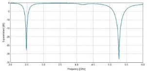
Fig-3: Return loss for dual band CMPA without DGS
Voltage standing wave ratio (VSWR)of antenna at resonating frequency is shown in fig.4.
Fig -4: VSWR for dual band CMPA without DGS
The observed value of VSWR at 2.48GHz is 1.24 and at 5.32GHz is 1.21 which shows that a good impedance matching is achieved by dual band CMPA without DGS.
[image:3.595.251.555.49.297.2]Maximum current at resonating frequencies 2.48GHz and 5.32GHz is observed on the circular radiating patch. Current distribution is shown in fig.5. Surface current at 2.48GHz is 54 dB A/m shows that the more patch current directed in particular direction which forms a constructive pattern to resonate a proposed antenna with less return loss and more radiation for ISM band and at 5.32GHz large current that is 45 dB A/m concentrated from circumference towards center on the radiator which gives good performance for WLAN band.
Fig -5: Current Distribution(a)at 2.48GHz (b)at 5.32Hz for dual band CMPA without DGS
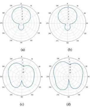
Radiation patterns without DGS for 2.48GHz and 5.32GHz resonating frequencies is shown in fig.6.
Fig -6: Radiation patterns at 2.48GHz are (a), (b) and at 5.32GHz are (c), (d) for dual band CMPA without DGS
From Simulated radiation pattern it has been observed that at 2.48GHz maximum gain that is 2.18dBi and at 5.32GHz is 0.55dBi.
4.2 Dual Band CMPA with DGS
4.2.1 Dual Band CMPA with Rectangular DGS
[image:3.595.38.211.235.320.2]As shown in fig. 3, narrow bandwidth is obtained for dual band antenna. Hence to enhance the bandwidth rectangular shaped slot is inserted in the ground plane. Return loss for dual band circular microstrip patch antenna with rectangular DGS is represented in fig.7.It shows that proposed antenna resonates at resonating frequencies of 2.42GHz and 5.27GHz with return loss of -28.97dB and -33.46dB respectively. After inserting a rectangular DGS, observed bandwidth of lower band is 68MHz and of higher band is 174MHz. Which produces large current distribution all over the patch to radiate CMPA with rectangular DGS.
Fig -7: Return loss for dual band CMPA with rectangular DGS
[image:3.595.45.200.533.617.2] [image:3.595.321.472.579.652.2]© 2016, IRJET | Impact Factor value: 4.45 | ISO 9001:2008 Certified Journal
| Page 1308
Fig -8: VSWR for dual band CMPA with rectangular DGS
The circular radiating patch having maximum uniform current distribution at resonating frequencies 2.48GHz and 5. 27GHz.Current distribution is shown in fig.9. Surface current at 2.48GHz is 45 dB A/m and at 5.27GHz is 36 dB A/m.
Fig -9: Current Distribution(a)at 2.42GHz (b)5.27GHz for dual band CMPA with rectangular DGS
Radiation patterns with DGS for 2.42GHz and 5.27GHz resonating frequencies is shown in fig.10.
Fig -10: Radiation patterns at 2.42GHz are (a),(b) and at 5.27GHz are (c),(d) for dual band CMPA with rectangular DGS
From Simulated radiation patterns it has been observed that maximum gain for dual band CMPA with circular DGS at 2.48Hz is 2.30dBi and at 5.27GHz is 1.72dBi. It is observed from fig.6 and fig.10 that gain of designed antenna is increased due to insertion of rectangular defected ground structure as compare to CMPA without DGS.
Analysis and comparison of dual band CMPA without and with rectangular Defected Ground Structure is shown in table 1.
Table -1: Comparison of Dual Band CMPA Without and with Rectangular DGS
Design Resonant
frequency (GHz)
Gain
(dBi)
Bandwidth
(MHz)
Without
DGS
2.48 5.32 2.18 0.55 60 147
With rectangular DGS
2.48 5.27 2.30 1.72 68 174
3. CONCLUSIONS
A circular shaped slot is etched within circular radiating patch for dual band applications as well as a rectangular slot is loaded in the ground plane as defected ground structure to enhance the bandwidth of designed antenna. The design, simulation and comparison of the proposed dual band CMPA with and without DGS is carried out in this work. Analysis and comparative results shows that gain as well as bandwidth enhancement is achieved by loading rectangular DGS structures. The obtained results show that the proposed microstrip patch antenna can be a good candidate for ISM and WLAN band for wireless applications.
REFERENCES
[1] P. K. Deb, T. Moyra, P. Bhowmik, “Return Loss and
Bandwidth Enhancement of Microstrip Antenna using Defected Ground Structure (DGS)”, 2nd International Conference on Signal Processing and Integrated Networks (SPIN), pp. 25-29, Feb.2015
[2] Sekhar M, S. N. Bhavanam, Dr. P. Siddaiah, “Triple
Frequency Circular Patch Antenna”,IEEE International Conference on Intelligence and computing Research, pp. 1-3, December 2014
[3] R. Srivastava, S. Ayub, V. K. Singh, J. P. Saini, “Dual
Band Rectangular and Circular Slot Loaded Microstrip Antenna for WLAN/GPS/WiMax Applications”, Fourth International Conference on Communication Systems and Network Technologies, pp. 45-48, April 2014
[4] S. I. Hussain Shah, S. Bashir, S. D. Hussain Shah,
[image:4.595.303.513.178.303.2] [image:4.595.78.233.286.371.2] [image:4.595.41.193.446.628.2]© 2016, IRJET | Impact Factor value: 4.45 | ISO 9001:2008 Certified Journal
| Page 1309
[5] M. I. Sabran, S. K. A. Rahim, M. F. M. Yusof, A. A. Eteng,
M. Z. M. Nor, I. M. Ibrahim, “Miniaturized Proximity Coupled Antenna with Slot Ring as Defected Ground Structure”, IEEE Symposium on Wireless Technology and Applications (ISWTA), pp.81-85, Sept-oct 2014
[6] U. Chakraborty, A. Kundu, S. K. Chowdhury, A. K.
Bhattacharjee, “Compact Dual-Band Microstrip Antenna for IEEE 802.11a WLAN Application”, IEEE Antennas And Wireless Propogation Letters, vol.13, pp.407-410, February 2014
[7] M. H. Tariq, S. Rashid, F. A. Bhatti,“Dual Band
Microstrip Patch Antenna for WiMAX and WLAN Applications”, International journal of Multidisciplinary and Current research, vol.2, pp. 104-108, Jan/Feb 2014
[8] S. C. Gao, L. W. Li, T. S. Yeo, M. S. Leong, “Small
Dual-Frequency Microstrip Antennas”, IEEE Transactions on Vehicular Technology, vol.51, No.1, pp. 1916-1917, January 2002
[9] H. A. Atallah, A. B. Abdel-Rahman, K.Yoshitomi, R. K.
Pokharel, “Design of Dual Band-Notched CPW-Fed UWB Planar Monopole Antenna Using Microstrip Resonators”, Progress In Electromagnetics Research Letters, vol. 59, pp.51–56, 2016
[10] W. C. Liu, C. M. Wu, Y. Dai , “Design of
Triple-Frequency Microstrip-Fed Monopole Antenna Using Defected Ground Structure”, IEEE Transactions on Antennas And Propogation, vol.59, No.7, pp. 2457-2463, July 2011
[11] J. A. Ansari, A. Mishra, N. P. Yadav, P. Singh , “Dualband
Slot Loaded Circular Disk Patch Antenna for WLAN Application”, International Journal Of Microwave And Optical Technology, vol.5, No.3, pp. 124-129, May 2010
[12] Garima, D. Bhatangar, J. S. Saini, V. K. Saxena, L. M.
Joshi, “Design of Broadband Circular Microstrip Patch Antenna With Diamond Shaped Slot”, Indian Journal of Space And Physics, vol.40, pp.275-278, October 2011
[13] G. P. Gao, M. Li, S. F. Niu, X. J. Li, B. N. Li, J. S. Zang,
“Study Of Novel Wideband Circular Slot Antenna Having Frequency Band Notched Function”, Progress In Electromagnetic Research(PIER), vol. 96, pp.141-154, 2009
[14] C. J. Wang, S. W. Chang, “Studies On Dual-Band
Multi-Slot Antennas”, Progress In Electromagnetics Research, PIER, vol. 83, pp.293–306, 2008
[15] Q. Zhong, Y. Li, H. Jiang, Y. Long, “Design of a Novel
Dual-frequency Microstrip Patch Antenna for WLAN Applications”, Antennas And Propogation Society International Symposium, vol.1, pp. 277-280, June 2004
[16] M. M. Abd-elrazzak ibrahim, S.Al-nomay, “A Design Of
Circular Microstrip Patch Antenna For Blutooth And Hyperlan Applications”, The 9th Asia-Pasific
Conference, vol.3, pp. 974-977, Sept 2003
[17] Srijita Chakraborty, Suvendu Dey, Rudranil Guha,
Sirsendu Pramanik, Malay Gangopadhyaya, Mrinmoy Chakraborty, “Design of Frequency Tuned Circular Microstrip Antenna with Angular Unconnected DGS”, International Journal of Advanced Research in Electronics and Communication Engineering (IJARECE) , volume 4, Issue 3, March 2015
[18] A. K. Arya, A. Patnaik, M. V. Kartikeyan , “Microstrip
Patch Antenna With Skew-F Shaped DGS For Dual Band Operation” Progress In Electromagnetics Research M, vol. 19, pp.147–160, 2011
[19] K. P. Ray, S. Nikhil, A. Nair, “Compact Tunable and Dual
band Circular Microstrip Antenna for GSM and Bluetooth Applications”,International Journal of Microwave And Optical Technology, vo.4, No. 4, July 2009
[20] C. A. Balanis, “Antenna Theory, Analysis and Design”,