© 2016, IRJET | Impact Factor value: 4.45 | ISO 9001:2008 Certified Journal
| Page 1483
Topological Optimization of Continuum Structures Using Optimality
Criterion in ANSYS
Sudhanshu Tamta
1, Rakesh Saxena
21
P.G. Student, Department of Mechanical Engineering, G.B.P.U.A.T., Pantnagar, U.S.Nagar, Uttarakhand, India
2
Professor, Department of Mechanical Engineering, G.B.P.U.A.T., Pantnagar, U.S.Nagar, Uttarakhand, India
---***---Abstract -
Topology optimization is the most importantpart of structural optimization which is employed when the design is at the conceptual stage. Generally topology optimization gives an optimal material distribution of a design domain while minimizing the compliance of the structure. In this work focus has been kept on some practical design domains to get the actual structures after topology optimization using finite element solver ANSYS. ANSYS employs topology optimization using the Solid Isotropic Material with Penalization (SIMP) scheme for the penalization of the intermediate design variables and the Optimality Criterion for updating the design variables. 8 node 82 and solid 95 elements are used to model and mesh the isotropic structures in ANSYS.
Key Words: Topology optimization, Pseudo densities,
Compliance minimization, SIMP, Optimality criteria.
1. INTRODUCTION
Topology optimization is a useful tool for designers which generate an optimal shape of a structure at the conceptual level. The optimal structural shape is generated within a predefined design domain. In addition, the user defines some loads and boundary condition. Without any further direction, the method will give optimal structural shape and thus this gives the first idea of the final geometry. A property which changes during optimization as the shape of the structure changes. Usually this property is stiffness. Another usage of topology optimization is minimizing the weight, subjected to a given constraint (such as stress). Topology optimization is a technique which gives the optimal material distribution within predefine design domain. The topology optimization problem includes objective function, design domain and design constraints. Objective function is the aim of optimization method which is going to maximize or minimize.
In topology optimization the design domain is created by assembling a large no of elements or building blocks and in optimization process each block is allowed to either exist or vanish and a unique design is obtained. These elements or building blocks are controlled by design variables which vary continuously between 0 and 1. When a particular design variable has a zero value it is considered to be as a hole and when the value is one it is considered as full
material. The values between zero and one considered as intermediate densities.
The development of topology optimization can be attributed to Bendsøe and Kikuchi [11]. They presented a homogenization based approach of topology optimization. They made an assumption that structure is formed by a set of non homogeneous elements which can be solid or void and obtained an optimal design under volume as constraints. The maximization of stiffness of a structure having one or two isotropic martial using homogenization technique discussed by Thomsen [6]. Chapman [2] used genetic algorithm for topology optimization. The genetic algorithm generates an optimal structure by evolving a population of chromosomes where each chromosome, after mapping into the design domain creates a potentially-optimal structure topology.
© 2016, IRJET | Impact Factor value: 4.45 | ISO 9001:2008 Certified Journal
| Page 1484
et al. [17] introduced a new penalization scheme for SIMPmethod. The topology optimization problem is solved through derived Optimality criterion method (OC), also introduced in the paper.
In the present work we will be studying the topology optimization of continuum structures with the help of Optimality criteria method using ANSYS, also ANSYS use SIMP method for penalization of intermediate densities.
1.1 Topology optimization using ANSYS
The main aim of topology optimization to find the best use of material of a structure such that the objective function (i.e. global stiffness, natural frequency, etc.) attains a maximum or minimum value subject to given constraints (i.e. volume reduction).
In this work maximization of static stiffness has been considered. This can also be stated as problem of minimization of compliance of the structure. Compliance can be defined as the form of work done on the structure by the applied loads. The lesser the value of compliance lesser the value of work done, which results less energy will store in structure and the structure will become stiffer.
Mathematically,
Where, u = Displacement field
f = Distributed body force (gravity load etc.) Fi = Point load on ith node
ui = ith displacement degree of freedom t = Traction force
S = Surface area of the continuum V=Volume of the continuum
2. SIMP METHOD
The SIMP stands for Solid Isotropic Material with Penalization method also known as power law approach. In SIMP method each finite element (formed due to meshing in ANSYS) is given an additional property of pseudo-density xj
(where,0≤ xj ≤1), which alters the stiffness property of the
material.
2.1
Where, = Density of the jth element = Density of the base material = Pseudo-density of the jth element
The pseudo density of each finite element method serves as, design variable for the topology optimization problem. The stiffness of jth element depends on the pseudo density xj as given by the relation
2.2 Where, = Stiffness of the base material
= Stiffness of the jth element = Penalization power
It is clear from equation 2.2 For,
= 0, which means no material exists
For,
=
1, which means that material existsThe intermediate densities which vary from zero to one can be penalized by introducing a penalization power p to the pseudo density xj. This penalization will try to minimize the
intermediate densities towards zero so that a complete 0-1 design can be obtained. In SIMP method the penalization power is always keep greater than one. Generally taken as greater than 3 in order to get complete 0-1 design
.
3. MATERIAL AND METHOD
3.1 Optimality criteria approach
Optimality Criteria method was analytically formulated by Prager and co-workers in 1960 and later it was developed numerically. It can be divided into two categories: one is rigorous mathematical statement such as Kuhn-Tucker conditions and the other is algorithms used to resize the structure for satisfying the optimality criterion. Different optimization problem requires different form of optimality criterion. In most general form the optimization problem can be expressed as follows:
3.1
3.2
From equation 3.1 and 3.2 c(x) can be written as3.3
3.4
To minimize the objective function i.e. compliance optimality criteria approach has been used in this present work. In optimality criteria method we find a dual function of an objective function. After finding the dual function a mathematical approach termed as Lagrangian approach is used to find the optimum value of the objective function. The Lagrangian for the optimization problem is defined as:
3.5
Where Λ, λ1, λ2 and λ3 are Lagrange multipliers for the various constraints. The optimality condition is given by:3.6
Where, j = 1,2,3…..nNow compliance,
© 2016, IRJET | Impact Factor value: 4.45 | ISO 9001:2008 Certified Journal
| Page 1485
Differentiating eq. (3.7) w. r. t. xj , the optimality condition canbe written as:
3.8
The Compliance sensitivity can be evaluated as using equation:
3.9
Based on these expressions, the design variables are updated as follows:
3.10
Where,
m= move limit and represents the maximum allowable change in xi in single OC iteration
n = numerical damping coefficient usually taken as ½
xj = density variable at each iteration step
uj = displacement field at each iteration step determined
from the equilibrium equations
3.2 Numerical Examples
Three numerical examples have taken to demonstrate practical significance and efficiency of proposed method. The models are taken from Neches et al. (2007), Bruggi (2009), Victoria et al. (2011).
Model 1: Hook
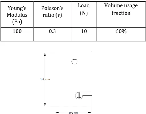
[image:3.595.302.559.142.342.2]This section shows the design domain of a hook structure (Figure 1). The initial design domain is selected as a rectangular plate of dimension 100mm x 150mm with a circular hole at the top, used to introduce a bolt to connect a hook for lifting mechanism and a slot for the access of loading point. Material properties, load used and volume usage fraction are shown in Table 1. The final compliance and optimal shape are acquired with the help of OC in ANSYS.
Table -1: Material properties, Load, Elements and Volume usage fraction for Model 1
Young’s Modulus
(Pa)
Poisson’s ratio (v)
Load (N)
Volume usage fraction
100 0.3 10 60%
Figure 1: Geometry and boundary conditions for model 1 [9] Model 2: Corbel
[image:3.595.303.563.487.652.2]This section shows the design domain of corbel structures, a corbel is a structural piece of stone, wood or metal jutting from a wall to carry a super incumbent weight. Figure 2 represents the design domain of a corbel structure (all dimensions are in mm). Material properties, load used and volume usage fraction are shown in Table 4.2
Table -2: Material properties, Load, Elements and Volume usage fraction for Model 2
Young’s Modulus
(Pa)
Poisson’s ratio (v)
Load (N)
Volume usage fraction
100 0.3 10 50%
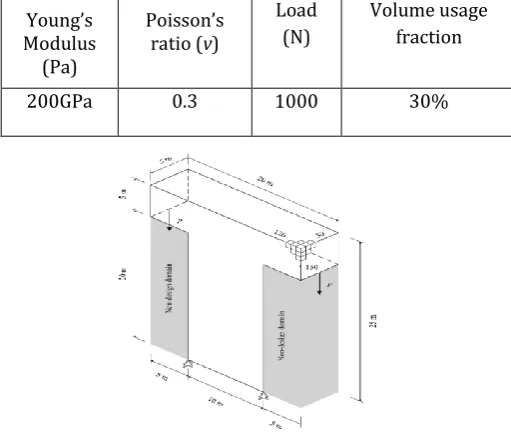
Figure 2: Geometry and boundary conditions for model 2 [10] Model 3: Electric Mast
© 2016, IRJET | Impact Factor value: 4.45 | ISO 9001:2008 Certified Journal
| Page 1486
compliance and optimal shape are acquired with the help of [image:4.595.30.286.158.375.2]OC in ANSYS.
Table -2: Material properties, Load, Elements and Volume usage fraction for Model 2
Young’s Modulus
(Pa)
Poisson’s ratio (v)
Load (N)
Volume usage fraction
200GPa 0.3 1000 30%
Figure 3: Geometry and boundary conditions for model 3 [12]
4. RESULTS
In this section the detail result and FE analysis and optimization of above structures has been presented. Final compliance and optimal shape of the models obtained with the help of ANSYS based Optimality Criterion.
Model 1: Hook
The optimal shape of hook structure obtained through ANSYS (OC) has been shown in figure 4. The final value of compliance after topological optimization has been presented in table 4. The final compliance value is 21.57 N-mm which is obtained by OC in ANSYS after 20 iterations. The optimal shape obtained after topological optimization is quite similar to actual hook, which can be obtained by after shape and size optimization. The blue colour shows that the material has been removed from the initial design domain and the red colour portion shows the final shape obtained after topology optimization.
Table.4 Parameters Obtained during Optimization of Hook Parameters Results
Obtained
Compliance
(N-mm) 21.57
Iterations 20
(a) (b)
[image:4.595.328.548.359.471.2]Figure 4 (a) Optimized shape after topology optimization and (b) Actual shape of hook
Figure 5 shows the plot between compliance versus iteration. The compliance value starts from 61.10 N-m and after second iteration converges to 30.09 N-m which drops to 21.61 N-m after 12th iteration and finally converges to 21.57 N-mm after 20 iterations
.
Figure 5: Compliance vs. iteration plot for model 1
Model 2: Corbel
A corbel is a structural piece of stone, wood or metal jutting from a wall to carry a super incumbent weight. The optimal shape of corbel structure obtained through ANSYS (OC) has been shown in figure 6. The final value of compliance after topological optimization has been presented in table 5.
Table.5 Parameters Obtained during Optimization of corbel
Parameters Results Obtained
Compliance
(N-mm) 30.97
© 2016, IRJET | Impact Factor value: 4.45 | ISO 9001:2008 Certified Journal
| Page 1487
(a) (b)
[image:5.595.276.560.51.285.2]Figure 6 (a) Optimized shape after topology optimization and (b) Actual shape of corbel
Figure 7: Compliance vs. iteration plot for corbel Model 3: Electric mast
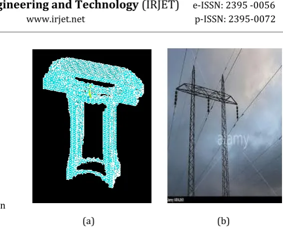
The optimal shape of an electric mast after topology optimization through ANSYS has been shown in figure 8. The final value of compliance and no of iterations has been shown in table 5. The final value of compliance obtained after topology optimization is 11.45e5 N-m obtained after 38 iterations. The optimal shape after topology optimization is quite similar to actual electric mast which can be obtained after shape and size optimization. The compliance vs iterations plot is shown in figure 9.
Table.5 Parameters Obtained during Optimization of Electric mast
Parameters Results Obtained
Compliance (N-
m) 11.45e5
Iterations 38
(a) (b)
Figure 8 (a) Optimized shape after topology optimization and (b) Actual shape of electric mast
Figure 9: Compliance vs. iteration plot for model 3
5. CONCLUSIONS
The following conclusions can be drawn from the present investigation:
Of all the stages of design the conceptual design phase is most critical because it decides the much of the structure’s final design.
The optimized shape after topology optimization of all models is nearly same as that of actual structures.
The value of compliance after optimization is as minimum as possible to make the structure stiffer.
The optimality criteria approach using ANSYS converges very fast in comparison to other topology optimization method.
[image:5.595.35.266.294.402.2] [image:5.595.313.556.336.460.2]© 2016, IRJET | Impact Factor value: 4.45 | ISO 9001:2008 Certified Journal
| Page 1488
Acknowledgement
This work has been done under supervision of Dr. Rakesh Saxena. I am very thankful to him and Dheeraj Gunwant, Ph. D. scholar from GBPUA&T Pantnagar for kindly helping me through this work in ANSYS software with their technical knowledge.
REFERENCES
[
1] A. Diaz and O. Sigmund, (1995), “Checkerboard patterns in layout optimization” Struct. Optim.. Vol: 10: 40-45 [2] C. D. Chapman, (1994) “Structural topology optimization via the genetic algorithm”, Thesis, M. S. Massachusetts Institute of Technology, America.[3] D. Tcherniak and O. Sigmund, (2001)“A web-based topology optimization program” Struct. Multidisc. Optim. Springer-Verlag, Vol 22: 179-187
[4] G. Allaire, F. Jouve and A. M. Toader, (2002) “A level set method for shape optimization” C. R. Acad. Sci. Paris [5] G. I. N. Rozvany, (2008) “A critical review of established methods of structural topology optimization.” Struct. Multidisc. Optim. Springer-Verlag
[6] Gunwant, D. and Misra, A. (2012), “Topology Optimization of sheet metal brackets using ANSYS”. MIT Int. J. of Mech. Eng., Vol. 2. No. 2, Aug. 2012. pp 119-125
[7] J. Du and N. Olhoff, (2005) Topology optimization of continuum structures with respect to simple and multiple Eigen-frequencies. 6th World Congr. Struct. Multidisc. Optim. Brazil
[8] J. Thomsen, (1992) “Topology optimization of structures composed of one or two materials” Struct. Multidisc. Optim., vol: 5: 108-115
[9] Luis Carretero Neches and Adria´n P. Cisilino, (2007), “Topology optimization of 2D elastic structures using boundary elements” Engineering Analysis with Boundary Elements, vol: 32:533-544.
[10] Matteo Bruggi, (2009) “Generating strut-and-tie patterns for reinforced concrete structures using topology optimization” Computers and Structures, vol:87:1483-1495. [11] Matteo Bruggi and Carlo Cinquini, “An alternative truly-mixed formulation to solve pressure load problems in topology optimization” Comput. Methods Appl. Mech. Engg. Vol:198: 1500-1512
[12] Mariano Victoria, Osvaldo M. Querin and Pascual Martí, (2011), “Topology design of three- dimensional continuum structures using isosurfaces” Advances in Engineering Software, vol: 42:671-679.
[13] M. P. Bendsøe, and N. Kikuchi, (1988) “Generating optimal topologies in structural design using a homogenization method” Comput. Meth. Appl.Mech. Eng., vol: 71: 197-224.
[14] M. Rouhi, R. R. Masood and T. N. Williams, (2010) “Element exchange method for topology optimization” Struct. Multidisc. Optim.
[15] O. Sigmund and J. Petersson, (1998) “Numerical instabilities in topology optimization: A survey on procedures
dealing with checkerboards, mesh-dependencies and local minima”, Struct. Optim.. Vol 16: 68-75
[16] O. Sigmund and P. M. Clausen, (2007) “Topology optimization using a mixed formulation: An alternative way to solve pressure load problems” Comput. Meth. Appl. Mech. Eng., Vol 196: 1874-1889
[17] S. F. Rahmatalla and C. C. Swan, (2004) “A Q4/Q4 continuum structural topologyoptimization implementation”, Struct. Multidisc. Optim. Springer-Verlag, Vol 27: 130-135 [18] Stutt gart Research Centre for Simulation Technology (SRC SimTech), Stuttgart University.(2008) “A new adaptive penalization scheme for topology optimization” A. Dadalau, A. Hafla, and A. Verl.
[19] Xia Q., Wang M., (2014) “Topology optimization with pressure load through a level set Method” , Comput. Methods Appl. Mech. Engg., vol: 283: 177-195.