International Conference on Mechanical Engineering Research (ICMER2013), 1-3 July 2013 Bukit Gambang Resort City, Kuantan, Pahang, Malaysia Organized by Faculty of Mechanical Engineering, Universiti Malaysia Pahang Paper ID: P158
EFFECT OF PLENUM CHAMBER DEPTH IN A SWIRLING FLUIDIZED BED
Mohd Al-Hafiz Mohd Nawi1*,2, Mohd Faizal Mohideen Batcha1,2* and Norzelawati Asmuin1
1
Faculty of Mechanical Engineering and Manufacturing,
Universiti Tun Hussein Onn Malaysia, 86400 Parit Raja, Batu Pahat, Johor, Malaysia *Email: [email protected]
Phone: +074537700; Fax: +074536080 2
Energy Technologies Research Group (En-RG),
Universiti Tun Hussein Onn Malaysia, 86400 Parit Raja, Johor, Malaysia. *Email: [email protected]
ABSTRACT
This paper presents the numerical investigation via Computational Fluid Dynamic (CFD) to study the effect of plenum chamber depth on air flow a distribution in a swirling fluidized bed (SFB). A total of 9 simulations were conducted for 3 plenum chamber depths of 175 mm, 350 mm and 525 mm (below the distributor) for 3 different inlets: single, double and triple inlets. Air flow distribution was analyzed based on the tangential velocity distribution ad pressure drop at the distributor outlet. Statistical parameters used in characterizing the air flow distribution were standard deviation, skewness and kurtosis together with system pressure drop. An optimum plenum chamber depth has low statistical values, implying a uniform velocity distribution inside the bed while low pressure drops are necessary to reduce energy loss in the system. The findings yield that plenum chamber with 175 mm depth with via triple inlets suffices both criteria of high uniformity and low pressure drops.
Keywords: Plenum chamber; Swirling fluidized bed; Statistical analysis; Pressure drop
INTRODUCTION
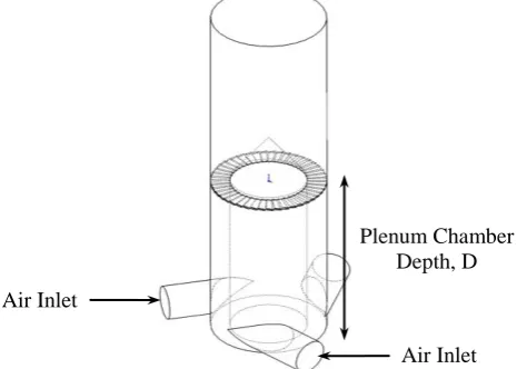
Fluidization is a process by which solid particles are made to behave like a fluid, by being suspended in a gas or liquid. One of the recent developments in providing a variant in fluidized bed operation is the swirling fluidized bed (SFB), which provides swirling motion inside the bed apart from fluidization. In contrast with conventional fluidization, in a SFB the fluidizing gas enters the bed at an inclination to the horizontal directed thus by a suitable design of distributor which as an array of blades with centre body, which forms annular opening as shown in Figure 1 (Batcha et al., 2012).
[image:1.595.181.414.631.797.2]The swirling fluidized bed is an outcome of studies carried out to overcome disadvantages a conventional fluidized bed, particularly the inadequate lateral mixing. It also possesses the ability to well fluidize the Geldart type-D particles which are large in size and usually difficult to fluidize (Mohideen et. al, 2012). Although many aspects of the bed have been studied over the years, less attention have been given on the plenum chamber design. Among related works on the plenum chamber design were by Othman et. al, 2009 and Depypere et. al, 2004 whom have reported their CFD and experimental works. The present work is an extension to the previous study by Batcha et. al, 2013 whom have investigated the aerodynamics of a SFB by taking into the effect of distributor design on velocity distribution and pressure drop inside the bed. As for this study, particular attention is given on the plenum chamber design by varying its depth and number of inlet and their effect on aerodynamic characteristics of the bed. The findings are important to improve the plenum chamber design in the attempt to increase overall performance of the system.
METHODOLOGY
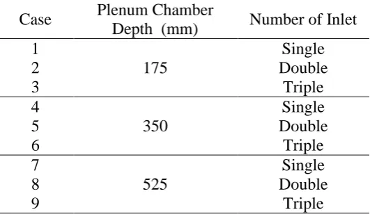
[image:2.595.166.432.444.598.2]Investigation of the air flow distribution in a SFB was conducted using commercial CFD software – FLUENT 6.3. The computation domain and grid generation was developed via GAMBIT 2.4.6. The 60 blades with 15° horizontal inclination has be selected based on previous studies by (Batcha et al., 2012). Two parameters were varied to observe the relation between the plenum chamber depth and number of inlets as shown in Table 1.
Table 1. Configuration of plenum chamber in a swirling fluidized bed
Case Plenum Chamber
Depth (mm) Number of Inlet 1
175
Single
2 Double
3 Triple
4
350
Single
5 Double
6 Triple
7
525
Single
8 Double
9 Triple
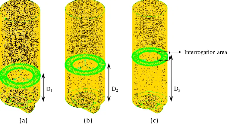
Hence, the Tri:Pave Meshing Scheme was applied to the surface and it allowed GAMBIT 2.4.6 to create a face mesh consisting of irregular triangular mesh elements. The Tet/Hybrid parameter type that specifies tetrahedral, hexahedral, pyramidal and wedge element were defined to the meshing algorithm. The mesh elements in the computation domain as well as the plenum chamber depth is presented in Figure 2.
The mesh quality was be evaluated using the EquiAngle Skew (QEAS) criterion, which are lower or equal to 0.2 for more than 95 % of the control volumes. From this evaluation the mesh quality could be considered satisfactory. In FLUENT environment, the Reynolds Averaged Navier Stokes (RANS) turbulence equation of the (Re-Normalization Group) RNG methods based on model transport equations for the turbulence kinetic energy (k) and its dissipation rate (ε) which is RNG k-ε model has been selected (Versteeg and Malalasekera, 2007). This turbulence model is similar to the semi-empirical model namely standard k-ε model but has additional term in its dissipation rate (ε) equation that significantly improves the accuracy for rapidly strained flows (Versteeg and Malalasekera, 2007). Apart from this, it also provides an analytical formula for turbulence Prandtl numbers and also the effect of swirl on turbulence (Safiah et al., 2008). A second-order upwind scheme was selected for the discreatisation of the momentum equations which is suitable to moderate swirl and SIMPLE algorithm have be applied to solve the pressure-velocity coupling algorithms in the simulation.
The analyze the flow distribution inside the SFB due to the effect of varying plenum chamber depth, three statistical parameters were applied in this study; the standard deviation, σ, skewness, S and kurtosis, K. Similar method was proposed by Othman et al., 2010. Standard deviation denotes the variation to the mean value of the probability distribution while skewness is a measure of asymmetry of the probability distribution. As for the kurtosis, it is a measure whether the data are peaked or flat, relative to normal distribution. In the present study, a combination of low standard deviation, skewness and kurtosis is desired as it implies high uniformity of velocity distribution inside the bed. The equations for above mentioned statistical parameters are as follows (Joanest and Gill, 1998):
[image:3.595.164.541.170.383.2](a) (b) (c)
Figure 2. Computational domain in CFD for plenum chamber with various depths: (a) D1 = 175 mm; (b) D2 = 350 mm; (c) D3 = 525 mm
D1 D2 D3
Standard deviation:
5 . 0
1
) (
1 1
N Vi VmeanN
(1)
Skewness:
N i mean
N V V S
1
3 3
) 1 (
) (
(2)
Kurtosis:
N i m ean
N V V K
1
4 4
) 1 (
) (
(3)
where N is the number of data points, σ is the standard deviation, S is the skewness, K is the kurtosis, Vi is the univariate data of velocity distribution and Vmean is the mean velocity of velocity distribution.
RESULT AND DISCUSSION
Upon completion of simulation, data was extracted on a horizontal plane, 10 mm above the distributor as in Figure 2 since this is the area where gas-solid contact starts in an actual bed. Discussion in this paper however is limited to tangential velocity alone because it has the highest magnitude and responsible for swirling in the annular region of the bed. The velocity profile for various plenum chamber depths and number of inlets were shown in Figure 3.
(a)
Generally, the velocity profile increases along the radius towards the bed wall as a result of swirling motion which generates centrifugal force. This centrifugal force pushes the air to mass at outer periphery towards the bed wall, hence higher momentum is present at this location. The effect is more pronounced at higher inlet velocities as reported by Faizal et al, 2012. However, the velocity of air is zero at the wall itself due to no-slip condition as a result of shear force at wall.
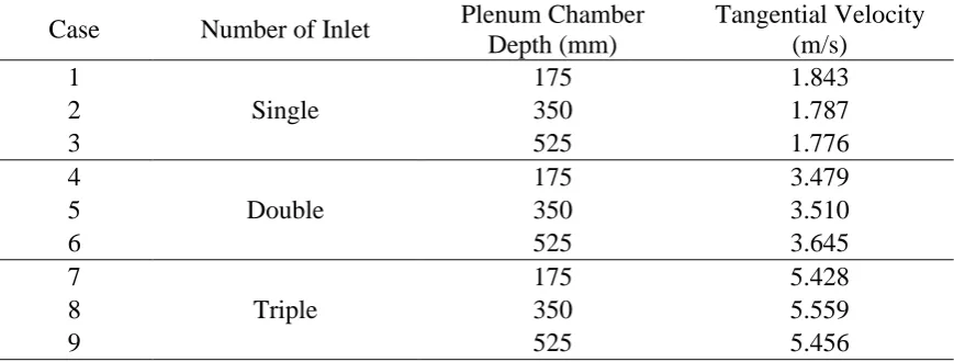
[image:5.595.147.452.88.284.2]It was evident that more inlets result in higher velocity magnitude due to the increase in overall mass flowrate. For single inlet as in Figure 3 (a), lower plenum chamber depth (175 mm) result in noticeable skewed profile but the velocity distribution becomes almost identical as the number of inlet increases (Figure 3 (c)). The tangential velocity magnitude for various plenum chamber is summarized in Table 2 below.
Table 2. Tangential velocity magnitude for various plenum chamber configuration
Case Number of Inlet Plenum Chamber
Depth (mm)
Tangential Velocity (m/s)
1
Single
175 1.843
2 350 1.787
3 525 1.776
4
Double
175 3.479
5 350 3.510
6 525 3.645
7
Triple
175 5.428
8 350 5.559
9 525 5.456
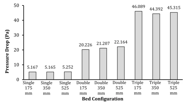
Apart from velocity distribution, pressure drop of the system were also extracted from the simulation to gain a better understanding of the system behavior. The pressure
[image:5.595.81.516.541.706.2](c)
drops were distributor pressure drop, which was extracted at equal distances of 10 mm below and above the distributor blades. The findings were in Figure 4
[image:6.595.110.482.128.333.2]Naturally the higher number of inlets have higher pressure drop due to increasing amount of air flowrate. Interestingly, only small variation in pressure drop found for different plenum chamber. This shows the strong dependence of pressure drop on air flowrate alone, while plenum chamber depth has negligible effect. From both velocity distribution and pressure drop values obtained, a statistical analysis was conducted to arrive at the optimum design of the plenum chamber from all 9 configurations. The calculated statistical parameters are as in Table 3.
Table 3. Statistical parameters
Case Number of Tangential Entry Plenum Chamber Depth (mm) Standard Deviation of Velocity (σ)
Skewness (S)
Kurtosis (K)
1 Single 175 0.39401 -2.28685 7.5284
2 Single 350 0.34553 -2.81901 1.23656
3 Single 525 0.38584 -2.42711 6.27859
4 Double 175 0.59668 -2.72354 12.2002
5 Double 350 0.77327 -2.82005 8.7888
6 Double 525 0.72372 -3.15304 11.7699
7 Triple 175 1.08481 -2.50476 7.4591
8 Triple 350 1.02326 -2.39202 8.2536
9 Triple 525 0.96792 -2.53916 9.0162
From the statistical analysis summary in Table 2 above, it was found that case 2 has better velocity distribution in relative to others. This was indicated by the low standard deviation and kurtosis, implying small variation in tangential velocity as well as less local velocity peaks (flatter velocity profile). However, the air flow in the studied
5.167 5.165 5.252
20.226 21.207 22.164
46.089 44.392 45.315
0 10 20 30 40 50
1 2 3 4 5 6 7 8 9
[image:6.595.81.516.499.681.2]Pre ssu re D rop (Pa) Bed Configuration Single 175 mm Single 350 mm Single 525 mm Double 175 mm Double 350 mm Double 525 mm Triple 175 mm Triple 525 mm Triple 350 mm
to the centrifugal force from the swirling motion and hence evident for all other configurations.
CONCLUSION
CFD simulation is an effective method to understand the complex phenomena of velocity distribution such as in the swirling fluidized bed. These aerodynamic characteristics are imperative in optimizing the plenum chamber design towards increasing the overall efficiency of the system. It can be concluded that number of inlet has stronger influence on velocity distribution and distributor pressure drop in comparison to plenum chamber depth. From the statistical point of view, case 2: single inlet with 350 mm depth can be considered the best configuration in the preset study.
ACKNOWLEDGEMENT
The authors would like to extend their deepest appreciation to Universiti Tun Hussein Onn Malaysia (UTHM) for sponsoring the research under Postgraduate Incentive Fund Vot No. 1024 and the related facilities and equipment in the Energy Technologies Research Group (En-RG).
REFERENCES
Batcha, M.F.M., Nawi, M.A.M., Sulaiman, S.A. and Raghavan, V.R. 2013. Numerical Investigation of Airflow in a Swirling Fluidized Bed, Asian Journal of Scientific Research, 6 (2): 157 – 166.
Batcha, M.F.M., Sreenivasan, B., Sulaiman, S.A. and Raghavan, V.R. 2012. Heat Transfer in a Swirling Fluidized Bed with Geldart Type-D Particles, Korean J. Chem. Eng., 29(7): 862-867.
Depypere, F., Pieters, J.G. and Dewettinck, K. 2004. CFD Analysis of Air Distribution in Fluidised Bed Equipment, Powder Tech., 145, 176 – 189.
Faizal M., Seri S.M., Al-Hafiz, M. and Raghavan, V.R. 2012. CFD Studies on Velocity Distribution of Air in a Swirling Fluidized Bed. Advanced Materials Research, 468-471: 25-29
Joanest, D.N. and C.A. Gill. 1998. Comparing measures of sample Skewness and Kurtosis. The Statistician, 47 (1): 183-189.
Mohideen, M.F., Seri, S.M. and Raghavan, V.R. 2012. Fluidization of Geldart Type-D Particles in a Swirling Fluidized Bed, Applied Mechanics and Materials, 110-116: 3720 – 3727.
Othman, S., Wahab, A. A., & Raghavan, V. R. (2010). Statistical Analysis on the Design of Flow Modifying Centre-Bodies in a Plenum Chamber. CFD Letters, 1 (2), 78-86.
Safiah O., Wahab A.A. and V.R. Raghavan. 2008. Numerical Study of The Plenum Chamber of a Swirling Fluidized Bed. Proceedings of International Conference on Mechanical & Manufacturing Engineering, Johor Bahru, Malaysia, ISBN: 97-98-2963-59-2.