Systems
GA33-1529-0 File No. 5370-03
IBM
3203
Printer Model
5
Preface
ii
This publication provides reference and operating information for users of the IBM 3203 Model
5
Printer. It is written mainly for system planners, programmers, and operators, but may also be of interest to system supervisors and engineers.The publication provides a general introduction to the 3203 Model
5,
its components and method of operation, and explains the various operat i ng procedures. The "Programm i ng I nformat i on" sect ion descr i bes the commands used to control the printer, the status and senseinformation returned to the system, and the error recovery procedures.
The reader should be familiar with the system to which the printer is attached. For system and programming information, refer to the
publications listed in the bibliography for the using system.
First Edition (January 1979)
Changes are periodically made to the information herein; any such changes will be reported in subsequent revisions or Technical Newsletters.
Requests for copies of IBM publications should be made to your IBM representative or to the IBM branch office serving your locality.
This manual was prepared by the IBM System Products Division, Product Publications, Department 3179, Schoenaicher Strasse 220,7030
Boeblingen, Germany. A form for reader's comments is provided at the back of this publication. If the form has been removed, comments may be sent to the above address. Comments become the property of IBM.
Contents
Introduction . . . Method of Printing.
Printing Speed . . . . Attachment to System .
Buffers . . . .
Forms and Ribbon . . Forms Fastening. Paper Weight . .
Single-Part Forms . . Multiple-Part Forms. Continuous Card Forms. Ribbon . . . .
1 2 3 6 6 7 7 8 8 8 9 9
IBM 1416 Interchangeable Train Cartridge 11
11
Type Size . . . .
Standard Character Sets. • 14
Dualing . . . . • • 14
Universal Character Set. · • • • • • 16
Preferred Character Set . . . . • • • • • • • • 16 Examples of PCS Timings . . · . . . • • . . . 17
Components . . . . Forms Carr i age . .
Paper Compartment. . . . .
Ribbon Drive and Ribbon Shield Forms Stacker . . .
Stacker Components .
. • • • . 18
• • • • • . 19
. . . . . 20 . • . . . 20 · . 20 · 21 · 22
Vacuum Cleaning System.
Acoustic Enclosure • • • • • • • • • 23
Usage Meter. . • • 23
Machine Covers and Safety. • • 23
Information for Operators. . . 25
Aux i 1 i ary Operator Pane 1 . . . . 26
Enable/Disable Switch. . . 26
Local/Remote Switch. . . . • . . . 26
Byte/Burst Mode Switch. . • . . . . 26
Reset Switch . . . 26
Power On/Off Switch. . . . . . . . 26
Unit Emergency Switch. . . . 27
-5V, +5V, +8.5V Lights. . 27
Power On Light. • . . . • 27
Disable Light . . . • . . . . • • . . . • . . 27 Operator Panel Switches, Keys, and Lights . . . • . • 27
START Key. . . 27
SINGLE CYCLE Key . 27
STOP Key . . . • . 28
CARRIAGE RESTORE Key. . . • • . . 28
CARRIAGE SPACE Key. . . . . . . 28
Page of GA33-1529-0 Revised 9 Nov 1979
By TNL GN33-1730
iv
Reset Counter Switch . . . STACKER DOWN Key (Rear) . . POWER ON Light.
INTERLOCK Light. FORMS Light. READY Light. . . CHECK Light. . . STACKER Light. . Manual Controls . .
Forms Advance Knob . . . . . • • • Vertical Print Registration Knob. Horizontal Print Adjustment Knob. Print Density Kno6 . . . • . . • . Forms Thickness Knob . . . • .
• • • • 28 • • 29 • • 29 • • • . • • 29 • • 29 • • • • 30 • • 30 • • 30 31 • • 31 • 31 • • 31 .- 32
Paper Brake Adjustment Lever . . . • . . • . .
33 33
Operating Procedures . . . • . • .
Forms Loading. . . . . • •
Power-Assisted Forms Stacker . . . • •
• 33 33 • • 39
Adjustment of Power-Assisted Stacker.
Starting the First Print Job . . . • • • . · 43 44
Print Cartridge Changing.. . . . • .
UCS Cartridge Mounting . . Cleaning the Print Train. Ribbon Changing . •
Vacuum Cleaning • • . • . .
Programming Information. Commands . . . . .
Write Commarids . • . • .
44
• 44
47 47
49
• • 51 • 51 • 51
Carriage Control Commands.. . • . • . .". . . 53
Initializing and Diagnostic Commands. Dualing and Uncomparable Character Table .•
Checking by the DUCT . . •
Dualing . • . • • . . . . • . . • •
· 53 58 58
• • 59
How to Program the DUCT . . • • • Programming the Forms Control Buffer
Indexing Byte . . . • • •
. . . · 59
Carriage Programming Options.
Status Information. . • • •
Unit Status . . . • • • • • . • . • Channel Status . .
Sense Information • .
Sense Byte 0: Summary. . . • • .
Sense Byte 1: Programming Information. Sense Byte 2: Mechanical • • • . . • Sense Byte
3:
Electrical" • . • • • .Sense Byte
4:
Device Identification ••Sense Bytes
5
to 19: Maintenance . • Sense Bytes 20 to 22: Unassigned . . • Sense Byte 23: Device Identiflcation Error Recovery . . . . . . , • .Unit Check in CSW • • . . .
• 61
· . 63
• 64
· 67 · • 67
• • 68 • • 68
· 69 • • • 71
73
Printing for Optical Character Recognition
( OCR) . • • . . . • • • • 79
OCR Character Sets • . '. • . . • • • . • 79
OCR Paper Requirements • • . • • • . • • . ~ibbon Recommendations . . . .
Recommendations and Considerations.
· . 79 • • • 79 · 80
Character Print Quality • . . . . 81
Character Outline Limits • . Ch~racter Stroke Width . Vo ids. • • • • . • . . Character Spacing • . . Character Misalignment. High Speed Print Quality. Print Quality Control . • .
. .'.
Print Quality' Test and Optimization. Quality Control During Printing • • .
Appendix A. Extended Binary-Coded-Decimal
• • 81 • • • 82
• 82 82 · 83 · 83 · • 88 • • 88 • • • • • 90
Interchange Code (EBCDIC) • • • • • • • A1
Appendix B. 3203 Model 5 Sense Byte
Summary • . • . • . . • • B 1
Appendix
c.
3203-5 Programming Notes ClPage of GA33-1529-0 Revised 31 Aug 1979 By TNL GN33-1732
vi
Illustrations
Figure Number Frontis. 1 • 2.3.
4.
5.
6.
7.
8.
9.
10.11 •
12. 13.
14.
15. 16. 17. 18. 19. 20. 21 • 22. 23.24.
25.
26.
27.
28.
29.
30. 31 • 32.33.
34.
35.
36.
37.
38.
39.
40.
41.
42.
43.
44. TitleIBM 3203 Printer Model
5 . . .
Main Elements of 3203 Printer • • • Printing Method of 3203 Printer ••.
.
.
Paper Path through 3203. . . . . . Formulas to Calculate Printing Speed . • . .
Time Factors for Line Spacing and Skipping . . • • System At tachment . . . • • . . . • . •
Schematic of Train Printing Mechanism . . .
Train Arrangements. . . . . . . . 12, EBCDIC Codes for Characters Dualed on the 3203 .
EBCDIC Characters Printed by 48AN or 48HN Train . . Preferred Character Set (PCS) Sequences on AN Train . . Printing Speed for Preferred Character Set.
Forms Carriage. . . • . . . . . . Ribbon • . . . • . . . . Rear Unit with Forms Stacker . . . . Vacuum Cleaning System. . . . . . . .
Operating Keys, Lights, and Switches . . . . Manual Controls . . • . . . Fine Adjustment of Forms in Horizontal Direction. Paper Brake Adjustment Lever . . . . Opening the Swing Gate. . . . . . . . Pos it ion i ng a Tractor. . . •
Closing a Tractor Cover . . • Hammer Position Indicator . • Printing Area . . . • . • . •
Initial Vertical Alignment of Formsi • . • . . . Positioning New Forms . . . .
Adjustable Stacker Parts . . . • • . Raising the Stacker Tray • .
Paper Pile Sensing Device . . . . Hinged Paper Rail (Up Position).
Stacker Chute. . . • . . . . Recommended Settings of Paper Rail and Chute . . . . . Removing the Print Cartridge. . . . . . Mounting the Print Cartridge . . •
Installing th~ Ribbon . . . . Vacuum Cleaning by Hand • . . . . Vacuum Cleaning Waste Container. Wr i te Commands . . . • . . . . Carr i age Contra 1 Commands. . • • .
Initializing and Diagnostic Commands. Setting DUCT Bits for Printable Graphics.
Forms Control Buffer Codes • • . . . . . . Recommended Carriage Control . • • . . . .
45. Alternative Carriage Control ( I )
46. Alternative Carriage Control (2)
47. Basis of Sense Bytes
· · ·
· · ·
48. Ribbon Protector for OCR Printing.
. .
·
49. Use of Minimum/Maximum COls (Best Fit)
50. Spots and Voids.
·
·
·
· ·
51 . Print Deviations
· ·
·
·
·
52. Acceptable Printing.
·
·
·
·
.
·
53~ Heavy Printing
.
·
·
·
·
·
· ·
54. Weak Printing.
. · ·
·
·
· · · ·
55. Printing from a Coarse Ribbon.
·
·
· ·
·
56. light Tops to Characters
· · ·
57. light Bottoms to Characters.
·
58. left Character Cutoff.
59~ Right Character Cutoff
· · · ·
60. Vertical Stroke Width.
· ·
·
61. Forms Thickness Control Optimization
.
A1. EBCDIC Chart
· · · ·
·
A2. Chart Quadrants.
· · · ·
·
A30 Examples of Chart Usage.
·
Abbreviations CCW COL CSW DOS/VS DUCT EBCDIC FCB lb 1 P i lpm mm OCR OMR PCS Sll TIO UCS UCSB
channel command word character outline limits channel status word
disk operating system/virtual storage dualing and uncomparable character table
.extended binary-coded-decimal interchange code forms control buffer
pound
lines per inch lines per minute mi 11 imeter
optical character recognition optical mark reading
preferred character set suppress length indication test input/output
universal character set
universal character set buffer
65 66
·
69· ·
80 82· ·
82 84·
·
·
·
85· ·
·
·
85· · ·
85· ·
86 86·
·
·
·
86 87 87 89·
89·
·
A2· ·
A3· ·
A3Introduction
The IBM 3203 Printer Model 5 (Frontispiece) produces printed records, controlled by a System/370 data channel; or an equivalent interface. A channel attachment located in the printer accepts the commands from the channel and controls printer operation. The 3203-5 is a line printer; that is, its unit of printing is the line.
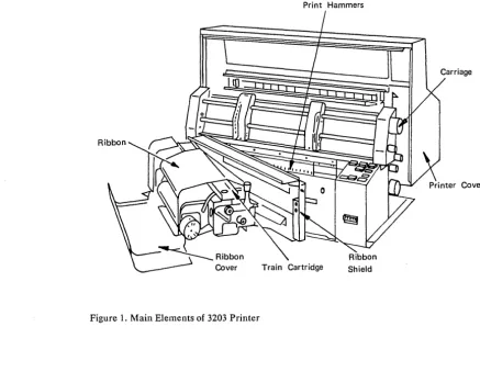
The main elements of the 3203-5 Printer (Figure 1) are a print hammer unit, an interchangeable train cartridge containing 240 characters, and a tapeless carriage under program control.
The 3203-5 has a line length of 335.3 mm (13.2 inches), or 132
characters. It pr i nts at 5 i x or eight 1 i nes per inch. I f the 3203-5 is
equipped with the 48-character set train cartridge, it prints at a nominal speed of 1200 lines per minute.
The 3203-5 uses the IBM 1416 Interchangeable Train Cartridge, which is also used on the IBM 1403 Printer Model N1. The universal character set (UCS) is a standard feature.
Print Hammers
Figure 1. Main Elements of 3203 Printer
[image:10.618.64.501.364.712.2]METHOD OF PRINTING
Characters are printed by the impact of hammers against the back of the form, forcing the form and ribbon against the typeface to print the characters. The printing method of the 3203-5 is shown in Figure
2.
1 Print train rotates, presenting Armature
each cha~acter to each Form / " Pivot 2 Magnetic coil is hammer In turn.
W
activated whenRibbon 0 character is
\
0 the desired
positioned
--..,....----'---,...,
L.
1111 at hammer.~(!g~0H: U~
~
i'Armature pushes~ " th' p",h<ad.
!
4~"p;,ot"nd
I presses the paper and Train CartridgeFront: Rear ribbon against the train.
Figure 2. Printing Method of 3203 Printer
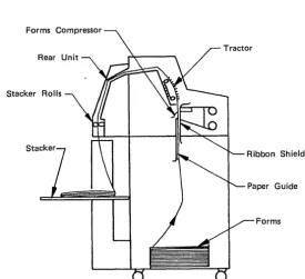
When aline has been printed the paper is transported under system and program control. The paper passes through the printer as shown in Figure 3.
Forms Compressor
Stacker Rolls
Stack
Ribbon Shield
Forms
Figure 3. Paper Path through 3203
[image:11.618.80.355.414.664.2]PRINTING SPEED
The printing speed is defined as the number of lines printed per minute (lpm). It depends upon several factors such as the number of
identical characters on the print train, the line spacing, and the page format. Using a 48-character set print train, the 3203 can print at a nominal speed of 1200 lpm. Maximum print speed of 1580 lpm can be attained with a character set of 32 characters (see "Preferred Character Setl l) . Any character set with fewer than 32 characters will
also print at 1580 lpm.
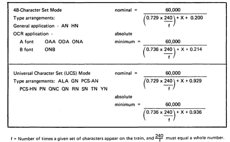
Figure 4 shows the formulas used for calculating the speed of continuous printing.
48-Character Set Mode Type arrangements:
General application - AN HN OCR application
-A font OAA ODA ONA B font ONB
Universal Character Set (UCS) Mode Type arrangements: ALA GN PCS-AN
PCS-HN PN ONC ON RN SN TN YN
nominal = 60,000
(0.729 x 2~0) + X + 0.200
absolute
minimum = 60,000
(0.736 x 2~0) + X + 0.214
nominal = 60,000
absolute minimum =
(0.729 x 2~0) + X + 0.929
60,000
(0.736 x 2~0) + X + 0_936
f = Number of times a given set of characters appear on the train, and 2~O must equal a whole number.
x = time factor for spacing or skipping (see Figure 5).
Figure 4. Formulas to Calculate Printing Speed
The formulas contain a variable for the immediate carriage movement that occurs when the print line is complete. The actual printing
speeds can therefore vary from the nominal speeds given, and are often
greater. Depending on whether single spacing or skipping operations
are performed, the appropriate time factor (X in the formulas shown in Figure 4) must be added in the denominator of the formulas.
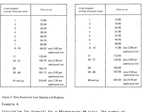
Figure 5 shows the time factors for the number of 1 ines skipped. The times vary according to the number of lines, six or eight, printed per inch.
[image:12.613.134.525.262.504.2]Lines skipped
Time in ms at 6/pi (tines per inch)
Lines skipped
Time in ms at 8 /pi (tines per inch)
1 13.85 1 13.85
2 22.40 2 18.40
3 30.40 3 24.90
4 38.30 4 31.40
5 46.20 5 37.90
6 54.10 6 44.40
7 80.90 -7 68.80
8·16 84.52 plus 3.62 per 8·16 71.86 plus 3.06 per additional line additional line
17 132.40 17 112.50
18·27 135.70 plus 3.30 per 18 - 27 115.30 plus 2.80 per additional line additional line 28 194.10 28 165.00
29·66 197.13 plus 3.03 per 29 - 88 167.56 plus 2.56 per additional line additional line 67 and up 316.49 plus 7.25 per 89 and up 324.03 plus 5.43 per
additional line additional line
Figure 5. Time Factors for Line Spacing and Skipping
Example A
Calculation (by formula) for a 48-character AN train. The number of times the complete 48 AN configuration appears on the train is 5.
240/48
=
5 presentations of 48 AN set.Therefore, f equals 5, and X (for continuous printing and single line spacing at 6 or 8 lpi) equals 13.850.
Nominal speed (lpm)
=
60,000
(0.729 x 240) + 13.850 + 0.200
-5-4 3203 Model 5 Component Description and Operator's Guide
[image:13.617.35.513.63.439.2]Example B
Calculation for a 48 AN train, printing continuously with double spacing at 6 lpi:
f
=
5
X=
22.40Nominal speed (lpm)
60,000
- - - = 1041
(0.729 x 240) + 22.400 + 0.200
-5-The same configuration, but printing continuously with double spacing at 8 lpi:
f
5
X
=
18.400Nominal speed (lpm)
60,000
(0.729 x 240) + 18.400 + 0.200
5
1119
ATTACHMENT TO SYSTEM
Buffers
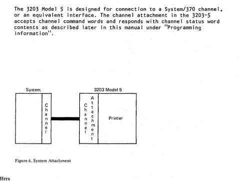
The 3203 Model 5 is designed for connection to a System/370 channel, or an equivalent interface. The channel attachment in the 3203-5 accepts channel command words and responds with channel status word contents as described later in this manual under "Programming.
Information".
System 3203 Model 5
A
C C t t
h h a
a a c
n n h Printer
n n m
e e e
I I n
t
Figure 6. System Attachment
The 3203 Model 5 has several buffers that control the operation of the printer.
• The print line buffer contains the 132 characters which form the line or data to be printed~The characters are stored in EBCDIC code (see Appendix A). The print data buffer is loaded when a
'Write ' command is given to the 3203-5. .
• The universal character set buffer contains an image in EBCDIC code of the 240 characters on the print train, and contains'the 64 bytes
of the dualing and uncomparable character table. The train buffer
is loaded by the 'Load UCSB ' command.
• The forms control buffer contains bytes of information for
controlling the movement of the ~arriage. The forms control buffer
is loaded by the 'Load FCB ' command.'
[image:15.617.54.534.95.458.2]Forms and Ribbon
The 3203-5 prints on continuous forms consisting of one to four parts (copies). Forms consisting of more than four parts should be tested under operating conditions to determine acceptability. The forms are punched at the margins to fit onto the pin-feed carriage tractors. They can be designed to permit printing in almost any desired arrangement. Recommendations are given in the IBM publication.EQ[.Dl~
Design Reference Guide for Printers, GA24-3488.
The forms may be up to 610 mm (24 inches) long and 508 mm (20 inches) wide from edge to edge. A maximum width of 452 mm (17-25/32 inches) is
recommended as this allows greater flexibility in the use of the print area.
Note: When a length greater than 432 mm (17 inches) is used, the door of the forms compartment must be kept open. When a length greater than 366 mm (14 inches) is used, the acoustic enclosure must be left open.
The minimum forms length is 76,2 mm (3 inches), and the minimum width is 89 mm (3-1/2 inches). Short forms should be grouped to improve stacking, the main folds being at intervals of between 203 mm (8
inches) and 304 mm (12 inches).
The operator may have to remain in attendance at the stacker if:
• Card stock is being printed.
• The relative humidity is more than 65% or less than 20%. (Below 8% relative humidity, forms feeding is not guaranteed.)
• The pile of forms on the stacker tray is higher than 304 mm (12 inches).
Paper suitable for optical character readers is specified 'in the publications listed in "OCR Paper Requirements" under "Printing for Optical Character Recognition (OCR)".
FORMS FASTENING
Fastening must prevent the copies from shifting without impairing the feeding or printing al ignment of the forms. The fastening method is determined by the width and length of the forms and the number of parts.
Multiple-part forms should be fastened on both sides and only in the margin areas. Single-side fastening is not recommended. However, if this method is used, the fastening must be on the right-hand side. Carbons must also be fastened on the right-hand side.
The forms must not contain rigid staples in the print area. There must be no metal staples in the area of the cartridge and the hammer
unit.
A leader is normally required for pre-numbered forms.
PAPER WEIGHT
The required paper weight depends on the number of parts to the forms, as follows:
Single-Part Forms
Paper weight 14 to 35 lbs (17x22-500)
(53 to 130 grams/square meter)
Maximum thickness 0.23 mm (0.009 inch)
l"fultiple-Part Forms·
Maximum thickness 0.51 mm (0.020 inch)
Maximum variation 0.30 mm (0.012 inch) of forms thickness within form
Four-part forms
Paper weight
Carbon paper weight
Forms with more than four parts
Paper weight
Carbon paper weight
11 to 13 lbs (17x22-500) (41 to 49 grams/square meter) Sulphide bond
6 to 9 lbs (20x30-500)
(14 to 21 grams/square meter) Kraft medium carbon paper
Approximately 11 lbs (17x22-500) (41 grams/square meter)
Approximately 6 lbs (20x30-500)
(14 grams/square meter)
Smooth-surfaced papers usually produce better copies. The forms
should be tested under operating conditions for trouble-free feeding and 1 eg i b i 1 it Y .
Continuous Card Forms
Card weight
99
lbs(24x36-500)
(161
grams/square meter)Marginally-punched long-grain card stock with 2,
3,
or4
cards per fold, in widths of216
mm(8-1/2
inches),378
mm(14-7/8
inches) and403
mm(15-7/8
inches) is recommended. Result are better with long-grain stock than with short-grain stock.RIBBON
The ribbon recommended for the
3203-5
is IBMPIN 457937
or an approved equivalent. The ribbon is357
mm(14-1/16
inches) wide. Forapp 1 i cat ions wh i ch requ i re OCR pr i nt qua 1 i ty, see IIR i bbon
Recommenda t ions II under lip r in t i ng for Opt i ca 1 Cha r ac ter Recogn i t: ion (OCR)". If the ribbon protector described in the above section is installed, it must be retracted during operation with a standard ribbon.
IBM 1416 Interchangeable Train Cartridge
The 1416 Interchangeable Train Cartridge is used on the 3203-5. It contains 240 characters arranged on 80 type slugs with three
characters per slug (Figure
7).
The cartridge is mounted on the swing gate. When the train moves, it is continuously cleaned by a vacuum cleaning system.Figure 7. Schematic of Train Printing Mechanism
TYPE SIZE
Complete train composed of five sections (80 type slugs with three characters per slug)
The standard type is 2.413 mm (0.095 inch) high. Type styles with a nominal height of 2.007 mm (0.079 inch) are also available and should be used when printing at eight lines per inch. The horizontal spacing of characters on the form is 2.54 mm (0.1 inch) from center to center.
[image:20.620.75.570.165.481.2]"AN" (48 "A" GRAPHICS) 5 IDENTICAL ARRAYS
"HN" (48 "H" GRAPHICS) 5 IDENTICAL ARRAYS
"OAA" (48 "OCR A" FONT GRAPHICS) 5 IDENTICAL ARRAYS
"aDA" (48 GRAPHICS, 10 "OCRA" NUMERICS) 5 IDENTICAL ARRAYS
"arM" (48 GRAPHICS, 10 + 3 "OCR·A" NUMERICS) 5 IDENTICAL ARRAYS
"OAB" (48 GRAPHICS. 10 + 3 "OCR B" NUMERICS) 5 IDENTICAL ARRAYS (see Note 2)
"OAB" (48 GRAPHICS. 10 + 3 "OCR B" NUMERICS) 5 IDENTICAL ARRAYS (WORLD TRADE ONLY) (see Note 3)
"ONB" (48 GRAPHICS, 10' 3 "OCR 8" NUMERICS) 5 IDENTICAL ARRAYS
"ALA" (162 GRAPHICS 78 PREFERRED)
1241 ABC IOEF GHI JKL )dNO PQR 1ST UVW XYZ ~IE~ [ ] ! -" : . ,
.
4:56 789 Oq:.bc del Ahi j k 1 mno pqr ?s t UVW xyz .12}1 a~ "
·'.i
E. ) ( ; 1 2 ;, " :I 6 789 0-+001;. ( )H
=9 t /tel @tlf *iil$ 12;' 456 789 0-+
"GN" (63 GRAPHICS 57 PREFERRF[)1
"PCS·AN" (49 GRAPHICS). 3LEVEL SET. 48 "A" GRAPHICS
I
~~~~~~~~~c.*~~~~~~~~~~1:$% l~1
'I . - - :;.: - - - ---r -
~
~~-~ --~---~~
Notes:
• ? "
, .. ....,
" ...
.
...
... ) ( • • • 0 _ =
,,",v , .. -- - 1
, ) (
><+
---Character Set Print Mode
48 (see Note 1 )
48 (see Note 1 )
48 (see Note 1)
48 (see Note 1)
48 (see Note 1)
48
48
48 (see Note 1)
120/240
60/120
30/60/120
1. These arran~ements print in the "48 character set mode"; all others print in the "UCS mode". For details refer to section "Printing Speed" in the "Introduction".
2. A timing mark dash (graphic -) is available instead of the graphic> to print timing marks on documents for reading by the IBM 3886 Optical Chartlcter Reader.
3. The graphics 0 Or 1> may be substituted for apostrophe graphic' and A, N, or JC for the equals symbol =.
Figure 8. (Part 1 of 2) Train Arrangements (Printout Representation)
12 3203 Model 5 Component Description and Operator's Guide
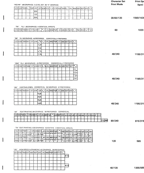
"PN" PL/I 160 GRAPHICS) 4 IDENTICAL ARRAYS
"ON" PUI (60 GRAPHICS· 45 PREFERREDI SCIENTIFICALLY PREFERRED
123 4~6 789 OXY 1ST UIIW -"$ I:t, • JKL JoANO POR -z( ABC DEF GHI +.1
<; ....
?)ci)
...,'£.
1:"10
"QNC" PL/I (60 GRAPHICS· 45 PREFERRED) COMMERCIALLY PREFERRED
-123 4~6 789 O#iil 1ST UVW XYZ !:. .·A JKL MNO POA -$J;: ABC DEF GHT "f-I:
< ;-.
, 1>
1+(
"RN" FORTRAN·COBOL· COMMERCIAL (52 GRAPHICS· 47 PRE FE R RED,I
123 456 769 OXY 1ST UVW • ci) $ * •. JKL MNO PQ,A -z( ABC DEF GHI +.1
"l.ci)$
Nci)S
OoilS
toilS
"~N" TEXT PRINTING (R4 GRAPHICS 78 PREFERREDI COMMERCIAL
"TN" TEXT PRINTING (120 GRAPHICSI SCIENTIFIC 21DENTICAL ARRAYS
123 " 56 789 0". 1ST uv .... XYZ ... £. JKL MNC PQR _": ABC DEf GHI +ab cd. fvh IJ It
opq r s t uvw xyz ci)' ? :! I $':'% O'z » . , 171 .0-t ( I o~(
'''-+ )( s :1:'. ()) (
....
,. ....123 "56 789 0=. 1ST UVW XYZ .N£. JKL MNC PQR _II: ABC DEf GHI +ab cd. fvh IJk
opq rst uvw x y z ci)'? : ~ I S~:·1. 0' I J . , 171 .0-t I I O~I
I" ~ )( S :1:'. (]) {
....
,. .""YN" HIGH SPEED ALPHAMERIC (42 GRAPHICS, 39 PREFERREDI
123 456 789 OST ABC DEF GHI J KL MNO POR UVW XYZ * •.
N-si
"'-sl
Figure 8. (Part 2 of 2) Train Arrangements (Printout Representation)
lmn _-I lmn _-I Character Set Print Mode 30/60/120 60 48/240 48/240 48/240 80/240 120 40/120
Page of GA33-1529-0 Revised 31 Aug 1979 ByTNL GN33-1732 Print Speed (lpm) 1560/1020/585 1020 1195/315 1195/315 1195/315 815/315 585 1355/585
[image:22.629.61.563.84.686.2]Page of GA33:-1529·0 Revised 31 Aug 1979 By TNL GN33·1732
STANDARD CHARAcrER SETS
DuaJiog
The train cartridge cont~ins 240- characters whfch are 'arranged on, type slugs in groups of,th~ee. The ar~angement is ,usually five identical, arrays of 48 characters. The basi~ charac~er arrangements are "A" (Standard Binary Coded Decimal Interchange Code) or
"H"
(for FORTRAN or COBOL). Each of these character arrangements allow 48 different characters to be printed at each print position: 26 alphabetic, 10 numer i c, and 12 spec i a I characters. Figure 8 shows a var i ety of these, arrangements.The AN and HN tr~ins are i~ent;cal except for four character positions. On the ANtra;n these four positions contain:
a
%@
#
whereas the
HN
train has:) ( I
=
This means, for example, that the HN train has the right-hand parenthesis graphic where the AN train has the lozenge. This
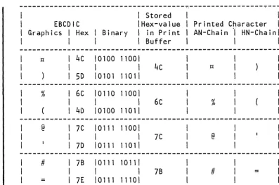
right-hand parenthesis graphic is printed lfthe corresponding EBCDIC code hex 4C (see Figure 9) is sent to a printer equipped with the HN train~ If hex 4C is sent to a printer equipped with the AN train the lozenge is printed. This relationship is called dualing (pairing). Dualing is a stahdard feature for the 48-character set. All possible combinations are shown in Figures ',and 10.
Apart from the exception stated in Note 3 on Figure 10, th~ codes outside the bold lin~s of the Figure are considered to be undefihed. Undefined codes generally cause an unspecified graphic to be printed. This graphic may be different from the one printed, displayed, or otherwise recor~ed by anqther output device. IBH ieserves the right to change such undefined graphics printed by the 3203~5 from an undefined code.
Page of GA33-1529-0 Revised 9 Nov 1979
By TNL GN33-1730
---~---~---EBCDIC
Graphics I Hex I Binary
\ Stored \Hex-value I in Print \ Buffer
I I
4c 10100 11001
I I 4c
5D 10101 11011
% 6C 10110 11001
I \ 6c
4D \0100 1101\
@ 7C \0111 11001
I \ 7C
7D \011111011
# 7B 10111 10111
I \ 7B
= 7E 10111 11101
Figure 9. EBCDIC Codes for Characters Dualed on the 3203
I
\
~ Bit Positions
01 23 (00
~ 01 10
4567 00 01 10 11 00 01 10 11 00 01 10
oobo r----r---.--.,.---,.
0001 0010 0011 0100 0101 0110 0111 1000 1001 1010 1011 1100 1101 1110 1111
Blank &
/
$
~~
.
.~ I H~
9!:~
+
a j b k s
c I t
d m u
e n v
f 0 w
9 P x
h q y
i r z
~
~
W
@~
.Figure 10. EBCDIC Characters Printed by 48AN or 48HN Train
\
Printed Character \
AN-Chain 1" HN-Chainl
tl
%
@
Ii
11 00
& A B C 0 E F G H I
\ I
11 01 10
-J
K S
L T
M U N V 0 W P X
Q y
R Z
11 0 1 2 3 4 5 6 7 8 9 Notes:
1. A and H refer to graphics printed from the 48 AN or 48 HN set. respectively.
2. Graphics enclosed in the heavy lines correspond to most commonly expected bit ;>atterns.
3. The lower-case alphabetic graphics shown will print as the corresponding upper-case graphics on the 48 AN or 48 HN arrangements when a lower-case bit pattern is sent to a 3203 with a 48 AN or 48 HN arrangements.
[image:24.624.52.450.66.329.2]UNIVERSAL CHARACTER SET
The abi 1 ity to print with a universal character set (Ues) is·a
standard feature of the 3203-5. The feature can be operated when a UCS print train is mounted.
The UCS feature allows sets of 240 graphics other than standard character sets to be printed. The graphics can be arranged in any order on the print train. Some existing UCS train arrangements are
shown in Figure
8.
These arrangements cover the following needs:• High-speed alphameric printing
• Programming language I (PL/I) character set
• Printing of commercial and scientific texts • Commercial appl ications of FORTRAN and COBOL
The user can design UCS trains according to his needs (see "preferred Character Set").
PREFERRED CHARACTER SET
The preferred character set (PCS) train has 240 characters arranged on the train so that the most common characters can be presented to the hammer more frequently to give a maximum speed of 1580 lpm. The preferred character set train contains eight arrays of 14 numeric and special characters, four arrays of 26 alphabetic characters, four arrays of four special characters, and two arrays of four less-common special characters. Figure 11 shows, as an example, the sequence of characters on the Preferred Character Set (PCS)-AN train.
* .+ IHG FED CBA ONM LKJ -,0 987 654 321 * .:):{: ZYX
wvu
TS/ @$# Rap -,0 987 654* .+ IHG FED CBA ONM LKJ -,0 987 654 321 * .):(' ZYX WVU TS/ %$& Rap -,0 987 654
* .+ IHG FED CBA ONM LKJ -,0 987 654 321 * .:):t ZYX WVU TS/ @$# Rap -,0 987 654
* .+ IHG FED CBA ONM LKJ -,0 987 654 321 * .):(: ZYX WVU TS/ %$& Rap -,0 987 654
Group # 1. 1 2 3 4 5 6 7 8 9 0 , - . * (eight arrays)
Group # 2. A through Z $ / J:t + (four arrays)
Group # 3. #@%& (two arrays)
Figure 11. Preferred Character Set Sequences on AN Train
16 3203 Model 5 Component Description and Operator's Guide
Page of GA33-1529-0 Revised 9 Nov 1979 By TNL GN33-1730
The actual speed attained depends upon the characters being printed and the number of internal scans required to locate the proper character on the train. For printing exclusively the characters designated by group, the maximum speed is:
Group 1: 0 to
9.,-*
Group 2: A to Z
$/
II +Group
3:
#@
%
&1580 lpm 1020 lpm 585 lpm
Examples of pes Timings
The examples of timings shown in Figure 12 apply to the
pes
arrangement on an AN train with a total of 240 characters. charts show the print-cycle time associated with the three character groups, and with the maximum printing speed.Max. print time , F o r m s : T Synch-movement ronous time: factor:
Group 1 : 22.08 ms Group 2 : 44.20 ms Group 3: 88.32 ms
13.85 ms 0.936 ms
\4---
Total time:---..t
Group 1 : 36.866 ms
Group 2: 58.986 ms Group 3: 103.106 ms
( 1627 Ipm) 15651pm maximum applies 1020lpm 5851pm
Figure 12. Printing Speed for Preferred Character Set
Group
The timing different
Group consists of 14 characters per array: 0 - 9 . , -
*.
Each character appears eight times on the train. This equals a pseudo set of 30 characters per array.Note: The speed calculated from the formula given in Figure
4
exceeds the maximum possible printer speed. These given maximum speeds apply.Group 2
Group 2 cons i sts of 30 characters per array: A to Z'$ / II +. Each
character appears four times on the train. This equals a pseudo set of 60 characters per array.
Group
3
Group
3
consists of four characters per array:#
@%
&Each character appears twice on the train. This equals a pseudo set of 120 characters per array.
Components
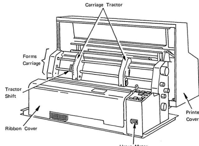
FORMS CARRIAGE
A tapeless carriage (Figure 13) transports the forms. The carriage is driven by a stepper motor under control of the printer attachment. Programmed movement of the carriage is by space and skip commands, as described later in this manual under "Programming Informationl l
• The
carriage is controlled manually by the CARRIAGE SPACE and CARRIAGE RESTORE keys. (see "Operator Pane 1 Swi tches, Keys, and Lights" under "Information for Operators").
Carriage Tractor
Shift
Usage Meter
Figure 13. Forms Carriage
The carriage has two operating speeds. The maximum speed for up to six spaces is 609 mm/sec. (24 inches/sec.) and that for over six spaces is 1397 mm/sec. (55 inches/sec.).
In place of the conventional carriage tape, the 3203-5 has a forms control buffer and a line counter.
The forms are transported by two pin-feed tractors. Two tractor
levers are provided for laterally adjusting the tractors so that the forms can be correctly positioned and tensioned. Forms varying in overall width from
89
to 452 mm (3-1/2 to 17-25/32 inches) can beinserted.
Carriage motion is monitored by photocells and any errors such as runaways or failure of the carriage to move are signaled to the attachment.
[image:28.620.145.465.230.464.2]PAPER COMPARTMENT
The paper compartment is located in the front of the printer. The unprinted forms are fed from this compartment to the carriage for printing. The paper compartment is accessible from the front of the printer by a transparent sliding door (see Figure
3).
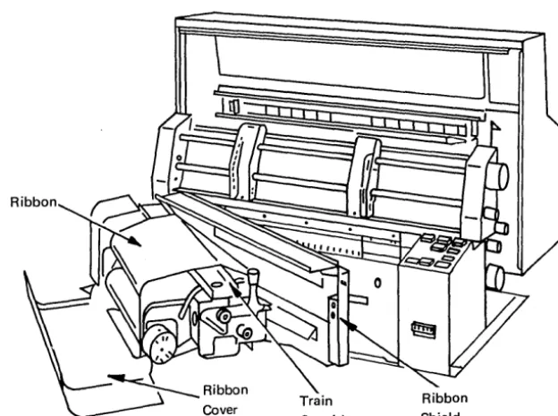
RIBBON DRIVE AND RIBBON SHIELD
The ribbon drive consists of two spools connected to two motors. The tension of the ribbon is controlled.
The ribbon shield (Figure 14) separates the forms from the ribbon to minimize soiling of the paper. It is equipped with a hammer position
indicator (see Figure 24) and with a chad shield to stop chad from fal ling into the print area.
Figure 14. Ribbon
FORMS STACKER
The forms stacker (Figure 15) is located at the back of the printer, behind the paper compartment, and accepts the printed forms. An acoustic enclosure surrounds the stacker.
The forms stacker consists of a tray-shaped grid which gradually moves down to maintain a controlled distance between the paper stacker rolls and the top of the stacked paper. The STACKER DOWN key at the back of the machine operates a power mechanism which lowers the stacker so
[image:29.623.76.388.319.551.2]that the operator can remove the printed forms. Manual adjustment is necessary before printinH starts: the tray is pushed up by hand to its uppermost position. See IAdjustment of Power-Assisted Stacker" under
III n ormation or Operators. f . f II
Rear
Paper _ _ ";---r:i~YJ
Guide
Figure] 5. Rear Unit with Forms Stacker
Stacker Components
The stacker is equipped with two sets of paper guides, one set fitted in the acoustic enclosure and a second set at the back of the stacker area. The paper guides are manually adjusted to the length of the forms. An adjustable rail is fitted onto the stacker tray to ensure that the forms settle down in the correct fanned arrangement. The correct setting of the rail and the chute, installed below the rear unit cover, encourage proper stacking.
VACUUM CLEANING SYSTEM
The vacuum cleaner (Figure 16) is located behind the left side cover of the printer. It consists of a motor-driven suction unit, a vacuum tube and nozzle, and a waste container.
Vacuum Cleaner
Cleaner
Motor
Figure 16. Vacuum Cleaning System
During printing, the vacuum cleaning system is always in operation. The nozzle positioned immediately to the left of the train cartridge continually draws paper fibers and ribbon lint from the type slugs during printing.
The nozzle is mounted on the ribbon shield. When the swing gate and ribbon shield are swung open, the nozzle is detached from the vacuum tube, and the cleaner motor is then inactive. A separate hose is kept on the storage shelf below the swing gate. When this hose is attached by hand to the vacuum tube a switch is activated and the blower
starts. The print area can then be vacuum-cleaned by hand.
[image:31.621.78.471.177.529.2]ACOUSTIC ENCLOSURE
A transparent acoustic enclosure is mounted around the forms stacker. Paper guides fitted inside at the top of the enclosure are manually adjustable to the length of the forms. When opened, the operator has free access to the forms stacker. When closed, the enclosure reduces noise during operation of the printer.
USAGE METER
The usage meter (location shown in Figure
13)
registers the operating time chargeable to the customer. The meter starts recording when the first print command is received, and stops recording when a manual space or restore operation is executed. Recording is suspended anytime the using system1s meter is stopped.MACHINE COVERS AND SAFETY
The
3203-5
should not be run with the covers open to avoid needless exposures to hazards.Some hazards such as electrical potentials and noise are less obvious than the danger from moving parts. To reduce these hazards IB~ uses recommended grounding practices for all machines and fits covers which keep noise at a level that will not damage hearing.
Information for Operators
To operate the printer, you must understand the use of the keys and switches, and the meaning of the lights. You should also know the procedure for handling the forms, the ribbon, the print cartridge, the stacker, and the vacuum cleaning system.
DLOCAL
0
UNIT
BYTE
0
EMERGENCYBURST REMOTE POWER
D
RESETD
o
ENABLE DISABLE-SVO
o
DISABLE+SVO
O+S.SV
Auxiliary Operator's Panel
Counter
~
ResetSingle
~
bd
B
Cycle On
~
B
Carriage Interlock. Restore
Carriage
I
Stacker
I I
CheckI,,~
I
CarriageSpace Restore
-, ....
B B
~
[YJ
Front Panel Rear Panel
Figure 17. Operating Keys, Lights, and Switches
Page of GA33-1529-(). Revised 9-Nov 1979 By TNL GN33-1730
AUXILIARY OPERATOR PANEL
An auxiliary operator panel (Figure 17) located on the right-hand end of the lower cabinet contains switches and lights used primarily by maintenance personnel, as follows:
EnabJe/DisabJe Switch
When this switch is in the Enable position, the printer is connected to the channel. When the switch is in the Disable position, the
printer is logically disconnected from the channel. The Disable light
turns on when the switch isin the Disable position.
Local/Remote Switch
When this switch is in the Remote position, the printer power can be turned on and off by the attaching system. When the switch is in the Local position, power to the printer can be turned on and off by the Power On/Off switch.
Byte/Burst Mode Switch
The setting of this switch determines whether the printer's channel attachment operates in byte mode (MPX channel only), or in burst mode.
Reset Switch
This momentary switch resets the channel attachment and printer, causes the printer to become not ready, and resets any error
conditions. The forms control buffer and UCS buffer are loaded with default data.
Default values are: Not ready condition AN train image loaded Allow Data Check Folding off
6
1 P iCheck conditions are reset Last Log is cleared
Forms Control Buffer loaded with channell on first line and page length of
66
Forms Control Buffer Pointer set to first line
Power OQ/Of( Switch
This switch can4be used to turn printer and channel attachment power on and off if t~~ Local/Remote switch is in the Local position. Default values: see above under Reset Switch
Note: TW§switch has to be operated for about one second to assure successflJ'l'''''power on.
I~ t.
26 3203 Model 5 Component Description apcl Operator's Guide
Unit Emergency Switch
Page of GA33-1S29-0
Revised 9 Nov 1979 By TNL GN33-1730
This switch turns off AC power to the
3203-5
and is for use only in an emergency.-SV, +SV, +8.SV Lights
These lights indicate presence of the DC voltages required by the printer controller.
Power On Light
This light indicates that
3203-5
power is on.Disable Light
This light turns on when the Enable/Disable switch is placed in the Disable position.
OPERATOR PANEL SWITCHES, KEYS, AND LIGHTS
The keys (Figure 17) allow you to put the printer in and out of operation, and to manually control the carriage. The lights inform you of printer status and of conditions requiring your attention.
START Key
Pressing the START key places the printer into the ready state, with the printer READY light on. The printer can operate only in the ready state. Pressing the START key is ineffective when any previous error condition (indicated by the INTERLOCK, CHECK, FORMS and STACKER
1 ights) has not been corrected. For convenience, another START key is located at the rear of the printer.
When the START key is pressed a check reset is also performed. If only this check reset (but not the ready state) is required, the
3203
STOP key should be held down and the START ~key pressed.
SINGLE CYCLE Key
The SINGLE CYCLE key is provided for printing single lines. Pressing
the SINGLE CYCLE key makes the printer ready until one writefcommand has been executed. After printing, the
3203-5
becomes Inot ready'.You can then print another single line by pressing the SINGLE CYCLE key again. Press START to return to normal operation.
Page of GA33-1529-0 Revised 9 Nov 1979
By TNL GN33-1730
Single cycle operation allows you to align the form properly at the beginning of a print job. Also, you can print the last lines of the final form, line by line, after end of forms has been signaled. Always make sure, however, before pressing SINGLE CYCLE, that the end of the
forms has not already risen above the print line. Otherwise the
3203-5
may print without paper and a line of print will be lost.STOP Key
When you press the STOP key, the printer completes the current
operation and stops. The printer is then in the 'not ready' state, a prerequisite for manual operations (loading forms, adjustments, and so on). Pressing the STOP key also activates the ribbon drive. For
convenience, another STOP key is located at the rear of the printer.
CARRIAGE RESTORE Key
Pressing the CARRIAGE RESTORE key causes the forms carriage to advance to the print line defined by channell in the forms control buffer. If channel 1 is not defined in the forms control buffer, no carriage movement occurs.
The CARRIAGE RESTORE key is operational only when the printer is in the 'not ready' state. If the printer is ready, press the STOP key to make CARRIAGE RESTORE effective. For convenience, another CARRIAGE RESTORE key is located at the rear of the printer.
CARRIAGE SPACE Key
Pressing the CARRIAGE SPACE key causes the form to advance one space. The CARRIAGE SPACE key is operational only when the printer is in the 'not ready' state. If the printer is ready, press the STOP key to make CARRIAGE SPACE effective.
Reset Counter Switch
Operating the reset counter switch resets the forms control buffer to address 1 without moving the forms. Address 1 of the forms control buffer should correspond to the first possible print line of the form directly under the forms perforation.
Note: Do not confuse address 1 of the forms control buffer with the address of channell code. The channell code is not necessari ly
located at buffer address 1.
When released, the switch automatically returns to the OFF position. The reset counter switch permits the forms and the counter to be synchronized before operation.
The reset counter switch is operational only when the printer is in the 'not ready' state. If the printer is ready, press the STOP key to make the reset counter switch effective.
For access to the reset counter switch, raise the top cover.
STACKER DO\VN Key (Rear)
The STACKER DOWN key at the rear of the printer allows you to lower the stacker tray.
PO\VER ON Light
The POWER ON light turns on after the 3203-5 power-on sequence has successfully completed.
INTERLOCK Light
The INTERLOCK light turns on when the printer's swing gate is open. If the interlock condition occurs when the printer is not ready, the
INTERLOCK light turns off when you close the swing gate. If the interlock condition occurs when the printer is ready, the INTERLOCK 1 ight turns off when you close the swing gate and press the START key.
FORMS Light
The FORMS light turns on when:
1. The end of the last form is about 76 mm (3 inches) below the print line, or
2. The forms have jammed, or are torn.
If the FORMS light was turned on because the end of forms was reached, it is turned off when new forms are inserted, the swing gate is closed and START is pressed. If the FORMS light was turned on by a forms jam, it is turned off when the jam is cleared and the START key is pressed. If the FORMS light turns on while the printer is not-ready, correcting the problem turns it off (without pressing' the START key).
READY Light
The READY light turns on if the following conditions are fulfilled:
1. The START key (or SINGLE CYCLE key) is pressed. 2. The STOP key is not operated.
3.
Any previous error condition is corrected (as indicated by the INTERLOCK, CHECK, FORMS, and STACKER lights).The READY light turns off if any of the following conditions occurs:
1. The STOP key is pressed.
2. The FORMS light is on because the end of forms has been reached, and the last line has been printed on the last form.
3.
The FORMS light turns on because the forms are jammed or torn.4.
The INTERLOCK light turns on.5.
The STACKER light turns on.6.
The CHECK light turns on for any reason except to indicate an equipment check only (see equipment check under "CHECK Lightll).CHECK Light
The CHECK light turns on whenever an error condition or equipment. check is detected. Unit check is indicated to the system. Detailed
information on these conditions is available in the sense bytes.
Pressing the printer START key turns off the CHECK light if no hard error is present. If a coil protect check occurred, the CHECK light cannot be turned off for at least five seconds, otherwise the hammer coils may be damaged.
If the CHECK light indicates an equipment check only and the READY light is on, the CHECK light is turned off by any command other than
d I I
no-operation an sense.
STACKER Light
The STACKER light turns on when the stacker is full. It may also turn on if a stacker jam or other stacking error occurs.
The STACKER light turns off when the stacker has been emptied or the stacking error has been corrected and the START key is pressed.
MANUAL CONTROLS
Use the manual controls (Figure 18) to adjust the position of the forms in relation to the carriage and the hammer unit, and to make adjustments for print quality.
Figure 18. Manual Controls
Forms Advance Knob
Forms Advance Knob
Horizontal Print Adjustment Knob
Vertical Registration Knob
"-~"---~ Density Knob
Forms Thickness
~---+-Knob
Turn the forms advance knob to move the forms vertically. You can use this knob only when the printer is in the 'not ready' state. Do not attempt to force the knob.
Vertical Print Registration Knob
The vertical print registration knob allows a fine setting of the forms at the print line. The print line can be adjusted through approximately 3 mm (0.12 inch) during printing.
Horizontal Print Adjustment Knob
Turn the horizontal print adjustment knob for a fine adjustment of the forms in a lateral direction. A range of 12.7 mm (0.5 inch) is
available.
The setting of the horizontal print adjustment knob can be seen from the three rings on the adjustment shaft (Figure 19). When the middle ring is just visible to the left of the housing, the midpoint of adjustment is reached. The other two rings show the limits of left and right adjustment.
Figure 19. Fine Adjustment of Forms in Horizontal Direction
Print Density Knob
Use the print density knob to regulate the impact energy appl ied to the paper. The knob is marked with a sca 1 e from "A" through "0". The pos it i on
"A"
gives the hi ghes t pr i nt dens i ty recommended for th i ck forms, and the position"0"
gives the lowest print density~recommended for thin forms. Refer also to the label on the ribbon cover.
The print density knob is also used to compensate for various ribbon conditions. Turn the knob towards
"0"
when the ribbon is new, towards"A"
when the ribbon is old.CAUTION
Do not leave the knob at "A" after a new ribbon has been mounted. A permanent "A" setting keeps hammer impact needlessly high, thus causing early wear of the ribbon.
Forms Thickness Knob
The forms thickness knob allows you to adjust the gap between the print train and the hammers. The knob is marked from 1 through
6.
A low setting is recommended for a single part form and a high setting for a multi-part form. Poor adjustment may cause the printedcharacters to be light at top or bottom. The settings are also shown on the ribbon cover label.
Paper Brake Adjustment Lever
The paper brake adjustment lever (Figure 20) allows you to adjust the paper drag according to the weight of the forms. The adjustment lever has three positions (1, 2, and
4),
corresponding to the number of parts to the forms (see the label on the ribbon cover). For asingle-part form, for example, select position 1. Special conditions or a particular type of form may make it advisable to choose a
non-standard setting. Wrong adjustment of the paper brake may cause
misregistration. .
Figure 20. Paper Brake Adjustment Lever
OPERATING PROCEDURES
Forms Loading
There are two procedures for forms loading: one for initial loading into the empty printer, the other for reloading after an end-of-forms condition or when changing to a different type of forms. The principle
is similar in both cases but the objectives are slightly different.
During initial forms loading, the aim is to synchronize and align the forms in the printer. When replenishing the forms supply during a job, you must retain this synchronism and alignment.
Initial Loading
1. Raise the printer cover. Pull the swing gate locking lever (Figure 21) toward you and open the swing gate.
Note: Open the train gate only while the printer is in the
not-ready state. Opening the gate while the printer is ready may cause unpredictable results, such as lost print lines and check conditions.
Swing Gate Figure 21. Opening the Swing Gate
2. Position the left-hand tractor immediately to the left of the first print hammer. The tractor slides freely when you lift the tractor tab (Figure 22).
~ _ _ _ _ _ _ --t-Tractor Tab
Figure 22. Positioning a Tractor
3.
Lift up the covers of both tractors unti 1 they remain open. Placethe forms into the forms compartment, reach over the lower structure and pull up the forms.
4.
Place the left-hand margin of the first sheet over the feed pins of the left-hand. tractor and close the tractor cover (Figure 23). [image:44.621.141.560.91.709.2]Tractor Cover
Figure 23. Closing a Tractor Cover
5.
Slide the other tractor until its feed pins fit into the holes of the sheett then close the tractor cover. The form should be smoothwithout being tightly stretched. Set the vertical print
registration knob to position 0, and turn the horizontal print adjustment knob until the middle ring (see Figure 19) on the shaft
is just visible to the left of the housing.
6.
Close the ribbon shield. Lift both tractor tabs and align the forms horizontally against the hammer position indicator scale (Figure 24) according to your instructions for the job. (Forpreprinted forms, a given hammer position must normally be aligned with a particular point on the form.) Turn the horizontal print adjustment knob (see Figure 18) to move the forms exactly into position.
Figure 24. Hammer Position Indicator
7. Open the ribbon shield. Position the form vertically by turning
the forms advance knob (see Figure 18) until the perforation
between the first and second sheets is aligned with the top of the scribed line on the printer (Figures 25 and 26). Set the paper brake to position 1, 2, or
4,
depending on the number of parts to the forms. (With some forms, results can be improved by trying a different setting.) Close the swing gate.Scribed Line
Figure 25. Printing Area
Note: The second sheet is now correctly aligned for printing. The first sheet is a dummy leader, especially when the forms are sequence-numbered or have multiple parts.
8.
Operate the counter reset switch. The form is now initially synchronized, that is, set to the first printable line.9.
Align the forms stock in the compartment so that the forms lead straight up, then close the sl iding door. Adjust the stacker as described in "Stacker Adjustment " . If the stacker is setcorrectly, proceed to "Starting the First Print Job".
...
, I
Top of scribed line
First Sheet
Second Sheet
Figure 26. Initial Vertical Alignment of Forms
Forms Unloading
1. Press the printer STOP key.
F'I
Print Hammers
2. If the end-of-forms switch has operated, the FORMS light turns on but printing continues until the printer attachment detects the end-of-sheet code in the forms control buffer. Thus the last form
is completely printed. Go to step
3.
If the end of forms has not been reached, go to step4.
3.
Press CARRIAGE RESTORE to unload forms. Go to step 7.4.
Move the forms upward until the end of the last printed sheet isjust above the tractors. (Use CARRIAGE RESTORE or CARRIAGE SPACE,
or both keys, depending on length of forms.)
5.
Tear off the forms below the last printed sheet.6.
Press CARRIAGE SPACE to unload forms. 7. Remove the job from the stacker.Forms Reloading
The procedure for reloading depends on whether the same type of form or a different type of form is needed.
Note: Open the train gate only while the printer is in the not-ready state. Opening the gate while the printer is ready may cause
unpredictable results, such as lost print lines and check conditions
To reload with identical forms, raise the printer cover, open the swing gate and open both tractor covers. Place new forms over the previous forms so that the perforations match exactly (Figure 27).
This overlapping ensures that synchronism remains unchanged. Do not
move any switches or knobs. Close the tractor covers and the swing gate. Close the printer cover, and press the printer START key to continue.
[image:47.624.55.550.292.657.2]~T---..l.~L~:::::::;::::::- ~
AlignFigure 27. Positioning New Forms
To reload with a different type of forms, run out the old forms by
pressing the CARRIAGE RESTORE key several times. Then proceed as
descr i bed under "I nit i a 1 Load i ngl l
38 3203 Model 5 Component Description and Operator's Guide
Power-Assisted Forms Stacker Stacker Parts
1(,.
The
o
•
•
•
adjustable parts Stacker tray Paper rail Paper guides Stacker chute
Rear Paper Guide
of the power-assisted stacker (Figure 28) are:
Front Paper Guide Stacker Chute
[image:48.615.88.571.143.628.2]Stacker Tray
Figure 28. Adjustable Stacker Parts
Stacker Tray: This is a horizontal grid which holds the printed forms. You raise the tray by hand (Figure 29) and lower the tray by pressing the STACKER DOWN key. During printing, the tray moves down
automatically as the paper pi le grows. The movement is controlled by a sensing device (Figure 30), located on both sides of the stacker
housing.
CAUTION
[image:49.623.54.553.157.379.2]Raise the stacker tray only when the printer READY light is off. If the tray is raised during the printer ready state, the beams of the sensing device may be broken, causing an automatic downward movement of the tray.
Figure 29. Raising the Stacker Tray
Light Beam Photocell
--
-Stacked
t 4 - - - - t - + - -Forms
"-iiiilijiiiiiiiiiill.
/
Stacker Tray
Figure 30. Paper Pile Sensing Device
Paper Rail: This is a bar mounted over the stacker tray to improve stacking.
1. Upward Adjustment. Raise the paper rail (Figure 31) and engage the notches in the holding rod.
2. Downward Adjustment. Disengage the rai 1 from the holding rod and lower the rai 1 into the stacker tray.
[image:49.623.71.528.392.667.2]Holding Rod
Figure 31. Hinged Paper Rail (Up Position)
Paper Guides: The paper guides (front and rear) are two vertical grids which guide the printed forms onto the stacker tray. The guides (see Figure 28) are suspended from pairs of numbered holes which you select according to the length of the forms.
Stacker Chute: This is a metal plate mounted in the housing over the
stacker tray. The chute helps to improve stacking, particularly of
single forms. It can be set to three positions; up, middle, and down (Figure 32).
UP POSITION
[image:51.618.26.286.61.713.2]DOWN POSITION
Figure 32. Stacker Chute
Adjustment of Power-Assisted Stacker
Set the adjustable parts of the stacker according to the length and stiffness of the forms as described in the following text.
Note: It may be possible to improve results by varying these settings on a basis of trial and error.
For Paper Forms up to
356
mm (14 Inches) Long:1. Set the front and rear paper guides to the length of the forms. The minimum possible setting is 203 mm
(8
inches), even if the forms are shorter.2. Push the stacker tray to its top position.
3.
Set the paper rail and chute to the levels shown in Figure33.
Settings Forms
Paper Rail Chute
One-part Down Down Two to four parts Middle Middle More than four parts Up Up
Note: It may be possible to improve results by varying
these settings on a basis of trial and error.
Figure 33. Recommended Settings of Paper Rail and Chute
For Paper Forms Over 356 mm (14 Inches) Long:
1. Remove the rear paper guide from inside the acoustic enclosure and slide it into the tubes in the stacker tray. This extends the stacker tray to support the longer forms.
2. Press STACKER DOWN until the stacker tray reaches the middle
position. If stacking is untidy, lower the tray until it improves.
3.
Set the paper rail and chute to the levels shown in Figure33.
4.
Leave the acoustic enclosure open during printing.For Card Stock and Extra-Stiff Forms:
1. Set the front and rear paper guides to the length between the major folds of the card stock.
2. Press STACKER DOWN until the stacker tray reaches its lowest position.
3.
Set the paper rail to the down position.4.
Set the stacker chute to the up position.When a job starts, always guide the first few forms evenly onto the stacker tray by hand.
Note: If the relative humidity is more than
65%
or less than 20% you may have to give your full attention to the stacking.Starting the First Pri