Systems Reference Library
IBM 1231, 1232 Optical Mark Page Readers
File No. 1231 -03 Form A21-9012-3
This publication describes the functions, controls, principles of operation, data flow, and programming for the IB~1 1231 and 1232 Uptical ~1ark Page Readers. Special features available are explained. Also included is a section on the IBM 534 Model 3
This publication, form A21-9012-3, replaces and obsoletes form A21-9012-2. Information from technical newsletter N21-OO23 is included. Changes to text are indicated by a vertical line to the left of the column. Changes to illustrations are indicated by a
bullet (.) to the left of the figure title.
Copies of this and other IBM publications can be obtained through
IBM Branch Offices. Address comments concerning the content
of this publication to:
IBM, Product Publications Department. Rochester. Minn. 55901.
IBM 1231 and 1232 Optical Mark
Page. Readers. . . .. 5
Data Sheet. . . .. 8
Data Sheet Terminology. . . . . . .. 8
Marking the Data Sheet ... , 8
Principles of Operation. . . .. 10
Document Path. . . . .. 10
Feed Hopper. . . . . . . .. ... 10
Feed and Transport Mechanism . . . 10
Selector Station and Stackers ... , 11
Reading ... 12
Read Unit ... 12
Mark Recognition and Discrimination ... 12
Data Flow. . . . . . . . . . .. 13
IBM 1231 Data Flow ... 13
IBM 1231 Message Format ... 14
IBM 1232 Data Flow. . . . .. 14
IBM 1232 Message Format. ... 15
IBM 1232/534 Synchronization Check. . ... 15
Field Checking. . . . . . . . . . . .. 16
Alphabetic Coding. . . . . . .. 19
Controls. . . . . . . . . .. 19
Keys and Switches. . . . . . . . . .. 20
Lights ... 21
Programming. . . .. 22
Program Control Sheet. . . . . . . . . . .. 22
On-Line Systems Programming. . . . . . . . . .. 24
On-Line Program Instructions. . . . . . . . . 26
Contents
Operating Procedures... 27IBM 1232 Setup. . . . . . . .. 27
IBM 534 Setup. . . . . . . .. 27
IBM 1231 Setup. . . . . . . .. 27
Restart Procedures ... 28
Special Features . ... 31
Master Mark Feature ... 31
Segmented Word Feature ... 31
Special Card Features ... 31
Multiple Spread-Card Feature ... 32
Unit Record Card Feature ... 34
IBM 534 Model 3 Card Punch ... 38
Punch Controls. . . . . . . . .. 38
Programming. . . . . . . . . .. 38
Throughput Factors... . . . .. 40
1231 Throughput ... , .. 40
1232/534 Throughput. ... , 40
Document Design and Specifications. . . .. 42
Specifications ... 42
Paper Requirements ... , 42
Burst qontinuous Forms. . . . . . . . . . .. 42
Ink Requirements ... 44
Document Format Requirements ... 44
Printing Requirements. . . . 44
Design Guides. . . . . . . . .. 46
Document Gage. . . . . . . . . . . .. 49
IRM 1231 with IBM 1401 Data Processing System
IBM 1231 and 1232 Optical Mark Page Readers
During the past several years many changes and ad-vances have been made in the field of data processing. Computer access times have diminished from many milliseconds to a few microseconds. Printing speeds have risen from 100 lines a minute to well over 1000 lines a minute. Programming systems have become problem oriented, easier and cheaper to use.
Although these significant advances have taken place in the processing and output areas of data processing, no significant improvements have been made in the methods by which source data is recorded and entered into these systems.
The IBM 1231 and 1232 Optical Mark Page Readers represent a breakthrough in the area of source recording and data entry. They provide a facility for recording the data at its source, in a form that can be converted directly into data processing language.
The IBM Optical Mark Page Readers read positional marks made by an ordinary lead pencil on paper documents. The positional marks are converted into a machine-usable form by the 1231 and entered directly into a data processing system; or the marks are read and the information punched into cards by the 1232. Documents are read in the 1231 and the 1232 at a maximum rate of 2000 sheets per hour. Throughput for the 1232 depends upon the format of the data sheet, the number of card columns to be punched, and the number of cards per data sheet. The 1231 throughput depends on computer programming, the feed mode (Continuous or On-Demand), and the method of group-ing the data on the data sheet. (When identification data and detail data are interspersed and read into 1231 storage, more program steps are needed to separate the data in the computer.)
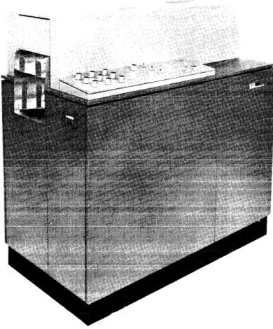
The 1231 (Figure 1), therefore, acts as an on-line input device to data processing systems, such as, IBM 1401, IBM 1440, and IBM 1460.
The 1231 is a fully-buffered machine that operates at an average document cycle of 1730ms in continuous feed mode. Variations in data-sheet feeding can cause a document cycle to be as short as 1585ms. The maximum time to transfer data from the 1231 buffered storage to the comput~r is 7.2ms. Therefore, 1585ms minus 7.2ms, or 1577ms can be safely used as processing time by the computer. Thus, 1231 sub-routines can be inserted into routines of other applications.
The IBM 1232, when operating with an IBM 534
---Figure 1. IBM 1231 Optical Mark Page Reader
Model 3 Card Punch, can convert data into punched cards directly from the source documents. Conversion speed can be as high as 64,000 characters per hour, or
800 fully-punched cards per hour.
Optical Mark Page Readers are ideally suited for applications such as: order entry, payroll, accounts payable, inventory control, sales analysis, and general ledger work.
The 8 1/2" x 11" data sheet is a versatile document, adaptable to many applications. One of its uses may be as an order entry form (Figure 2). Insurance com-panies could use the data sheet in areas such as; debit route accounting, policy applications, or policy rating (Figure 3). Medical centers may find the data sheet and its subsequent processing convenient for patient billing, clinical analysis, or medical histories. Other
area~ of business such as; marketing research and survey companies, schools and stock brokers will also find appli-cations for the data sheet and its processing.
By means of stored program controls, the IBM 1231 and the IBM 1232 can:
• Control specific data to be stored.
• Control data that is to be repetitively punched into cards.
• Identify the end of a field.
[image:5.612.333.528.128.363.2]0\ "rj
oq. ~
n
~
~
a
'E. n 0
"1
0-n "1
~ t:I
~
tj
~
;
~ ::r
a·
CUSTOMER NAME
SALESMAN
DATE
Make your IIICIIb wIth a block lead pencil. EI'CIM completely
ABC COMPANY ORDER FORM
CU~:TOMER NUMBER
SALESMAN NUMBER
ITEM NO. ITEM UIIT SIZE
I
-ITEM
ITEM
ITEM
ITEM 5
I I 0, n ! ' ' ' , , '
any mariti )'OUwlth 10 cha,... ITEM 6
QUUTITY
Mak41 )'OUr malb wIth a black lead pencil. Era .. completely any malb changed.
DATE
~,~"
ITEMBond Sow Modll A Bond Saw Modll B Bond Saw Modll C Cire. Sow Modll A Cire. Saw Model B Cire. Sow Modll C PI)I't. Drill Model A P')I't. Drill Model B Ol'ill (Floor! Modll A OIrlll (Floor) Model B SIJbrl Saw Modll A S'Jbrl Saw Modll B S'Jbre Saw Modll C RIJdlal Arm Saw Mod. A Rlxlial Arm Saw Mod. B RIJdial Arm Saw Mod. C Elle. Grindlr Modll A Elle. Grindlr Modll B Elle. Grinder Mode I C Oile Sander BOlli Sandlr Modll A Bltll Sandlr Modll B PI)Wlr Haekaaw Mod. A Powlr Haekaow Mod. B Pc_r Hacklaw Mod. C Elle. HldQltrimmer A Elle. HedQltrimmer B LClthe Model A Lellhl Model B Lelthl Modll C Jointer Planer Mtltder Planer Modi I A M'~ld .. PI01IIr Modll B
XYZ COMPANY
~ ~
~
~ 1:/.lI
I
~.[
~
'E. ~.g'
t:;j DI ; 1:/.l ::r' g fitMake your mark. wllfl a black lead pencil.
DATE 0' ""'-ICY 1
~LNIJij[ (Print
ANY LIFE INSURANCE COMPANY
INDUSTRIAL APPLICATION
EJ'IIIe completely any marks~.
P o
L
::6:: ·-r- ::j:: --j-- ::,i:: I =:i:= ::j:: ::j:: ::j:: .
-
-(Nt:C'IAS'nWI£J---llIob1lL£-INlY,-,-iftt Ie T C y
N
S. Nt. 01 'wtn IIT.T£)
I:":
(iJ;MT:ARr.::: ::
==.:= =:i== ::,:: ::j:: ::~:: ~ ::j:: ::i:= --j-- --j----j--..
wW~ ji~1j,
B E R
Wlllot i, rour
I i
:":u
:.-::t~~_~~_:..~~~-!::.--~,;~__
I_~.;;·· .. ______ n u n lit •... SURANCE COMPANY.?
II ~'(lIrw.I---,uLLNAME)
[<K
IF YES, WHICH?
1.-10
~lICY ~PPLlCP '9"
(0) PLAN
'-100
~:~:
IUO ,:~
~:~~
'-;00
~-!~
~~
':~
IQ til oetONfl,*, JOi .1tI •• __ 1M'", of worll. ,..,or ... .
.-iXIO
~-!!
,:~~
~~: "~ "!~
'!!!:!-~ IPKIP'Y C*aACK 15. H ... , . 1ft tie , . •• fl¥o ,..,. ... "'Ior for . . . riM.
.. 1 . . . IIMettt ... t, ... c _ c . I •• vilVl.'
. . . 'NO . . . ' . . . ; ... , . . . t
...
,.,...
,
...
,
If job titl • . , , . . . . , . . . . e .... "' . . i. iItMr.t . . . 10 •• o-tioft.IO .... e.
I 1'1 "aw. , ... , ,..,..nl tI.f ••• or I.,."",., 0' tI ... :· onbCiQ.
(o)Mtiti. (b)N... te' . . . . . " ...
Pr ... EM..,...
~
" PR(MlQ!r.em.u
12. CLASlIFI~J..Q!
-in
-.0-If,.. • ..,1 . . . . "ok.
Il Walll" 'lle t ... 'Iv. , . . . Mi •• ,OIl .... 11 tleoli,,". ,...,....tI.
•• ".,M • ,..ie, .tt •• , ... .,,11 •• f., b, ... , . , •• Iler . . . ,.."
-YD
-iiD-I" ••••• , ... ell..
II. o..."Ne ••• , .. itl. I . . . t • • • llllo"
ST~ RA-ririe. R.¥!iI'5
Of_
~C'" 0111 lACk dI.tricto"lc.i . . . tI, vii'.
::~:: TINS • UIIITIH~ • •
~
I:!:
::~:::~:
:;;::
::!:: ::~:: ::!:: :!~: -!!~: ~:W E 0 --- ---I ----I ,,-•
I 0 I I
G ,---- --- --- "~,, H O I I . . . •
::,:: ::,:: I'EET INCHES POUNDS --,-- ::,::
..,AT •
--0-- --r- --r- --j-- ::~:: C. ::j:: ::i:: ::t:: ::it:: 19. "EPORT OF FIELD REPiiEItNTATIYE
How. l'IN ch'ck", ... o"lIc.tloll to ... ell ... o"d CIU ••• i . . . Oft • • • , . . , :::::ftI :::::Il10
Do,.ucortlf' ... t.IIII'.' ... ioftOOfl •• III . . . I.RE~
OF NLD IItEPftUOfTATIYI iI it ., . . . tI •• ".et n" .f
iI'_.tI ... .". ... II.".I •• " ... '
T -- - '''co '''co --- '''co u",n '''- 1 . _ T ... 0' ...., U_st:NTaTIV[
20. I h •• b, r . . . " ' 'hot .ny DIYIDENDS pa,.w. .-d.r tho ,~ic:, ON .... fer .... " . , . . . •• 'M ,., . . . f .... '0 UII ADDITtONl TO THE .... IN..-o UNTIL ANO UNLESS ANY OTHER OPTtON SHALL. S[LECTED IN ACCOItOANCE WITH THE Tilltill OF THE POLICY.
The fOflltoifti .t.I ... 1I . . d aM.., •• ro trll' . . tI co • • , • • • tI it I ... ntl .111 •• : (I) ~ . . . t . _ t • • tI ... ,. .... , , ... Ite b . . . f
.he Clfthact of "'lIrGftCI If OM ,. i .... tI\ (2l no .,.", or ... , at..., ,., ... co" 'M Prooitl ... Of . . . , . , 1M C..., .... , ... ..
bohalf o' 'h. eo . . . . , (.) t. ",ok' • • • tllf, or til ... on, elft'root . f 111'._, or . . . . ~ 'l1li eo.,III, .. , •• ki., ... , '"" . . . . . r . . ,.ctl" . . . . , ... flt. _ .... .., ,.'ic, i . . . UfttI.r; (5) 'N COIII . . . ,.III ItlClN' ... lI.blll., " r . . . . 11 ., HIlI . . . tio .. oao., • • • • • , be pro'!i •• d i . . . c:..itl .... IR ... lp.'I ••• o" . . . in" . . . ."..ooll ... "III." .. e' ... tI.ntltlll. ,.n'irst pr .... l\IM . . . ,oid ••• IM COM, ... ,.
AnMu .. ~ ,oid I" .ch . . . . 011 .ecCMIII' ., .t __________________________________ tN. ___________ ell, . f _____ . ___________ _ F" ... It IIr.",1uII! • ____________________ . __ SI, ••• ur.O' ""Iie • • ________________________________ . ___ _
, . . _ t hili fi, •• pro.-""" SIo"."r. of Wit ... _. _____ . ___________________________________ ., _____ _
'oiif'" i 'oiif'"
-ANY INSURANCE COMP-ANY ROUTE LIST
COLLECTION WEEK 935
I
DAY 2I
DEBIT 1152I'INANCIAL C!IITIFICATION "~,,
D
AGENT'S
SlGNATURE ___________________________________________ _
E B
I
T
PREMIUM NUMBER OF PAYMENTS 2034 296 1 5933 2 296
2035 295 1 5933 295
2038 5930 5 246
2043 10 1 5934 10
2045 337 1 5934 337
2150 530 5934 265
2157 362 5934 362
2165 110 5933 2 110
2180 5935 145
2182 105 593S 105
2185 5935 142
2190 5932 3 89
2195 5932 3 225
2197 5932 3 70
2198 450 5933 2 225
2203 5929 6 120
2209 5934 30
2210 120 5933 2 120 _. __ . _
-2213 105 5933 2 105
2214 197 5934 197
2215 30 5939 4 30
2216 5934 120
2218 125 1 5934 125
2220 50 1 5934 50
2225 120 1 5934 120
2230 130 1 5940 5 130
2240 5941 6 49
2241 5933 2 10
2250 255 1 5933 2 2SS
2255 75> I 5934 75
2255 150 1 5934 150 ::~'t~'!:::::
2260 336 1 5934 336
2262 76 1 5934 1 1 1 1 76 I
---2262 282 1 5934 1 .1 1 1 282 I '''co '''co '''co 2275 5934 I 1 I I _ I 165 I '"'' '''co ,,,,, '''co '''co
Make your I'IICIrks ytllfl a black lead pencil. &ale completely any marks changed.
--~-- . ~
'''''1=
A 1231/1232 can be programmed to recognize each part (field) of a data sheet on an individual basis. Each field can then be checked for the various conditions under which a document can be selected.
A Master Mark special feature provides group identi-fication when· several data sheets are to be processed as a group.
Data
Sheet
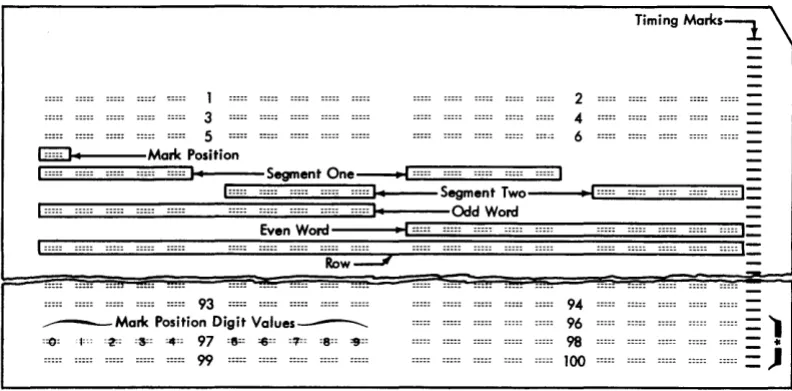
The document used as input to the Optical Mark Page Readers is an 8 1/2" x 11" sheet of paper called a "data sheet". The data sheet contains a maximum of one thousand mark positions. The mark positions are ar-ranged in as many as fifty rows, each row containing a maximum of twenty mark positions.
Each row is divided into two groups of ten mark positions each. The ten mark positions are called "words". Each word is divided into two groups of five mark positions called "segments". Consequently, each data sheet can have a maximum of 50 rows, 100 words, and 200 segments. A data sheet normally contains five rows per inch, but may have less.
Timing marks are printed along the right-hand edge of each data sheet. These marks are used to synchronize the motion of the document with the various units of the reader. Each word on the data sheet has an associ-ated timing mark.
Words within each row of the data sheet are divided
into two groups: odd-numbered words and
even-numbered words. Odd words are on the left, even words on the right. The timing mark for an odd-numbered word is .636" above the mark positions of the word; the timing mark for an even-numbered word is .536" above the mark positions of the word.
Whenever a new data sheet is to be designed, three standard layout forms are available for use as design guides. Form X20-8043 is designed with five rows per vertical inch; Form X20-8044 is designed with four rows per inch; and Form X20-8045 is designed with three rows per inch. Any combination of these forms may be used as long as the timing mark relationship to the rows is maintained, and the rows are never printed closer
I
than the minimum spacing of .200". Two timing marks should be printed for every row of words as these timing marks are used to trigger the read head activity from odd-word to even-word to odd-word, etc.
Input documents must adhere to specific dimensions and tolerances. When a new document is designed or ordered, document layout, paper, and ink requirements should be reviewed. Before large quantities of documents are ordered, a sample of the document should be sent to the nearest IBM Branch Office for review.
8
Data Sheet Terminology
Timing Mark: Rectangular marks preprinted on the data sheet in non-reflective ink. The timing mark is used to synchronize the motion of the document with the various units of the 1231/1232. Timing marks are located on the right-hand side of the data sheet (Figure 4).
Mark Positions: Areas printed in reflective ink that designate where marks are to be placed. A non-reflective mark in this area is read as a word or bit.
Words: Ten mark positions of a row. Words on the left half of the data sheet are odd words; words on the right half of the data sheet are even words.
Segments: Mark positions 0 through 4, or 5 through 9 of any word.
Non-Reflective Inks: A type of ink that is sensed by the 1231/1232. Usually, timing marks are the only non-reflective printing on the data sheet. The recom-mended non-reflective ink is black. See Ink Require-ments.
Reflective Inks: A type of ink not sensed by the 1231/1232. Reflective inks are used for headings, data sheet instructions~ mark position outlines and any other data that is not to be read.
Marking The Data Sheet
Marks that are to be read by an IBM 1231/1232 must be dark enough for positive machine-reading, yet erase easily and completely. For these reasons, a number 2 pencil is recommended.
Marks made with a number 1 pencil, or an IBM Electrographic pencil
*,
are difficult to erase; even after an erasure is made, a residue remains that could be read as a mark by the machine.Erasures should always be made carefully and com-pletely. Any incomplete erasure coulJ oe read as a mark.
\Vhen response positions are marked, the mark should be made the full length of the mark position, and should fiiI at ieast two-thirds of the space between the top and bottom of the guide lines. A mark that extends no more than 1/16" past the ends of the response position is acceptable in all but the last even-word position (next to the timing marks). In this position, a mark must not extend beyond the right end of the guide lines or it could be read as a timing mark. This would result in erroneous reading of the rest of the data sheet.
1 3 5
2 4 6
Timing Marks~
_LG31;;;::;;;::...}oI----Mark Position
[1:~::~::::~~~~I:~:::~::JI~I-~::=SegmentOne~~:~::~::~::~::~:~:::~::~:~:::~:~:::~::~I
~,:~::~::;;~~~~~~~::~'~:::~::ES:~:::~:~::~:::ES:~::~::~::~::~::~:::::::~S~;~:~o---
••~I~:::~::::~~~:E~:::~::J:II::
Even Word I I :::::I:::::
Row=--.;/
~ ::::::::::r
93
____ Malit Position Digit Values___..
:=0: j:oo :~: :3=: :4:: 97 :8=: =6:: :1!:: :8:: =9::
99
94 96 98
100
*
These six control timing malits are used for counter read out controls in the IBM 1230.Figure 4. Data Sheet Format
:::::. :::::.
[image:9.613.77.473.60.255.2]Principles Of Operation
The IBM Optical Mark Page Readers use sonic delay lines for storing controls and data. Controls are marked on the regular data sheet and entered into storage during the program load cycle. This data sheet is referred to as a program control sheet.
As data sheets are read, data is stored in the delay lines according to instructions from the program control sheet. Each word or segment to be stored must be pro-grammed for entry into storage.
When a data sheet passes under the photo-electric read head, each word or segment is tested (according to preset switch settings) for conditions, such as; no-mark, multi-no-mark, or other-than-one, Any word or segment that does not pass the requirements of these switch settings causes the data sheet to be routed to the select stacker.
Storage data is available for readout to either a data processing system or to an IBM 534 Model 3 Card Punch. The cards punched in a 534 operation can be used as input to either a data processing system or a unit record machine.
Document Path
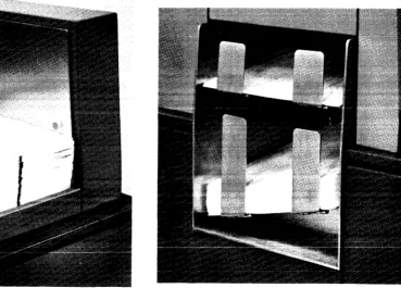
The data sheet begins its movement through the Optical Mark Page Reader when it is fed from the hopper. The document then passes under a read head; is transported through the transport area, past a selection station, and on into one of the two gravity stackers (Figure 5).
Feed Hopper
Data sheets are placed in the hopper (Figure 6) with the side to be read facing up; the top edge of the data sheet positioned to feed first. Data sheets feed from the top of the stack. The platform on which the documents are held raises automatically to maintain proper feeding. Whenever documents are added to the hopper, document fpprllnu TYlll<!t hp rll<!rnntlnllprl ~nrl thp nbtfnrTYl InlATPrprl
---0 --- -- --- ---- ----
r - ..
--to accommodate the additional supply of documents. If the stop key is pressed or any emergency stop switch activity occurs, the document platform drops immed-iately. The stop key stops only the feeding of the docu-ments. An emergency stop (jam, misfeed, timing mark check, etc.) halts the feed rolls, as well as document feeding.The capacity of the hopper is approximately 600 documents. When documents are processed at the rate of 2,000 per hour, the hopper capacity is great enough for 18 minutes of continuous operation without operator attention. If feeding is attempted and for some reason,
10
such as an empty hopper, a document is not fed within five seconds, the entire feed unit stops operating and the hopper platform drops.
Feed and Transport Mechanism
The feed unit of an Optical Mark Page Reader contains a set of four picker belts, two restraint belts, and a separator roll. The transport area contains the feed rolls. As the feed rolls move a document through the transport area, the document passes a selector station and moves on into either the normal or select stacker.
A depression of the reset key brings documents up to the feeding level and starts feed roll and restraint belt activity. When the start key is pressed, picker belt and drive roll activity starts. Picker belts and the separator roll are operated by the picker belt clutch. The picker belts ride on top of the stack of documents in the hopper, and move documents into the separator station.
At the separator station, a drive roller acts upon the top document to move it forward, while restraint belts move the balance of the documents backward. This
. 1 · , . • _ _ _ _ •• _ _ _ r 1 __
creales a snearIng acuun, causllig separaUUIl U1
UUCU-ments. The top document feeds, and the lower documents are restrained. The restraint belts move at a slower speed and have a lesser effect on documents than the drive roller. Therefore, whenever both the drive roller and the restraint belts act upon the same document, the document continues to move forward.
The first set of feed rolls is located about one and one-half inches ahead of the leading edges of the documents in the hopper. A document sensing device, just under the first top roll, senses the presence of documents. As documents pass, they are recognized by this sensing device, causing the picker belts and drive roll to stop. When the trailing edge of the document passes the sensing device, circuits are activated which cause another feed cycle. Consequently, if the feed mode switch (1231) is set for continuous feeding, documents feed approxi-mately one and one-half inches apart.
When the 1232 is operating with the IBM 534 Model
3 Card Punch, documents feed as just described, but
are controlled by the program card in the 534. The picker belts do not operate until two conditions are satisfied: (1) the 534 has issued a feed call, and (2) the previous document has passed the document sensing device in the 1232.
com-Select Stacker
Stacker Selector
Jam Bar
Read Head
Double Separator Picker Sheet Wheel Belt
Detection
Hopper Control Valve
~~8~~
~~~I
StackerFigure 5. Document Path
pleted. Drive rolls beyond the read station accelerate the document to ensure proper stacking.
Selector Station and Stackers
An Optical Mark Page Reader has two stackers, Normal and Select, into which it can direct documents (Figure 7).
Figure 6. Feed Hopper
Restraint
Belts
Air Cylinder - - - + 1 1 1
Document
Platform
The normal stacker holds about 600 documents. The select stacker, which is just above the normal stacker, holds about 50 documents. Both stackers are equipped with full-stacker switches that stop document feeding when either stacker is filled.
As soon as a document passes the read station, the reader examines its logic and machine controls to deter-mine into which stacker the document will be directed. Documents always enter the normal stacker unless
con-Figure 7. Stacker
[image:11.613.73.573.58.288.2] [image:11.613.79.318.432.707.2] [image:11.613.189.558.445.710.2]trolled to enter the select stacker. If a document is to be selected, a selector guide in the selector station deflects the document into the select stacker.
The processing unit can also control the direction of a document into the select stacker if a 1231 is being used. After the document has been read, the processing unit has 50 ms in which to analyze the data and give the select instruction.
Reading
"Reading" is a tcrm applicd to the recognition of data, and its conversion into machine-usable language. The IBM Optical Mark Page Reader recognizes data by means of changes in current at the read head.
Read Unit
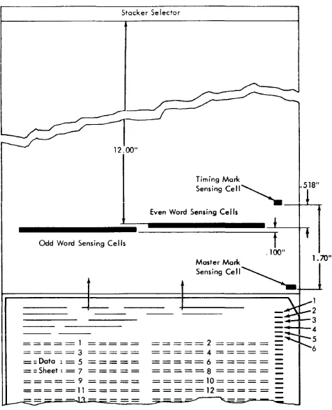
The read unit of a fully-equipped Optical ~Iark Page Reader contains 22 photovoltaic cells. Twenty of these cells are used for reading data from the document, one is used for reading the timing marks, and one is used for recognition of a master mark (special feature).
Each photocell has an associated light source and light-limiting aperture. As documents pass under the read unit, light is directed onto the paper from these individual lamps, and reflects onto the exposed surface of their associated photoceils. The intensity of the iight striking the photocell is less when reflected from a marked position than when reflected from an unmarked position. Photocells respond to light by producing current in measurable values; the more light striking a cell, the higher the current value. The Optical Mark Page Reader recognizes a current value substantially lower than normal as an indication that a mark is directly under the photocell. In order to assure that the Optical Mark Page Reader is reading valid marks only, outputs from the photocell are sampled only when mark positions on the document are properly positioned under the read unit (Figure 8).
The timing marks are read by the timing-mark photo-cell. When the first timing mark is read, the read cells for the first word are activated. As the data sheet moves on, the second timing mark is recognized and the second word is read. The timing marks synchronize the read cells with the word to be read.
i1 .. S the data sheet moves through the read station,
the timing marks cause the read cells to "flip-flop" from odd word to even word to odd word, etc. Because of the vital functions performed by the timing marks, extraneous marks must not be marked or printed in the timing-mark area.
Under control of the timing marks, words are read from left to right, from top to bottom, row by row. Two timing marks are associated with each row (one for each word). The first timing mark (upper) activates
12
Stacker Selector
Odd Word Sensing Cells
= = = = = 1 = = = = = = = = = = 3 = = = = = = = Data : = 5 = = = = = = = Sheet: = 7 = = = = = = = = = = 9 = = = = = =====11 = = = = =
Timing Mark
Sensing cell~
Even Word Sensing Cells
.518"
1
1
2
=~3
=;;::..-4
=~5
~~~~~~ ~~~~~ : : 6= = = = = 6 = = = = =
=
=====8 = = = = ==
=====10==== =
=
=====12=====
=
Figure 8. Reading Schematic
the left word; the second timing mark activates the right word.
Although the tlmmg marks determine which read cells are active, final storage of data from each word is controlled by the program control sheet. See Program Control Sheet.
A timing-mark-counting feature enables the 1231/1232 to detect missing or extra timing marks. Counting of the timing marks assures that the entire data sheet was scanned correctly. Stray marks in the timing mark area, or a folded corner on a sheet, can be detected.
When a timing-mark check is to be made, the 11-position (0 through 9, and OFF) rotary switch, on the
operators' control panel, must be preset to the units-position count of the timing marks on the data sheet. (When a timing mark check is not desired, the switch should be set to OFF.) If there were 106 timing marks
on each data sheet, the rotary switch would be set to "6". Then, a units-position count of other than 6 would cause the machine to stop and the process-check light to turn on.
Mark Recognition and Discrimination
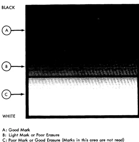
[image:12.613.299.537.57.351.2]the following categories: 1. Good
2. Poor 3. Uncertain
A good mark is recognized as a posltlVe indication of a mark; a poor mark (or good erasure) is not
recog-WHITE
A: Good Mark
B: light Mark or Poor Erasure
C: Poor Mark or Good Erasure {Marks in this area are not read}
Figure 9. Mark Reflectance Relationship
nized as a mark, and an uncertain mark (light mark or poor erasure) is one whose light reflectance level comes somewhere in between a good mark and a poor mark, but cannot be positively identified as either. The reading or rejection of uncertainties can be customer-controlled.
Three read-mode switches, each associated with a set of field-checking switches, allow operator-control of mark discrimination on a field-by-field basis. Documents containing uncertainties can be selected for a visual check if desired.
Each of the three read-mode switches has four settings:
SING RESP (single response); MULT RESP (multiple
re-sponse); SING RESP SEL UNC (single response select un-certainties), and MULT RESP SEL UNC (multiple response select uncertainties).
The setting of each read-mode switch affects mark discrimination (Figure 9) as follows:
1. SING RESP:
a. Marks in area A are accepted.
b. Marks in area B that are not accompanied by a mark in Area A of the same word or segment are accepted.
*
c. Marks in area B that are accompanied by a mark or marks in area A of the same word or segment are not accepted.
*
2. SING RESP SEL UNC:
a. Marks in area A are accepted.
b. Marks in area B that are not accompanied by a mark in area A of the same word or segment cause the data sheet to be selected.
*
c. Marks in area B that are accompanied by a mark in area A of the same word or segment are not accepted as marks.
*
3. MULT RESP:
a. Marks in area A are accepted. b. Marks in area B are accepted. 4. MULT RESP SEL UNC:
a. Marks in area A are accepted.
b. Marks in area B cause the document to be selected.
Whenever a data sheet is selected by the 1231, storage is cleared and data from that data sheet is not transferred to the computer. However, in the 1232, the information is transferred to the 534 Card Punch and a card is punched. The word or segment in which the uncertainty is detected is transferred to the card punch as a blank character, and the ll-punch in column 81 is inhibited.
Data
Flow
The entry of data, control bits, and master data into the IBM Optical Mark Page Readers depends upon whether the reader is a 1231 or a 1232. The differences result because of the storage units used, the internal transfer of the data, and the storage used as output to the processing system or to the IBM 534 Model 3 Card Punch.
IBM 1231 Data Flow
Before the 1231 can act as an input device to a data processing system, the controls for the internal functions must be loaded and switches must be set to establish the conditions required for the particular run.
Two storage devices (sonic delay lines) are used to store and control the data as it is read from the data sheets. One of these storage devices, the "master" line, is used to store all the controls from the program control sheet and, if the 1231 is equipped with the Master Mark special feature, master-mark data and controls associated with master-mark data are also stored.
The other storage line, the "data" line, is used to store information from the data sheet. As the data sheet is read, the two storage lines work concurrently and in synchronism. The master line, which contains the pro-gram instructions, determines which information from the data sheet is to be retained.
*The number of mark positions included in anyone mark
discrimi-nation test is determined by the setting (SEGMENT or WORD) of
the check-length switch.
[image:13.617.68.306.131.374.2]The following sequence is used for entering data into a fully equipped 1231, and for making this information available to the processing system (Figure 10):
1. Line mark and word mark bits are generated by internal circuitry to establish the starting point of the data on the delay lines. These bits go into the
I
data delay line.2. Program control bits are loaded into the 1231 from the program control sheet, and go into the master line.
3. Master-mark information (if Master Mark special feature is installed and being used) is entered into the first ten positions of the master line.
4. Detail data reads into positions 12 through 111 of the data line.
5. A READ instruction from the processing unit causes
the data (master and detail) from the master line and the data line to read out in sequence into the A register. The master data from positions 1 through 10 of the master line reads out first, followed by positions 12 through 111 of the data line.
The master and data lines read into the A register one segment at a time. Data is transferred from the A register to the B register between segments. While data is transferring from the B register to the processing Systeln, the A register is receiving data from the next segment in storage. As data is transferred from the delay lines to the A register, each character is checked for odd-parity.
am Control 8lh
Master Marie Data
Detail Datu
Moster Line
Data Line
Figure 10. IBM 1231 Data Flow
IBM 1231 Message Format
A Reg
C
A
Reg
To
Computer
Each \V'ord transferred from the 1231 to the computer reads into two adjacent positions of computer storage. Words are transferred one segment at a time; each segment entering one computer storage position. Words with marks in positions 0, 1, 2, 3, or 4 transfer to the computer as A, B, 1, 2, or 4 bits. Combinations of these bits make up a valid character. Similarly, marks in positions 5, 6, 7, 8, or 9 transfer to the computer as A, B, 1, 2, or 4 bits. Any or all of the marking positions on the data sheet may contain marks, and the data will
14
be transferred to the computer as a valid combination of bits.
NOTE: \Vhcn a zero or a five is the only mark read
within a segment, the mark is transferred to the computer as an A-bit onlv. If the mark is then written onto a tape instructed to
w~ite
in even-parity, the A-bit is combined with a C-bit. This combination represents a substitute blank character when read out of the tape to the com-puter. The original mark on the data sheet has lost its identity. If the A-bit is first translated into some normal core storage character (i.e. an 8-2 for a numeric zero) before writing itonto tape, its identity is retained. Also, if the tape unit is instructed to write in odd-parity, each character transferred from the 1231 will retain its orig-inal core storage identity.Data is read by the 1231 from left to right, top to bottom, a row at a time. Information from a data sheet is stored in the following sequence:
1. Segment one of the first word programmed to read.
2. Segment two of the first word.
3. Segment one of the second word programmed to read.
4. Segment two of the second word.
If only one segment of any word is programmed to read. only one position of computer storage is used.
IBM 1232 Data Flow
The 1232, when used with an IBM 534 Model 3 Card Punch, uses the facilities of both units for controlling information as it is entered, transferred, and made avail-able to the 534.
Program control bits are entered into the 1232 storage from a program control sheet. Master data, to be retained until the next master data sheet is read, is entered into the first ten positions of storage. Detail data enters -StQrage in positions 11 through 110.
In a fully equipped 1232, the following sequence is used in entering the program controls, master data, and detail data into the machine (Figure 11).
1. Line Mark and ''''ord ~1ark bits are generated by internal circuitry.
2. Program controls are loaded into storage delay lines 1 and 2.
3. Master data is read into delay line 1 (first 10 posi tions) .
4. Detail data is read into delay line 1 (positions 11 through 110).
5. Controlled by the 534 program card, master and detail data are read from line 1.
[image:14.612.38.281.438.543.2]Pch Reg
r0-O 0
Group I I
Count 2 2
3 3
~ 4 Note I
T
I 56 6
* 7 7
534 Program Card (3) 8 8
Segment 9 9
Program Control Bits
-Delay Punch
Master Mark Data Line Mode
Switch Detail Data
Pch
* Word Reg 12
534 Program Card (2 or 9)
ro-
J]0
I I
* 2 - Punch Master or Identification Data 2 2
3 - Punch Group Count or Card Number 3 3
6 - Sync Check Card Column 4 4 Note I
8 - Sheet Feed (1232) 5 5
9 - Punch Detai I Data Note: 6 6
I Punching in either 7 7
Segment or word mode 8 8
is limited to 3 punches 9 9
~
per card column
Figure 11. IBM 1232 Data Flow, Including Segmented Word Feature
IBM 1232 Message Format
Each word transferred from the 1232 to the 534 transfers digit-value-for-digit-value. A 9-mark in a word on the data sheet would transfer and punch as a 9-punch in the card; a 3-mark and a 7-mark in one word would transfer and punch as a 3-punch and a 7-punch in one card column (when the 1232 is operating in word mode). When multiple punches in the card are not a standard card code, a special feature may be required on the
I
using system. For example, the Column Binary special feature is required for 1401 processing; the Card Image special feature is required for 1440 processing.
The data sheet is read from left to right, top to bottom. one row at a time. All like data (identification or detail data) will transfer to the 534 Card Punch in the sequence read. If the first ten odd-words on the data sheet were identification data (available only on machines equipped with
either the Multiple Spread-Card or Unit Record Card feature)
and the first ten even words were detail data, the data would be stored in alternate positions as read. In this case, the first word in storage would be identification data, the second word would be detail data, etc. When the data is called for by the 534 (a 9 punch calls for detail data, a 2 punch calls for identification data), like data would read out of 1232 storage as it was read. If identification data were called for in the first ten positions of the 534 program car~, only the odd words (1 through
19) would read out and punch. Even words 2 through 20 would read out and punch when detail data is
re-I
quested by the 534 program card. If a word on the data sheet is not marked but the program control sheet calls for reading of the unmarked word, the associated card column is spaced over.
IBM 1232/534 Synchronization Check
Words that are read by the 1232 must be punched in the correct card columns by the 534. This synchroniza-tion is accomplished through the programming of both machines. Two programming procedures are involved; the marking of the program control sheet used in the 1232, and the punching of the program card associated with the 534.
When the 1232 program control sheet is marked, a mark in position 4 and a mark in position 8 designates the word as a sync-check word.
When the 534 program card is punched, a 6-punch and a 9-punch in a card column designates a sync-check card column. Failure to match the sync-check word with the sync-check card column causes the machine to stop and the punch-check light to turn on.
To maintain maximum sync-checking on each card, the sync-check card column should be the last column of detail data programmed to punch. However, because a sheet-feed instruction can be programmed (534 pro-gram card) as many as eight columns ahead of the last
[image:15.617.75.542.60.335.2]column of data to be punched, a sync check could occur either before or after a feed instruction.
A sync check before a feed instruction requires the reprocessing of only the last document read. A sync check after a feed instruction requires reprocessing of two documents: the last one stacked, and that in the 1232 transport.
When synchronization check is used with either the Multiple Spread-Card or the Unit Record Card features, sync-check words in the 1232 must be programmed to correspond to the last column punched in each card. Then, the sync-check words and the sync-check card columns will match when multi pie cards are punched for a data sheet.
When punching is in segment mode (Segmented Word feature) the two card columns that correspond to the two segments of the sync-check word must be pro-grammed as sync-check columns. However; when only one segment of the word is to be punched, only one sync-check card column is needed.
Field
elteclcing
The field-checking feature, standard on both the 1231 and 1232, allows each word programmed to read to be checked for mark conditions which may indicate invalid data. Three switch-controllable mark 'conditions, each of which will cause the document to be selected, can be checked. These conditions are: Multi-marks, No marks,
and Other-Than=One. The svvitch. also has
an
"off"position.
Data sheets are usually designed with "fields" of similar data in vertically consecutive words on the left or right sides of the data sheet. The policy number field, shown in Figure 12, is an example of a data sheet field.
A field-checking field differs from a data sheet field
primarily in functional grouping. A data sheet field groups similar information for ease of marking and reference. A field-checking field may contain part of, or several data sheet fields. The primary requirement of field checking is that all mark data within a field's area of coverage be checked for the same conditions (multi-mark, no (multi-mark, etc).
T.J:le field-checking fields on the data sheet are defined by special codes (start-of-checking codes) which are entered into 1231/1232 storage from the program control sheet. A field-checking field can be from one to one hundred words in length.
Three start-of-checking control codes allow any spe-cific area of the data sheet to be checked according to one of three groups of field-checking switches. The three groups of field-checking switches are labelled; Field I, Field II, and Field III.
The checking of a field-checking field by a particular group of switches begins on the word in which the
field-16
checking control code is recognized. On the program control sheet, a mark in position SIX designates the start
'of data checking according to conditions set up in Field I switches; a mark in position SEVEN designates the start
of data checking according to conditions set up in Field
II
switches; marks in positions SIX AND SEVEN designate the
start of data checking accordine- to Field
III
switches. A new data sheet always starts checking according to Field I switches unless programmed otherwise. Figure 13 shows the program controls needed to read and field check the illustrated insurance form. The setting of the switches is shown in Figure 12 .Three switches are assigned to each field: (1) a read mode switch, which determines how uncertainty marks are handled; (2) a check length switch, which determines whether information is to be checked on a word or segment basis; and (3) a select condition switch, which determines the conditions for which a data sheet will be selected.
Because the data sheet is read from left to right, top to bottom, row by row, field checking becomes an im-portant factor when a new data sheet is to be designed. If, for instance, the data sheet is to be used for a "yes" and "no" survey, the yes and no mark positions should be within one segment or word in order to allow check-ing for both, either, or neither answer.
The field checking feature can be summarized as follows;
• Each of the three field-checking switches can be set to one of the select conditions; or to the OFF
position.
• Unless programmed for another field, checking al-ways returns to Field I at the start of a new data sheet.
• Field checking by a given set of field-checking switches begins in the word programmed and con-tinues (in all words programmed to read) until a new field checking command has been recognized.
• A field can begin or end on either the left or the right word.
• A field can be from one to one hundred words in length.
e
Three conditions can be checked: OTHER -THA~,J -oy..~E(multi-mark and/or blank detection), NO-MARK
(blank detection only), and MULTI-MARK (multi-mark detection only).
ANY LIFE INSURANCE COMPANY INDUSTRIAL APPLICATION
oArE OF POLICY
I
POLICY NUMBER I :::::p o L I C y
I Your FULL NAME (Print
FIELD I
~. -IQC' ° "irln (STATEI 1'4. DATE 01' IIIft1 H I" _ LAST ""Ih .. , MONTH DAY YEARI ___________ .Y ....
N U M B E R
What.1 rour 13. BENEFICIARY (Print FULL NAME) heithl and .,iOlll' ____________ "- ____________ 1 .... _____________ lbo.
8. 00 you now how insurance with Uti ANY LIFE INSURANCE COMPANY.?
IF YES, WHICH. "'IOHSHP OF BENEFICIARY SIIOO .-7"0 FIELD II
9 POLICY APPLIED FOR FACE AMOUNT PURCHASE (.1 PLAN
::::: WL 75 -:::- [10 FIELD III ~:~: ~
..
-~~FIELD III ._~C?
: I!5PL -:::: ZOPL
~;~: t~~
c:.~~
-~:~~~ FIELDII IFY ON a.CK 10. av. you n 'ft' palt I'll .. r or a IInau.
di •• nl. oilmen', or di,.bility. o. ...Inmon cold, virul or lfIinor bonl 'rac,,,,. and lueh co".ve'at'" ,.,.,It,d in trlCitment dich lac.,eleel • period of on. w .. , ?
10 (0) OCCUPATION, Job titll, and no lu • • " , work performM.
II. A G E H E IA li W E I G H
rI-If job title applars betow chick mark it otherwi •• cOIRPII" Quntion,I' on lItock.
(0) Job lill, (eI8_ ... ado
'0" FIELD II
QUARTDlLY _ - _ A L AINIAL
I ::t- 4
TENS __ L ::~:: _.L __ L __ t __
::C?:: -:1:: _2 __ --~:c UNITS __ L --!-- _L --!-- __ L
-~- 4 -~-:
.
_L FEETFIELD r J any '''reical dlflc' or impairm.nt of hlol'h?
If '00 •• ,IClin on back.
I
.
win". tllO •• t I . ' ' ' ' ' , . . . . ,ou _ • • ,e 1ft", pOI pon,.,or off.r." a potic, oth,r tit ... ,ppli,d for by 'hit or ... , oth'r COlnpony?
-YES
-liO-If ,.1 ••• plain on back.
FIELD I
"opticallt r.,id. In I."' •• tat. In which offiCI it loeat.d?
tcelPATIOI
_____ co.
-T- -"4"" --D--
--.--19. REPORT OF FIELD REPRESENT .. TlVE
+-=-,-::?:: I L __ L L __ L
- - : - - - : - - - i HaWl JDU chlck.d above application to Make aur. oilitemi and
::~:: ::!:: ::~: :!!:: FIELD
__ 9 __ _:L
--~--::~:: I :c~:: --' :c~:: 10'S
__ C? __ I __ 1_- ,,~:- --~-UNITS
'"
~: ~:__ t __ __ L 7
::t: --!-- 7
JNCHU
POUNDS
--,--
--,----!--
--!--.. ,.tiona ar, an ••• ,.? :::::: YEI :::::NO
00 ,ou c.rti" that all information contoh,.d on thi' REPORT OF FIELD REPRESENTATIVE i • • Iru, .. d e.r,.et cop, 01
"'forM.tiOft which ap ... .,. on application?
c..:..:.:..:.._ , - - - 1
II_TURE OF
fELD REPRESENTATIVE ___________________________________________ _ 20. I h.,. by "quI.t that an, DIVIDENDS payabl. und.r the policy appli.d for .. '
UNTIL AND UNLESS ANY OTHER OPTION SHALL BE SELECTED IN A'
• to tho pureha . . of PAtD UP ADDITIONS TO THE SUM INSURED . TERMS OF THE POLICY.
The forl,oin, Itatllft.nU and ana . . ,. or. true ond compl.t. FIELD I ) th'" ,tat . . . "tl .. d an, •• r. Ihall form the balil of thl contract of inlurance if on. i. illu.d, (2) no ag.nt or any oth, ."r'lid.nt, or S.cr.tary of the Company, hal po •• r on bettalf of the Company (a) to moll., ",odlfy or dilcharg. any contro.. '" (b) to bind the COMpan, by Mallin, any prom .... r.lpacli_. any ban.fits undar an, policy illu.4 htr.und.ri (3) th. COMp.y will incur ftO liability by r"lon of thll applic.tion .IC.pt a. m.y bl proyid.d in a Conditional R,clipt ,iv.n on an4 b.oring UI' 10"" clat, al thll .ppUcottoft, until a polic, hal b •• n d.liv.r,d and thl hI! fir.t prlmium hal bl.n paid to thl COlllpany.
Amount paid in a dyonCi on account of Dat.d at __________________________________ thll __ ~ ~ _ • _____ da, of _________ • ________ _
Fir.' Premium $ --- Signature of Applicant ... _ .... _ •... _ ...•... _ .. _. which do":~ . do.s not· ,."..ent full fir.t ".mium
Si,,,,tur. 0' Wit ... _ ... ' .•... _ ...•...•.•.•...•...•..
Sing~
Resp~
Sing~
Resp~ S i n g - Q Resp~R E A D MODE
-(jro
S09"U
Word
CY
---CHECKLENGTH---Other Mu Iti Mu Iti
O~~~ ~a_rl< ~arl<
SELECT CONDITION
-FIELD I SETUP
Read Mode Switch---Set to Sing Resp Check Length Switch---Set to Word
Select Condition Switch---Set to Other- Than-One
FIELD II SETUP
Read Mode Switch---Set to Sing Resp Check length Switch---Set to Word Select Condition Switch---Set to Multi-Marl<
FIELD III SETUP
-
00 ~ aq' c.,
~ -~ '"C.,
0aq
.,
8
Q 0a
g.
\Jl ::r ~ ~ 0'.,
~ ~ ~0-s·
aq ~ t:I 0-~ [ 0-n ::r (l ("J :>;'" S' aq C/l III 8 '2. (l "!'J 0 ""I 8ANY LIFE INSURANCE COMPANY
INDus'rRIAL APPLICATION
DATE OF P O L 1 C ) ; - - ; - - - POLICY NUMBER
'
-I Your FULL NAME {I'flnt:
--s- "i--
-7-""
-,-(~l.ILL F1Rsr--NAMt:)- (Mlb-c5Lf~: lNITTALJ ,LAO) 1 I'tIo\Mt:./
"2 RE~.IDENCE (Pnnt) NO STREET lorn
y
N U
M
. .
,.
_:;0 . . . . i-___ VIars
8
t.fcW~i':j WidoW-lei Si~~: • . - E
R WhlJf II your
htuJhl and .elght? . 11 8 Do you now have lrluranCI with Ihe ANY LIFE
INSURANCE COMPANY?
= I b •
-YES NO
"
""",""""""",, ._, r
14 illATIONS!:!!!,J)E BENEFI~Afl.l' - - - -IF YES, WHICH?
12'0 • '00 ;m - $1000
9 e.Q:~g_YAllilli>_J;Q!! - - - . fAg;_.~MQ\!!JI...f'J,I~A.KQ (al PLAN
.
~, ~ '.7.' .
$100
:.=
'.'"0 *,'0 $100020PL
HL!~.A_NO
-~g~-D~~~,!,ER BI'IOTH.ER SI~T~R
~~~f SPECIFY,.LBACJ-. f5 Hay. you in the pas I five years consulted a doctor fOI a serioul
dille,., ollment, or disability, other than a common cold, lIifUS or minor bon, ffllctur" and IUch con."ltation r •• ult.d in treatment which ".ce.dtld a p.riod 0" one week?
~
ro.--foT OCCUPATION.Jci"titI8,"~tUr'i-of work perform.do
---1
If job title appeon. below cheCk .nark It oth.rwise compl.te Que.tionIIOcl.b,c, ~~ physical defect or ImpClirment of health? on bock
(0) Job title (bl Nome of (cl Bu,in", addr .. , Pr ... nt Employer
Y£S
-NO--HO~S~WIFE STUI?'~..Nl C:l:~_~k UNE'!IP_LOYED
1\ eRI;MIUJ!J''lYl\.ID,lC---
--
_ _ -+1=--elf yII. Ixplaln on. back.
11, Within th" lalt 'tVI yeaft have you I)"," declined, poatponed. or off Ired a policy other than applic.d for by this or
~ : : : -QUARTERLY S£Mt-... UAL 12. ~b-'\S§!E!C.~_J'l.2!'I
-STAND.lIRD RAffNG RAT-ING 3
A G E H E I G
.
- TE NS IUNITS
---~--'----4---"co. _ OTHER SPECIFY ON BACK
.:.
.
7 ..
..:..
7-.M:ET
~HES ~ , " _ _ _ L.:..{ • .--:=:...:=-...I.I.L.~~ _ _
W E °
I °
G
-H °
100'5 10'5
.... UNDS
.
7.:..
,.~"ony oth.r company? __ _
-YES NO
If ye ... plain on back.
18. 00 . . applicant reside in lome st01l ir. which distrtct offiCI II located;:
YES
',-
4--Do you certify that all il,formation contain.d on thil REPORT OF FIELD REPRESENTATIVI~ il a true (lnd correct cop-y of tnformation which appian 'HI application?
..:..
T .. _ _ _ _ _ UNITS I SIGNATURE OF
-NCf
FIELD REPRESEN-rATiVE ________________ . ____________ ._ , ____________ _ 20. I tlereby request that any DIVIOENCIS payable uf'lder tl'le pOlicy applied for shall be applild to thl purchase of FAID UP AOOllolONS TO THE SUM INSURED
UNTIL AND llNLESS ANY OTHEI~ OPTION SHALL BE SELECTED IN ACCORDANCE WITH THE TERMS OF THE POLICY
Ttle foreooing .tatements and anlwerl are true and complete and it IS aQr •• d that: (I) ttllle statem"nts and an1Wln shall form the bosi, of the contract of Ulluronce if OM i, ISlUld\ (2) no aoent or any other p.non. ucept Ihe Prelullnl. or Secrlltary of the Company. hal power on blhalf of the Cotrpany (0) to make. modify or dilcharge any contract of insurance or (b) 10 bIRd the Corn pony by mokino any promia . . r.spectlno >lny b.nefits under any policy luued hereunder; (3) the Company Will inCur no Ilab lity by realon of ttlia a,pplication ucept al may be provid.d In a Con'~itlonol Receipt given on and beanno Uti .aml dot. 01 this application, until a policy hlu been deliv.red and th" full first promlum hal been paid to the Compa"y.
Amount paid in udvance on oCI;ounl of Dated __ this ___________ day FIrst Premium 1 Sionalure of Applicant
which does doesnol_ rlpre .. nl full first premium ~ionaturl of
PROGRAM CONTROLS ILLUSTRATED
Mali< in position 8--Read word.
Marks in positions 6 and 8--Read word and check data according to Field I switch setup.
Marks in positions 7 and 8--Read word and check datlJ according to Field II switches.
Malrks in positions 6, 7, and 8-- Read- word and check data according to Field" I Sowitch setup.
Marks in positions 4 and 8--Read word. The 4 disignates a sync-check word for 1232 use with the IBM 534 Card Punch.
PROGRAM CONTROLS NOT ILLUSTRATED
Marks in positions
o
and 8--Read segment one of the word so marked.Marks in positions 5 and 8--Read segment two of the word so marked.
Malks in positions 3 and 8--Read nnd store this wOl'd as identification data. This program control is used with either the Multiple Spread-Card or Unit Record Spread-Card features on the 1232 onl;( .
Alphabetic Coding
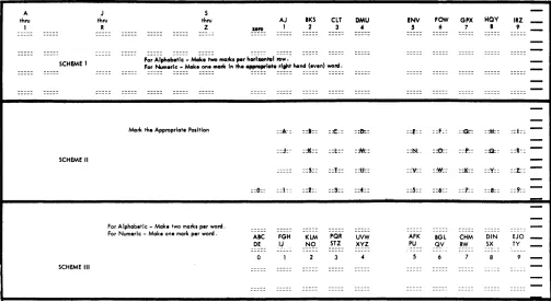
An alphabetic coding capability is necessary and desir-able in many applications. Three methods of alphabetic coding are illustrated in Figure 14.
Scheme 1: To code an alphabetic character, a mark
must appear in the appropriate marking position of both the odd (left hand) and even (right hand) words of the same horizontal row. For example; to indicate the letter K, one mark must be made in the marking position immediately below the caption "] thru R" in the odd word, and one mark must be made in the marking position immediately below the caption "BKS" in the even word of the same horizontal row. The odd-word, in this scheme, represents the zone portion of the character. In 1232/534 application, two card columns will be used for each alphabetic character marked. Marks in positions 0 through 9 of each word will punch as 0 through 9 punches, the same as normal numeric punching.
Scheme 2: Each letter of the alphabet can be preprinted
on the data sheet in reflective ink. The letters and/or numbers may be printed above, on, or below the mark positions. In this approach, the identity of each character is determined by its position in the matrix, which is programmable.
A thru
I
SCHEME 1
SCHEME II
SCHEME III
J thru
R
Marl< the Appropriate S thru
Z
POlltlon
[image:19.612.73.576.418.694.2]For Alphabetic - Make two marl<l per word. For Numeric - Make one marl< per word .
Figure 14. Alphabetic Coding Schemes
::6::
AIC DE
The entering of the marks is simple; however, considerable space is required on the data sheet to represent all the alphabetic and numeric characters. Four card columns are needed to represent all the alphabetic and numeric characters. An "A" would punch as a "1" in the first of the four columns; a "Y" would punch as an "8" in the third column.
Scheme 3: Each letter of the alphabet, or digits 0 through
9, can be represented by using only one word. An alphabetic character must be represented by a mark in each segment of the word selected for this purpose ("Z" is an exception). To indicate a "K", marks in the 2 position of the left-hand segment and in the 5 position of the right-hand segment are required. Each character is represented by a unique combination of punches.
For instance; suppose an "A" is marked in positions
o
and 5 of a word. If punching is on a word basis, the "A" would be represented by punches in positions 0 and 5 in a card column; the letter "X" would punch as a 4 and 8 in the corresponding card column.Controls
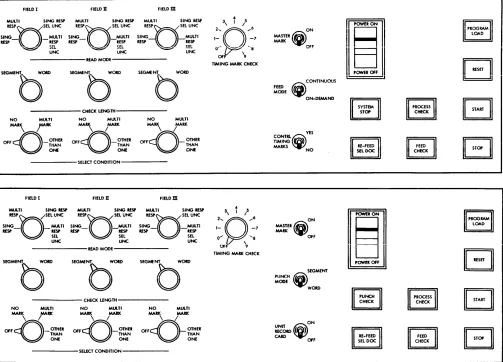
The operator's console (Figure 15) on the Optical Mark Page Reader contains the keys, lights and switches necessary for setup and operation.
AJ 1 ::k: ::j:-::1:: FGH I~ IKS 2 ::1:: :::If:: ::5:: ::2:: KLM -~g-ClT 3 ::t::: ::t:: ::1:: ::9:: PQR STZ DMU 4 ::0=: :jic: ::tt.:: ::4:: UVW XVZ !NV 5 ::E:: ::ht ::'1:: ::.5:: AFK PU
FOW GJlX HQV
6 7 I
::F: : :~ ::M::
::0:: ::f::: :~:
:~: ::X:: ::Y::
::6:: ::'1:: ::8::
BGL CHM DIN
_~V RW SX
IRZ _
9
::t::
-::R~:-::I::
::9::
-EJO
-TY
-9
Keys and Switches
Start Key: A depression of the start key feeds the first
data sheet and establishes continuous running con-ditions with two exceptions: (1) If the feed mode switch on the 1231 is set to CONTINUOUS, the feed
circuits are interlocked with the program of the processing system and will not feed the first sheet until the processing system is placed in an operating status, and (2) if the Reader is in a load program cycle, the program control sheet feeds and the control bits are stored.
Stop Ke.:v: A depression of the stop key halts document
feeding and lowers the hopper plate to facilitate the loading of more data sheets.
Reset Key: A depression of the reset key raises the hopper
to the feed position and resets the electronic circuitry. Check or error conditions should be corrected before pressing the reset key.
Program Load Key: A depression of the program load
key clears the delay line storage of previously-stored data, and conditions the machine for program
load-FIELD I FIELD II FIELDm
MULTI SiNG RtSP MULII SiNG iESP MULl I SiNG iESP
ing. This key is lighted during the program load cycle.
Master Mark Switch: The master mark switch is active
only on machines equipped with the Master Mark special feature. This switch controls the capability of the Optical Mark Page Reader to recognize a master mark on the right edge of the data sheet. When this switch is on, the recognition of a master mark causes the data in the first ten positions of storage to be cleared and new master-mark data to be accepted.
Feed Mode Switch: The feed mode switch (1231 machines
only) has two settings: CONTINUOUS and ON-DEMAND.
When the switch is set to CONTINUOUS, documents feed continuously. This setting requires the processing unit program to give a read instruction within 150IDS after buffer full in the 1231. Buffer full can occur as fre-quently as once every 1585 IDS. When the switch is set to ON-DEMAND, feeding is controlled from the system program. The next document will not feed until the contents of the delay line (from the previous docu-ment) is transferred to the computer.
REspnSEL UNC SING_
n
_MULTI RESP RESPR E S P n SEL UNC SING_
n
_MULTI RESP RESPREspnSEL UNC SING_
[J
_MULTI RESP RESP2 .... 3
0 '
/ ...
61- -7
ON MASTER~
MARK
I~I
Ilgll
r=ll
lElll
..
,' = ' ...
UNC
~ SEt. uNC ~ ~~
R E A D M O D E
-SEGMENT_ WOlD
0
NO MULTI
MAR\ rRK
OFFcQ_OTHER THAN
ONE
FIELD I
MULTI SING RESP RESPQSEL UNC SING_O_MUlTl RESP .ESP
SEL UNC
SEGMfNl.. WOItD SEGMfNT WOlD
0
b
CHECK LENGTH
NO MULTI NO MULTI MARK MARK MARK MARK
~OomB
THAN~'<)_mHn
THANONE ONE
SELECT CONDITION
FIELD II FIELDm MUlTI SING RESP MUlTI SING RESP RESPQSEL UNC I E U / S E L UNC SING_
0
_MUlTI SING MULTI RESP RESP RESP - .ESPSEL SEL
UNC UNC
R E A D M O D E
C H E C K U N G T H -NO MULTI NO MlA.TI NO MULTI MAR\
rr«
MARK MARK MARK MARKOFFD-~.:~R
O F F D \ I_~.:~.
O F F D - ' /~~If
~
ONE~
ONE~ONE
---SEUCT
CONDITION---0'- ~, ~'8
OFr' 9
TIMING MARK CHECK
2 .... Q 3
0
,1
l ... 61- -7
0...
,
...8 [image:20.612.39.542.333.695.2]OfF 9 TIMING MARK CHECK
Figure 15. Operator Console (1231 upper view; 1232 lower view)
20
"".
<i)
CONTINUOUS FEED MODE ON-DEMAND YESCONTRLCiY
TIMING ~ MARKS NO
ON MASTER fiiM
MARK
¥
OFF(i)
SEGMENT PUNCH MODE WOlD ON ~;6.0~ CARD ~OFF, I
~
IILJ,--II
~
~
~
II 'I
Punch Mode Switch (SPecial Feature): The punch mode switch (1232 only) has two settings: "Segment" and "Word". When the switch is set to SEGMENT, punching
of the card in the 534 is on a segment per card column basis. When the switch is set to WORD, punching is on
a word per card column basis. Master mark and identi-fication data always punch on a word basis, regardless of the switch setting.
Check Length Switch: Three check-length switches are
located on the operator's panel; one for each of three sets of switches associated with fields. These switches have two settings: "Segment" and "Word". The setting defines the length of the item as it will be checked for each field. The SEGMENT setting will
check the five positions of a segment; the WORD
setting will check all ten positions of a word.
Select Condition Switches: Each of the three select switches
has four settings: "Off", "No Mark", "Multi-Mark", and "Other-Than-One". Each switch is associated with a check length switch and one of the three fields. The settings represent the conditions in a given field under which a document will be directed to the select stacker.
Unit Record Card Switch: When this switch is on, the
1232 operates in unit-record card mode; one card is punched for each field. When the switch is off, one card is punched for each data sheet.
Read Mode Switches: These three switches, each
associ-ated with a set of field-checking switches, determine the conditions of mark discrimination. Each read mode switch has four settings: Single Response, Multiple Response, Single Response-Select Uncer-tainties, and Multiple Response-Select Uncertainties.
See Mark Recognition and Discrimination in this
publica-tion for a detailed descrippublica-tion of each switch setting.
Control Tzming Marks Switch: This switch enables the
1231 to eliminate the 75ms delay associated with the timing-mark-checking feature. The switch has two settings, "Yes" and "No". YES is used when the documents to be processed have the six, extra, control-timing marks needed for IBM 1230 operation. NO is
used when no control timing marks are on the docu-ments; the 75ms delay is eliminated.
Timing Mark Check Switch: This switch is an II-position
rotary switch with settings numbered "0 through 9" and "Off". The switch is preset by the operator to match the units-position count of timing marks on the data sheets to be processed. For example; if there were 1 06 timing marks on a document to be processed, the switch would be set at "6".
Lights
Start
Key
Light: The start key, when lit, indicates thatthe machine is in a ready