Technology (IJRASET)
©IJRASET: All Rights are Reserved
130
Fault Detection and Autoline Distribution System
with GSM Module
Neeta D. Sonwane1, Prof. Devidas D. Dighe2
1
Student , 2Professor, Department of E&TC, Matoshri College of Engineering and Research Centre, Nashik, Savitribai Phule Pune University,Pune, Maharashtra, India
Abstract - Transmission lines is the important factor of the power system. Transmission and distribution lines has good contribution in the generating unit and consumers to obtain the continuity of electric supply. To economically transfer high power between systems and from control generating field. Transmission line run over hundreds of kilometers to supply electrical power to the consumers. It is a required for industries to detect the faults in the power system as early as possible. “Fault Detection and Auto Line Distribution System With GSM Module” is a automation technique used for fault detection in AC supply and auto sharing of power. The significance undetectable faults is that they represent a serious public safety hazard as well as a risk of arcing ignition of fires. This paper represents under voltage and over current fault detection. It is useful in technology to provide many applications like home, industry etc..
Keywords: Fault, Fault Detection and types, Auto line distribution using PLC, GSM Module, Relay Switching.
I. INTRODUCTION
Electrical fault is the deviation of voltages and currents from normal values or states of input signal. In normal operating conditions, power system equipment or lines carry nominal voltages and currents which results in a accurate and good operation of the system. This paper represents the Line Protection on the applications of fault detection technology. This addresses the detection of those abnormal conditions where a conductor suffers from under voltage and over current condition. Detection of fault on line parameter (current and voltage) is done by using current and voltage sensor. If there is any fluctuation in parameter for more than 3 second than it will consider fault condition and load will share power from other load. Because in many application, machine or devices may have capacity with stand the fluctuation for a particular time. This system introduced with the 3 second of time period. Automation of system has become the demand of the day. In fact most of the system are impossible to be controlled by human being. As fault analysis became important requirements of the electric power system to became more accurate. The need of automatic fault clearance became a necessity.
There are combinations of a circuit breaker and a relay protection system in a typical fault cleaning system. The main parts in protection system are wiring, transducers, auxiliary power supply, switches, circuit breakers, relays and the operating coil of the circuit breaker. Earlier fault is automatically cleared by electromagnetic relays. The electrical quantity, which is voltage or a current, was transformed to a mechanical force which operated the relay when a preset threshold was exceeded. But now a days the solid state relays are developed so that the operation can be performed easily and accurately.
II. LITERATURESURVEY
In order to start the thesis, the first step is to study the previous work performed by researchers. For this purpose, various papers have been studied.
TABLEI
RELATED WORK
Sr. No. Paper Title Year Work
1. Fault Detection Techniques For Power
Transformers
2007 Author investigated An artificial neural
Technology (IJRASET)
©IJRASET: All Rights are Reserved
131
2. Optimal Coordination of Automatic Line
Switches for
Distribution Systems
2012 Author focuses on distribution feeder
automation system; protection coordination; underground 4-way automatic line switch This study investigates the coordination time intervals (CTIs) among the protection devices of the duty point of high voltage customers, automatic line switches lateral protection relays,
3. High impedance fault detection of
distribution network by phasor measurement unit
2013 Author estimated the High-impedance faults
on distribution feeders are abnormal electrical conditions that cannot be detected by conventional protection schemes because of the low fault current due to the high impedance fault at fault point.
4. Cable fault monitoring and indication 2013 Underground cable power transmission and
distribution system are susceptible to fault. Author introduced power fault, fault, fault location, time domain reflectometer.
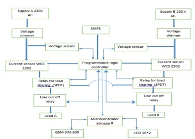
[image:3.612.97.493.338.620.2]III. BLOCKDIAGRAMOFPROPOSEDSYSTEM
Fig No. 1 Block Diagram of Proposed System
Technology (IJRASET)
©IJRASET: All Rights are Reserved
132
A. Modules for Proposed System
Design of system divide in two parts first part is to detect fault and Second part is to sharing of power between load.
B. Fault Detection
This system consists of voltage sensor and current sensor that sense the change in current and voltage from a particular value, which is use for gathers information of fault from input section then process on PLC and send data to display on LCD, which show Fault detection station. In this under voltage and overcurrent fault detection is done by using sensor unit.
C. Processing Unit PLC
This section is used for continuous measurement of various Monitoring and controlling parameters like voltage and current etc. PLC receive analog DC output voltage and change the polarity of relay if there is a fault condition. Aimed to help protect the device from over current and under current protection.
IV. SYSTEMOVERVIEW
A. Voltage Sensor / Voltage Transformer
Voltage transformer (9v, 500mA) is used to covered high voltage to low voltage. As a result, we get a constant ratio of voltage, with the help of rectification circuit we get constant DC voltage. which is proportional to input AC voltage (230v).
B. Current Sensor (WCS 2202)
A current sensor is a device that detects and converts current to an easily measured output voltage, which is proportional to the current through the measure path. The WCS2202 consists of a precise, low temperature linear hall sensor IC with temperature compensation and AC to DC rectifier circuit.
C. Programmable Logic Controller (SR3B261BD)
A PLC is an example of a hard real time system since output results must be produced in response to input condition with in a bounded time, otherwise unintended operation will result. SR3B261BD is analog input PLC operated at 24v DC. A SMPS of 24 v DC and 1A is used for PLC.
D. ATMEGA8
The AVR is a modified hardware architecture 8 Bit RISC single chip microcontroller which was developed by ATMEL. The AVR was one of the first microcontroller families to use on chip flash memory for program storage. Here there is the interfacing of PLC and microcontroller.
E. LCD
A LCD 16*2 display is connected with the microcontroller. when the fault is present microcontroller recognize it and then save text command for that fault detection station and display on LCD screen.
F. GSM SIM900
GSM module featuring an industry standard interface, the SIM900 delivers GSM/GPRS 850/900/1800/1900 MHz performance for voice, SMS, data and fax in a small form factor and with low power consumption. 12 volt, 1A adaptor is use for power supply for GSM module.
G. Relay SPDT
Relay is used for switching purpose And load sharing when fault occur. This is operated via PLC instruction.
V. IMPLEMENTATIONANDRESULTS
Technology (IJRASET)
©IJRASET: All Rights are Reserved
133
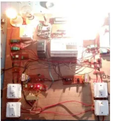
[image:5.612.250.364.577.699.2]A. No Fault Condition
Fig. 2: Experimental Setup
B. Fault Detected In Line A (Voltage Below 150Volt) And Voltage Sharing From Line B
Fig. 3: Fault detected in line A (voltage below 150v) C. Fault Detected In Line A (Over Current Fault)
Fig. 4: Fault detected in line A (over current fault)
When over current occur then, current sensor will send SMS to PLC and it creats cut off condition to load. After reset the switch it will work in intial condition.
Technology (IJRASET)
©IJRASET: All Rights are Reserved
134
VI. CONCLUSION
The electric energy produced at generating stations is transported over high voltage transmission lines to utilization points. In the early days, electric systems were operated as isolated systems with only point-to-point transmission at voltages that are considered low by today’s standards. Transmission lines should transmit power over the required distance economically and satisfy the electrical and mechanical requirements prescribed in particular cases. This system is used for over current and under voltage fault condition. There are so many devices which can withstand with voltage fluctuation for a particular time but beyond that it may damage. For protection of that device this system can be used. The choice of a device for fault consideration, best suited to particular field conditions, is not only a technical issue but also an economical one.
VII. ACKNOWLEDGMENT
I wish to express my sincere thanks and deep sense of gratitude to respected guide Prof. Devidas D. Dighe in Department of Electronics and Telecommunication Engineering of Matoshri College of Engineering and Research Centre, Nashik for the technical advice, encouragement and constructive criticism which motivated to strive harder for excellence. I also wish acknowledgement to the people who gives support direct or indirectly to the paper writing.
REFERENCES
[1] Mohsen Ghalei Monfared Zanjani, Hossein Kazemi Karegar, Hasan Ashrafi Niaki, Mina Ghalei Monfared Zanjani “High Impedance Fault Detection of Distribution Network by Phasor Measurement Units” IEEE 2013; accepted January 11th, 2013.
[2] K. Nareshkumar “Application of Multi-Agents for Fault Detection and Reconfiguration of Power Distribution System” IEEE 2008.
[3] Abhishek B. Sharma, Haifeng Chen, Min Ding, Kenji Yoshihira “Detection and Localization in Distributed Systems using Invariant Relationships” 2013 IEEE.
[4] E. Kallauer “Detection of High Impedance Faults Power Technologies” EPRI Final Report EL-2413 June 1982 Inc.
[5] Prof. M. S. Sujatha and Dr. M Vijay Kumar “On-line Monitoring And Analysis Of Fault In Transmission And Distribution Line Using GSM Technique” 30th November 2011 IEEE. Vol. 33 No.2
[6] “Upper Bounding Fault Coverage by Structural Analysis and Signal Monitoring” Soumitra Bose and Vijay Gangaram Auburn Univerity, 2006 IEEE. [7] Sudhakar M. Reddy “A Test Generation Procedure for Avoiding the Detection of Functionally Redundant Transition Faults” Electrical & Computer Eng.
Dept. Iowa City, 2006 IEEE.
[8] Irith Pomeranz “Hazard-Based Detection Conditions for Improved Transition Fault Coverage of Functional Test Sequences” School of Electrical & Computer Eng. Electrical & Computer Eng. Dept. Purdue University University of Iowa W. Lafayette, IN 47907, U.S.A 2009 24th IEEE.
[9] Irith Pomeranz “Static Test Compaction for Transition Faults Under the Hazard-Based Detection Conditions” School of Electrical & Computer Eng. Purdue University 2012 IEEE.
[10] Ankan K. Pramanick Sudhakar M. Reddy “On the Detection of Delay Faults” 1988 IEEE.
[11] Chao-Wen Tseng and Edward J. McCluskey “Multiple-Output Propagation Transition Fault Test” 2000 IEEE.
[12] Hsiung Cheng Linieee “Power Harmonics and Interharmonics Measurement Using Recursive Group-Harmonic Power Minimizing Algorithm” Transactions On Industrial Electronics, Vol. 59, No. 2, February 2012 IEEE.
[13] Ming-Ta Yang and Jyh-Cherng Gu “Optimal Coordination of Automatic Line Switches for Distribution Systems ” IEEE 2012, 5, 1150-1174; doi:10.3390/en5041150.