Technology (IJRASET)
Design, development and performance evaluation
of residual crop chipping machine
Gautam Raj Jodh1, Rajanikant Y. Mahajan2, Diwesh B. Meshram3, Nagnath U. Kakde3
1.2,3
Assistant Professor, 1.2Priyadarshini Institute of Engineering and Technology, Nagpur, India.
3
Dr. Babasaheb Ambedkar College of Engineering and Research, Nagpur, India.
Abstract—After harvesting it is customary to leave the stalks in the field as they are. Before the next cultivation season commences, these stalks get dried in the sun and are then burnt as firewood in households or burnt in the field itself. This leads to excessive pollution. These plants may be transported to various industries related to plywood, furniture, etc. where they may be put to better use. But these stalks are light in weight & high in volume. Hence it is not economical to transport them to industries for further processing. These stalks may be chipped manually and then transported, but this method is very time consuming and labor intensive. This paper is an approach to solve this problem by presenting design and development of a chipping machine. The machine provides means for quick and easy chipping of residual plant stalks thereby facilitating its transport and value addition for farmers.
Keywords—Residual crop, chipping machine, stalk cutter, particle board, feed mechanism.
I. INTRODUCTION
Rapid industrialization in India has increased the demand for wood. Particle boards are being used for table tops, partitions, etc. in lieu of wood & plywood. Raw materials used for particle boards are wood & bagas. Nowadays bagas is used by paper mills, boilers & other small scale industries as a fuel in lieu of coal since it is economical & has sufficiently high calorific value. Bagas can also be used in making compost fertilizers. Due to this, since last two years bagas prices have gone up from Rs. 900-1000 per ton to Rs. 4000-5000 per ton. So the manufacturers of particle board have turned to other raw materials like stems, shrubs, weeds of different plants like cotton, jawar, maize, etc as they are available in plenty. The chipped stalk obtained will be a better substitute to bagas. Chips may be sold to the industries for up to Rs.1500 per ton. In India, about 20 million tonnes of these stalks are generated every year. These stalks are generated in the range of 1-2 tonnes per hectare. They can be utilized as a raw material for making various value added products. Technologies are available for the processing of above mentioned products, but with a limitation of minimum plant capacities of 60-70 tonnes per day to make the unit economically viable. This vast source of lingo-cellulose mass can be utilized as a substitute to wood or timber as raw material for manufacturing various products like
Particle board
Paper and paper products Hard board
Soft boards (ceiling-tiles, pin boards, expansion joints etc.) It has following contents:-
Holo cellulose is 77% Lignin is 26% Ash is 7%.
They can be used as a raw material mainly in particle-board industries, preparation of pulp & paper, hard boards and corrugated boxes.
For stalks of cotton, jawar and maize as raw materials, a broad outline of the projects budget is stated below:-
TABLE 1: PROJECT BUDGETS
Type of Industry Minimum Viable Capacity (tonnes/day) Budget (million)
Paper/Board 55 300
Particle Board 35-45 200
Technology (IJRASET)
II. DEVELOPMENTS
Chipped residual plant stalks have the following uses as a raw material:
A. Particle Board Industry
It is a flat solid product produced by compressing small particles of wood and simultaneously bonding them with an adhesive. Its production has shown an average growth rate of 15% per annum during last decade as against a growth rate of 80% per annum for wood products & of plywood at 9% per annum. Actual demand for particle boards is expected to be 90000 tonnes, whereas the supply position is not even 75% of the demand. Hence there is a good market potential for alternatives. This process involves chipping of stalks, grinding of particles to suitable mesh size in a pulveriser, mixing with suitable binder and catalyst, adjusting the moisture content and then pressing between heated plates of a hydraulic press. Different chemicals and additives are added as per requirement to make it water proof, fire proof or termite resistant.
B. Paper and Pulp Industries
25 million tonnes of stalks of Cotton, jawar and maize are generated in India annually. In contrast to other agricultural crops residues, the stalks of these crops have fibre structure similar to that of hardwood.
The use of chipped crop stalk invoke following advantages
1) Time as well as labour saving.
2) Value addition to the farmers.
3) Transportation cost is reduced heavily.
4) Chips obtained have wider applications.
Characteristics of crop stalk are tabulated below
TABLE 2:CUTTING FORCE REQUIRED
Stem diameter (mm) Cutting force (N)
14 1600
13.5 1500
12 600
11 450
9 350
7 250
5 200
TABLE 3:STALK PROPERTIES
Moisture in soil (%) Plant Height (cm) Root Depth (cm) Stem diameter (mm)
Weight of plant (gm)
11 100 25 12 70
9.5 80 25 11 85
9.4 100 25 10 90
10.43 120 20 9 85
9.8 170 30 14 120
III. DESIGNCALCULATIONS
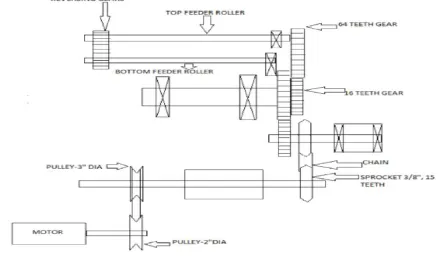
For motor with 1440 rpm and Pulley diameter as 2”, cutter roller speed is calculated as 960 rpm. Now, N1D1=N2D2 where,
Technology (IJRASET)
Thus the diameter of cutter roller pulley is 3”. Hence, 3” diameter a section single groove is provided on the roller in order to achieve 960 rpm. The 960 rpm speed to 60 rpm is reduced for the feeder roller considering the size of the machine. The reduction ratio is 16:1. This is made possible by designing a gear train consisting of 4 gears.
Two gears with 16 teeth and two gears with 64 teeth. The transmission from the cutter roller to feeder roller is depicted in the figure. Sprockets on opposite sides of the cutter roller have 3/8” pitch & 15 Teeth. From this same rpm is fed to the sprockets of same size and on the same shaft 16 teeth gear is mounted, by chain drive of 3/8” size. This 16 teeth gear meshes with 64 teeth gear which is mounted on a separate shaft. The rpm of 64 teeth gear = 960*16/64=240 rpm.
On the same shaft 16 teeth gear is mounted which will rotate at 240 rpm. This 16 teeth gear again meshes with 64 teeth gear which is mounted on top feeder roller. Hence, rpm of top feeder roller will be = 240 * 16 / 64 =60 rpm. In this way 60 rpm speed of feeder roller is achieved.
a. Reversal of Bottom Feeding Roller
The stalks are passing through 2 feeder rollers mounted one above the other with a gap of 5mm. As the stalks must advance up to the cutter roller, the feeder rollers must rotate in direction opposite to each other. For this purpose the other side of the feeder roller is used on which the gears are mounted in such a way that they engage with each other & run the system in a required direction. As the drive is given to the top roller, bottom roller rotates in the reverse direction by this gear train.
Components
The machine consists of following sub-assemblies: Cutter sub assembly.
Feed sub assembly. Support structure. Transmission system.
TABLE 4
LIST OF COMPONENTS
Sr.
no. Components Material
Cutter sub assembly
1 Cutter roller Mild steel
2 Rotating blade HCHCr
3 Shaft Alloy steel
4 Bearings UCFC 206 self-aligned type
5 Fixed blade mounting Mild steel square bar
6 Fixed blade HCHCr
Feed sub assembly
1 Feeding chute Mild steel sheet
2 Feed rollers Plain carbon steel
3 Shaft Alloy steel
4 Bearings UCFL 204 self-aligned
5 Intermediate plate Mild steel sheet
Support structure
1 Base frame Mild steel sheet
2 Support Mild steel rod
3 Chips outlet chamber Mild steel sheet
4 Safety cover Mild steel sheet
5 Handle Mild steel
Transmission system
1 Electric motor -
2 Electric motor pulley Sintered steel
Technology (IJRASET)
4 V belt Polyamide fibres embedded in the rubber
5 Sprocket Steel
6 Chain -
7 Transmission gears Cast steels
8 Reversing gear Cast steels
1) Base frame: The entire structure is welded to the base frame. Legs of frame are provided with circular M.S. plates for increasing the area of load distribution. It is further provided with rubber pads of 3 mm thickness to absorb vibrations.
2) Support structure: Dimension is 3” x 3/2”. Two M.S. plate of size are welded with M.S. Flat. M.S. plate is provided with drills for clamping and is bolted to channel frame. To maintain the parallelism between two M.S. plates, 4 M.S. tie rods of size 16x16 square are attached between the plates by bolts. Finally whole supporting structure is bolted with base frame by 6 bolts of size M 10.
3) Motor: Motor used is single phase 0.5 HP, 1440 rpm, foot mounted type. Direction of rotation is marked on the motor. Motor is provided suitable casing and 15 amp top to connect to main supply. A pulley of diameter 2” and with single groove of ‘A’ section is mounted on motor shaft.
4) Cutter roller: A Flat surface is provided on top to support rotating blade and a release groove is provided just below the blade to release chips in the chamber. It is dynamically balanced at 1200 rpm.
5) Rotating blade: It is a High carbon high chromium steel hardened to 55 BHN
6) Fixed blade mounting base: Dimension is 1”x1”. It is provided with side taps of size M8 and bolted to main plates and bottom is supported on M.S. plate.
7) Fixed blade: Three counter sunk bolts provided of size M8x 15 long to fasten the blade to the base. It has a shear cutting edge on one side which can be sharpened when it gets blunt.
8) Intermediate plate: Material is M. S. sheet. It Acts as a bridge on bottom plates welded to main plates by 4 screws
9) Feed rollers: Two feed rollers with flutes are provided and act as feed rollers.
10) Material feeding chute: Mounted using two angles welded to main frame and fastened using bolts.
11) Chip outlet chamber: Material is M.S. Sheet, 1.5” thick. It is fitted to main base and angle may be altered so that chips flow out smoothly without blocking the chamber.
12) Safety covers: M. S. sheets are provided to avoid accidents.
13) Handle: For manual operation of the chipper, handle is provided. It can be attached on driven shaft when required.
14) Transmission system: Following components are provided in the transmission system.
a) Motor pulley also called as driving pulley diameter = 2’’x1A.
b) Driven pulley mounted on cutter roller shaft diameter = 3’’x1A.
c) V belt section size.
d) Two bearings, UCFC 206, self-aligned.
e) Four bearings, UCFL 204, self-aligned.
f) Two Sprocket, 3/8’’ pitch and 15 teeth.
g) Chain.
h) Transmission gears.
i) Two reversing gears for feed roll.
IV.WORKINGPRINCIPLE
The machine consists of three basic components: fixed blade, moving blade and a feeding roller. The material i.e. dried stalks of crops e.g. cotton, maize, tur dal, jowar etc. are fed to the feeding rollers through the chutes and conveyed to fixed blade.
The rotating blade fixed on the cutter roller cuts the stalks in pieces by shearing action between the gap of fixed and rotating blade. The chips so formed fall down and come out through the outlet chamber and gets collected in the tray kept below.
The multi-crop chipping machine is constructed in the two zones: Feeding zone & Chipping zone.
Technology (IJRASET)
roller and fixed blade.
B. Chipping zone
The chipping zone includes cutter roller mounted with rotating blade and fixed blade and outlet chamber.
The material is first fed to the feeding zone then afterwards the material is transferred to the further processing operations in the chipping zone.
V. TRANSMISSIONSYSTEM
Basic components of transmission system are as follows: Motor
Gears Pulleys
Chain drives and sprockets
The power from the motor is transmitted first to cutter roller by V-belt drive on one side of the rollers. From the other side of the cutter roller the power is further transmitted to one side of the top feeder roller by means of chain drive and reduction gear train. On the other side of the top feeder roller, a gear is mounted and this gear drives the bottom roller on which a connecting gear is mounted. Thus the reversal of directions of feeder rollers is also achieved.
The design of the transmission system is illustrated below:
VI. FABRICATION
Basic steps involved in the fabrication are:
A. List of the materials.
B. Cutting of suitable materials for various components.
C. Machining these components as per the required dimensions.
D. Pre-assembly including the rollers, cutters and the intermediate plate.
E. Bolting this pre-assembly in between the cover plates.
[image:6.612.90.528.426.682.2]F. Assembling all the components on the foundation in proper manner.
Technology (IJRASET)
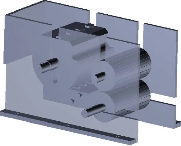
[image:7.612.100.488.74.654.2]Figure 2 (a) Cutter roller with blade (b) Support structure (c) Cutter and feed sub assembly (d) Feed roller sub assembly
Figure 3 Final assembly
REFERENCES
[1] Aji I. S*., James E., Ejovwoke A. and Mshelia D. A., 2013, Development of an electrically operated cassava slicing machine, Arid Zone Journal of
Engineering, Technology and Environment, Vol. 9, August, 2013, 90-95.
[image:7.612.159.450.396.630.2]Technology (IJRASET)
Harmonized Research, Vol. 3(2), 2015, 78-84.
[4] Oriola, K. O 1 and A. O. Raji, Trends at Mechanizing Cassava Postharvest Processing Operations, International Journal of Engineering and Technology
Volume 3 No. 9, September, 2013, 879-887.
[5] M. C. Ikejiofor, O. N. Eke-Okoro, Performance Evaluation of NRCRI Cassava Stem Cutting Machine, International journal of scientific & technology