Design and Optimization of Multiple U- slot
Microstrip Patch Antenna for Wireless Applications
1
Gulshan Rana 2Er.Saranjeet Singh 1
Student (M.Tech, ECE) 2Assistant Prof., ECE Department
Galaxy Global Educational Trust Group of Institutions, Dinarpur, Ambala,India
Abstract: Four U slot antenna is obtained by making four u slots in patch. Initially simple patch antenna is taken and four u slots are cut one by one to analyze effect. Initially single u shaped antenna is designed and results are obtained. This antenna resonates at 4.6 GHz, 6.7 GHz and 8.6 GHz with return loss of -13.7 dB, -30.7 dB, -14.30 dB, good gain of 1.38 dBi, 3.32 dBi and 2.34 dBi and bandwidth of 150 MHz, 1200 MHz and 250 MHz at 4.6 GHz, 6.7 GHz and 8.6 GHz. This antenna can be useful for different applications in C band, WLAN, Defence and secure communication and IMT band. Design and simulation has been carried out using IE3D.
I. INTRODUCTION
One of fast growing segment of communication industry is wireless communication which finds application in many areas. Radio waves and microwaves play an important role in daily life. Television signals are transmitted by satellite using microwaves, military uses microwave for surveillance and navigation purposes. Telephone and data signals are transmitted by microwaves. A wireless system is combination of active and passive devices. The entire radio frequency spectrum is subdivided into different bands and each band has different applications. Hence this will avoid interference and allows efficient use of radio spectrum. Microwave spectrum is usually called as electromagnetic spectrum, since it range from 1GHz to 100 GHz. Microwave bands are classified into many frequency bands. Since most common applications are within 1GHz to 40 GHz. Hence different bands within this range are L band (1-2 GHz), S band (2-4 GHz), C band (4-8 GHz), X band (8-12 GHz), Ku band (12 -18 GHz), K band
(18-26.5 GHz) and Ka band (26.5-40 GHz). Different bands
together with their applications are mentioned in table 1.1. Microstrip antenna finds applications from 1 GHz to 12 GHz. Hence microstrip antenna can be designed for L band, S band, C band and X band applications.
II. ANTENNA DESIGN
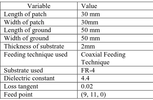
[image:2.612.339.583.519.679.2]Since there are several disadvantages of microstrip patch antenna, hence to overcome them different techniques like fractal geometry, DGS and slot cutting on patch can be used. Slots have been cut on side of patch so as to obtain better characteristics, Initially patch of length 30 mm is taken and analyzed using coaxial feed at (9, 11, 0). FR-4 has been used as substrate with dielectric constant of 4.4 and loss tangent of 0.02. Design is modified by making a u slot so as to make similar to that of reference antenna. As there are certain draw backs of microstrip antenna, hence one will use such techniques. Dimensions of antenna are shown in table 1.
Table 1: Dimensions of Initiator Antenna
Variable Value
Length of patch 30 mm
Width of patch 30mm
Length of ground 50 mm
Width of ground 50 mm
Thickness of substrate 2mm
Feeding technique used Coaxial Feeding
Technique
Substrate used FR-4
Dielectric constant 4.4
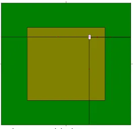
In this design configuration square patch is taken having dimensions of 30 mm. Ground plane is having dimensions of 50 mm. Design of zeroth iteration has been shown in figure 1. Feed can also been used as microstrip line but coaxial; feed has been used so as to obtain better impedence matching.
Figure 1:Initiatior Antenna
[image:3.612.95.227.188.316.2]After designing basic configuration, one may also get simple u slot to obtain better characteristics. In case of reference antenna one has patch of size 32X 30 mm2. Instead of designing antenna with same dimensions as that of antenna one cut u slot in patch of size 30 mm. U slots cut in patch is having length of 6 mm and two mm wide. Two straight arms are surrounding it with dimensions of 1x 8 mm2. This combine forms u slot patch. By applying u slot to patch characteristics shows improvement. This antenna has fed by coaxial feed at feed point (13, 0). Geometry correspond to it is shown in figure 2.
Figure.2:U slot cut Patch Antenna.
Ground plane is having dimensions of 50 mm with FR-4 as thickness of 2mm. Size of limbs remain same as shown in figure 2, but difference is that. Number of u slots increased from one to four as shown in figure 3.
Figure3:Four u- slot Patch Antenna
Feed to antenna has been given at feed point of (13, 1, 0). By analyzing this geometry one may find to get good results. Apart from using coaxial feeding technique, one can also use microstrip line feeding technique. It is found that by applying DGS performance of antenna increases, DGS is made by cutting any shape on ground plane. By applying different DGS to antenna, performance of antenna increases. In this papereffect of applying different iterations of fractal geometry are applied but parametric analysis can be done by changing feed point, thickness of substrate, DGS and feeding technique.
III. RESULTS AND DISCUSSIONS
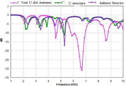
[image:3.612.32.275.469.682.2]Figure 4: Return Loss Vs. Frequency for Multi U Slot Antenna
Different characteristics of antenna are represented by different colored lines as shown in figure 4. Square patch fed by coaxial feed resonates at 5.3 GHz with return loss of -16.5 dB, gain of 1.77 dBi and bandwidth of 30 MHz. By applying single u slot to patch return loss of antenna increased but rest of characteristics of antenna improves slightly. Initiator antenna resonates at 5.3 Ghz with return loss of -11.20, gain of 3.23 dBi and bandwidth of 50 MHz. By applying geometry in which four u slots are cut out, antenna resonates at four bands. It was found that by cutting number of slots, antenna shows improvement in characteristics as this antenna resonates at 4.6 GHz, 6.7 GHz and 8.6 GHz with return loss of -13.7 dB, -30.7 dB, -14.30 dB. This antenna has good gain of 1.38 dBi, 3.32 dBi and 2.34 dBi. As number of cuts increased, bandwidth of antenna improved as this antenna had bandwidth of 150 MHz, 1200 MHz and 250 MHz at 4.6 GHz, 6.7 GHz and 8.6 GHz.
(a) (b)
[image:4.612.51.270.114.263.2](c)
Figure 5: Radiation Pattern of Multi U slot Antenna at (a) 4.6 GHz, (b) 6.7 GHz and(c) 8.6 GHz
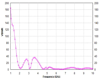
This antenna is highly directive antenna with large directivity. Radiation pattern of antenna at different frequencies namely 4.6 GHz, 6.7 GHz and 8.6 GHz have been shown in figure 5(a), 5(b) and 5(c). Table 5.1 shows comparison of results of different designs of making u slots cut applied on rectangular patch to form four u slot antenna as shown in figure 1, 2 and.3. When a transmitter is connected to an antenna by a feed, the impedance of the feed line and antenna must exactly match for maximum energy transfer from the feed line to the antenna. However, when the antenna and feed line do not have matched impedances, part of the electrical energy cannot be transferred from the feed line to the antenna. It is the function of reflection coefficient and tells amount of power that gets reflected. VSWR of antenna as shown in figure 3 is shown in figure 6. Results are analyzed in terms of antenna paramameters as shown in table 2.
Table 2: Comparison Results of Different Antenna Confuigration of u slot patch
Iteration Number Resonanc e Frequency (GHz) Return Loss (dB) Gain (dBi ) Directivit y (dBi) Band width (MHz) 0th Iteration
5.3 -16.5 1.77 8.94 30
initiator 5.3 -11.20 3.23 7.86 50
double 4.6 -13.7 1.38 5.87 150
6.7 -30.7 3.32 6.73 1200
Figure 6: VSWR Versus Frequency for U Slot Microstrip Antenna
Smith chart was invented by P.H Smith of Bell Laboratories in 1939. It is most useful tool for high frequency circuit applications. Smith chart of double wang shaped antenna is shown in figure 7.
Figure 7: Smith Chart for U slot Microstrip Patch Antenna
It is best method of representing complex impedance with respect to coefficients defined by the reflection coefficient. For analyzing impedance, admittance and for solving transmission line problems, Smith chart is an important tool.
From above analysis, it is clear that as number of cuts increase, characteristics of antenna improved. Further characteristics can improve by use of DGS
IV. CONCLUSION
Four U slot antenna is obtained by making four u slots in patch. Initially simple patch antenna is taken and four u slots are cut one by one to analyze effect. Initially single u shaped antenna is designed and results are obtained. This design is modified by cutting four u slots to form u slot ring like structure. Parametric analysis has been done. It is found that when no DGS is applied bandwidth of antenna was small. This antenna resonates at 4.6 GHz, 6.7 GHz and 8.6 GHz with return loss of -13.7 dB, -30.7 dB, -14.30 dB, good gain of 1.38 dBi, 3.32 dBi and 2.34 dBi and bandwidth of 150 MHz, 1200 MHz and 250 MHz at 4.6 GHz, 6.7 GHz and 8.6 GHz. This antenna can be useful for different applications in C band , WLAN, Defence and secure communation and IMT band.
REFERENCES
[1]
Kakkar S., Priyadarshini andRaniS., 2013. “New Antennawith Fractal Shaped DGS for Emergency Management Applications”, International Journal of Advanced Research in Computer Science and Software Engineering,Vol. 3, Issue 3, pp 721-724.
[2]
Kumar A., Kaur J. and Singh R., 2013. “Performance Analysis of Different Feeding Techniques”, International Journal of Emerging technology and Advanced Engineering”, Vol. 3, Issue 3, pp 884-890.[3]
Moghadasi M. Naser, Sadeghzadeh R. A., Fakheri M., Aribi T., Sedghi T. and Virdee B.S., 2012. “MiniatureHook-Shaped Multiband Antenna for Mobile
Applications”, IEEE Letters on Antennas and Wireless Propagation,Vol. 11, pp 1096-1099.
[4]
Sun Xu-Bao, Cao Mao-Yong, HaoJian-Jun and GuoYin-Jing, 2012. “A rectangular slot antenna with improved bandwidth”, International Journal of Electronics and Communications, Elsevier, Vol. 66, pp 465-466
and E-Shaped Patch Antennas” IEEE Letters on Antenna and Wireless Propagation, Vol. 11, pp. 1474-1477.
[6]
Chitra R. J., Sganya, A. and Nagarajan V.,2012.“Enhanced Gain of Double U-Slot Microstrip Patch Antenna Array for WiMAX application” Proceedings ofIEEEInternational Conference on Communications and Signal Processing (ICCSP),Chennai, India,pp. 141-144.
[7]
Mirzamohammadi F., Nourinia J. and Ghobadi, C.,2012.“A Novel Dual-Wideband Monopole-Like Microstrip Patch Antenna with controllable frequency Response”
IEEE Letters on Antenna and Wireless Propagation,
Vol.11, pp. 289-292.
[8]
Liu Wen-Chung, Wu Chao-Ming and Dai Yang, 2011.“Design of Triple Frequency Microstrip Fed Monopole Antenna Using Defected Ground Structure”, IEEE Transactions on Antennas and Propagation, Vol. 59, No. 7, pp 2457-2463.
[9]
Arya A. K. and Patnaik A. and Kartikeyan M.V., 2011. “Microstrip Patch Antenna with Skew-F Shaped DGS forDual Band Operation”, Progress in Electromagnetic Research M., Vol. 19, pp 147-160.
[10]
Mutiara. A. B, Refianti. R, Rachmansyah, 2011. “Designof Microstrip Antenna for Wireless Communication at 2.4 GHz”, Journal of Theoretical and Applied Information Technology, Vol. 33, No.2, pp 184-192.
[11]
Vazquez C., Hotopan G., VerHoeye S., Fernandez M., Herran L.F. and Las-Heras F.,2010. ”Defected ground Structure for Coupling Reduction between Probe FedMicrostrip antenna Elements” Progress in
Electromagnetics Research proceedings, pp. 640-644.
[12]
Koohestani M. and Golpour M., 2010. ”U-shapedMicrostrip Patch Antenna with Novel Parasitic Tuning stubs for UWB Applications” IET Microwaves, Antenna and Propagation, Vol. 4,pp. 938-946.