© 2018, IRJET | Impact Factor value: 6.171 | ISO 9001:2008 Certified Journal | Page 3708
Study on Compressive Membrane Action in Slab at Edge and Corner
Column in a Continuous Reinforced Flat Slab
Nithin.V
1, Deepa Varkey
21
P.G Student, Mar Athanasius College of Engineering, Kothamangalam, Kerala, India
2Assistant Professor, Mar Athanasius College of Engineering, Kothamangalam, Kerala, India
---***---Abstract -
The slabs are relatively thin structural elements,whose main function is to transmit the vertical loading to their support. Flat slab is a reinforced concrete slab supported directly by concrete column without the use of beam
.
The main failure in flat slab is punching failure, which is brittle and sometimes can lead to a progressive collapse of the building. This brittle failure was examined by many researchers in the form of tests, analytical models, and FEA but in these experiments, isolated slab was considered, representing a slab-column connection limited by the line of contra-flexure for radial moment. All these isolated tested slabs had no restraint for lateral in-plane movement and they were simply supported around the edges. These test results were the basis of design codes’ design methods for punching shear resistance of flat slabs. However, the in-plane restraining forces creating the compressive membrane action in the concrete slabs were ignored. In this paper continuous FEA models were modeled and analyzed in ABAQUS and compared with tested isolated column slab connection. In addition to that a real floor system also modeled and analyzed in ABAQUS and compared with codal provision. After the numerical analysis, it is concluded that the punching shear capacity of a continuous slab is higher than the capacity of a conversional isolated slab. This FEA models can be useful for further future studies in flat slab.Key Words: Flat Slab, Punching Shear, Compressive membrane action, ABAQUS, FEM.
1. INTRODUCTION
Reinforced concrete slabs are one of the important elements in most structural systems and are largely employed in engineering practices in a variety of situations and applications. The slabs are relatively thin structural elements, whose main functions are to transmit the vertical loading to their supports. Flat slab is defined as one sided or two-sided support system with shear load of the slab being concentrated on the supporting columns. The advantages of applying flat slabs are many like depth solution, flat soffit and flexibility in design layout. Even though building flat slabs can be an expensive affair but gives immense freedom to architects and engineers the luxury of designing. The main cause of failures in flat slab is punching shear failure. It is sometimes causes progressive collapse of the building. Many researchers are performed investigation on this brittle failure in the form of experimental tests, analytical model and FEA.
In these experiments, isolated slabs were considered[1-4], representing a slab-column connection limited by the line of
contra-flexure for radial moments, which become zero at a distance approximately 0.22L, where L is the centre-to-centre span between the columns. All these isolated tested slabs had no restraint for lateral in-plane movement and they were simply supported around the edges. These test results were the basis of design codes’ design methods for punching shear resistance of flat slabs. However, the in-plane restraining forces creating the compressive membrane action in the concrete slabs were ignored.
Leila Keyvani [6] investigated compressive membrane action in progressive collapse resistance of RC flat plates and Einpaul [7] conducted analytical study on the influence of compressive membrane action on punching strength of flat slabs and came to the conclusion that the punching shear strength of flat slab was enhanced by the development of compressive membrane forces.
The most of the researchers performed experimental work and proposed empirical equations that are the basis for the current codal design approach for punching shear. In modern research in structural engineering, finite element analysis (FEA) is essential for supplementing experimental research in providing insights into structural behaviour. This paper mainly aims to investigate the compressive membrane action and its effect in punching shear on continuous flat slabs by finite element analysis.
1.1 Punching Shear Failure
Punching shear failure in reinforced concrete flat slabs occurs due to the development of a three dimensional state of stresses that is created by the high transverse stresses around the column and the in-plane stresses[5]. Inclined cracks are created inside the slab, which then propagate and form a major inclined crack. When this crack reaches the compressive zone, a punching shear cone around the column is formed leading to punching shear failure. Punching failure is brittle and sometimes can lead to a progressive collapse of the building.
© 2018, IRJET | Impact Factor value: 6.171 | ISO 9001:2008 Certified Journal | Page 3709 1.2 Compressive Membrane Action
In continuous reinforced concrete slabs, the tensile strains at the mid-depth of a slab lead to an expansion of the slab, creating horizontal displacements. These mid-depth tensile strains are the result of concrete material nonlinearity. However, the lateral stiffness of the columns opposes this expansion by imposing compressive membrane forces (in-plane restraining forces). The effect of this phenomenon, that is called compressive membrane action, is the increase of the flexural and the shear capacity of a slab [5].
Fig -1: Compressive Membrane Phenomenon
2. FINITE ELEMENT MODELLING
With the advances in modern computing techniques, finite element analysis has become a practical and powerful tool for engineering analysis and design. In Structural Engineering, development of structural design code equations or redeveloping them is a continuous process and requires a wide range of experimental studies. Performing many number of experiments is costly, time consuming and hence uneconomical. On the other hand conducting experiments is a compulsion for the research to progress. In this paper, three dimensional nonlinear finite element analyses (FEA) are presented that are applied to simulate continuous slabs and then to compare their behavior with the isolated slab test results. In this work, the ABAQUS software [11] is used with the simulation of the concrete material done using the concrete damaged plasticity model. Genikomsou AS, and Polak MA[1] has previously examined the punching shear failure by calibrating concrete damage plasticity model on the interior concrete slab(SB1). In this paper, the isolated specimen SB1 is analyzed as continuous; using different boundary conditions. Then the analysis of the whole floor system, from which the SB1 specimen has been taken, is also simulated and analyzed. FEA results of all these slabs are compared to the test results, and the discussion is provided. Finally, discussion based on the codal provisions for punching shear and comparison with the numerical results of the continuous slabs is presented.
The material and model parameters can be found from Genikomsou AS [1] & Aikaterini S [5]. Fig. 2 illustrates the compressive behavior of concrete for the slab SB1, as it was modeled in ABAQUS using the Hognestad type parabola. The tensile stress-strain relation of concrete is presented in Fig. 3. The bilinear tension softening response in terms of
stress-displacement was defined based on the fracture energy of concrete that represents the area under the stress-displacement curve. Table 1 presents all the needed material and plasticity parameters of the concrete damaged plasticity model for the numerical simulations.
Fig -2: Uniaxial Compressive Stress Strain Graph of Concrete
Fig -3: Uniaxial Tensile Stress Strain Graph of Concrete
Fig -4: Bilinear Stress Strain Graph of Steel Reinforcement Table -1: Material Properties of Concrete Damage
Plasticity Model
f'c [MPa] 44
f't = 0.33√f'c [MPa] 2.2
Ec = 5500√f'c [MPa] 36483
Esec = 5000√f'c [MPa] 33166
[image:2.595.359.507.152.275.2] [image:2.595.52.273.224.323.2] [image:2.595.350.511.308.443.2] [image:2.595.350.509.485.616.2]© 2018, IRJET | Impact Factor value: 6.171 | ISO 9001:2008 Certified Journal | Page 3710
f't = 0.33√f'c [MPa] 2.2
lc [mm] 20
Dilation angle (degrees) 40
Ɛ 0.1
Gf 0.082
σ bo/σ co 1.16
Kc 0.667
µ = 0
ʋ = 0
[image:3.595.66.258.76.236.2]Damage was introduced in concrete damaged plasticity model in tension and compression. Concrete damage was assumed to occur in the softening range in both tension and compression. In compression the damage was introduced after reaching the peak load corresponding to the strain level, Ɛ0. The reinforcement was modeled with a bilinear strain hardening yield stress-strain curve as it is shown in Fig. 4. The Young’s modulus is taken as 200,000 MPa and the Poisson’s ratio 0.3.
For modeling the concrete, three dimensional 8-noded hexahedral elements with reduced integration (C3D8R) were with 20 mm mesh size. For modeling the flexural reinforcement, three dimensional 2-noded linear truss (T3D2) elements were used and the embedded method was considered simulating the concrete reinforcement interaction. Due to the symmetry, one quarter of the tested slab was simulated and simple supports (constraining only the loading direction) were applied in the numerical model. Quasi-static analysis in ABAQUS/Explicit performed by introducing velocity through the column stub till failure. The FEA results compared to the test results, were found to be in good agreement
2.1 Modelling of Continuous models
The previously calibrated specimen SB1 is investigated as continuous by using two continuous models from Slab-column connection SB1 tested by Adetifa and Polak[3].
a. Continuous model 1
Fig -5: Continuous model 1
The supports, which are restrained in both horizontal and vertical restraints (pinned supports) at the locations of the lines of the contra flexure in order to provide lateral restraints and simulate the continuous scenario (Fig.-5).The lateral restraints are applied not only at the bottom of the
slab but also at the whole height of the slab. Fig.-8 and 9 shows the Geometry, Boundary conditions and Mesh generation of the continuous model 1.
b. Continuous model 2
Fig -6: Continuous model 2
Considering specimen’s symmetry, one quarter of the model is used for simulation. The slab is modeled with dimensions 6000 mm (1.6L) and simple supports are introduced at distance 1500(0.4L) mm and at 5625 mm(1.5L) (Fig.-6), where L denotes the center-to-center span of the slabs (L = 3750 mm). This model is based on the bending moment diagram of a floor system simulating the zero moments with the support conditions. The material properties and arrangements reinforcement of previously analyzed Isolated SBI is used for this continuous model.Fig.-10 and 11 shows the Geometry, Boundary conditions and Mesh generation of the continuous model 2.
Fig -7: Geometry and Boundary Conditions of Continuous Model 1
[image:3.595.322.539.144.232.2] [image:3.595.310.560.417.563.2] [image:3.595.309.557.607.745.2] [image:3.595.122.209.621.674.2]© 2018, IRJET | Impact Factor value: 6.171 | ISO 9001:2008 Certified Journal | Page 3711 Fig -9: Geometry and Boundary Conditions of Continuous
[image:4.595.36.294.76.230.2]Model 2
[image:4.595.291.549.77.495.2]Fig -10: Mesh Generation of Continuous Model 2 2.1.1 Comparison between Isolated model and continuous models
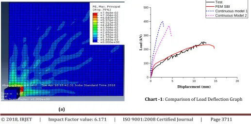
Fig – 11 shows the crack patterns formed at the tension side of the slab models with different boundary conditions and Chart -1 shows corresponding Load deflection graph.
(a)
(b)
(c)
Fig -11: a) Crack Pattern of Isolated Slab, b) Continuous Model 1, c) Continuous model 2
0 5 10 15 20
0 100 200 300 400 500
Load (k
N)
Displacement (mm)
Test FEM SBI
Continuous model 1 Contnuous Model 2
[image:4.595.36.291.267.431.2] [image:4.595.34.552.542.798.2]© 2018, IRJET | Impact Factor value: 6.171 | ISO 9001:2008 Certified Journal | Page 3712 Table -2: Comparison of Experimental and FEA Results
Specimen Failure Load (kN) Displacement at Failure (mm)
Isolated 259 11.9
Isolated FEA 233 13.7
Continuous model 1 403 2.75
Continuous model 2 369 3.25
The experimental and numerical results of isolated simply supported slab are compared with the load deflection response of FE analysis. The methods representing continuity incorporated in the analysis shows an increase in failure load while a decrease in ductility when compared with FE results in conventional slab. In particular, the Table 2 shows analysis results in terms of failure load and displacement for all specimens. The ultimate load of the continuous model 1 is increased by approximately 72% and the ultimate load of the continuous model 2 is increased by approximately 58%, both compared to the numerical results of the isolated simply supported slab.
The crack patterns developed at the tension side of the analyzed continuous slabs at failure are presented in Fig-11. In continuous slabs the crack propagation is concentrated around the column and not spread to the supports, as it happens in the isolated slab. Hence it can be concluded that the deflection in the continuous slabs have smaller compared to isolated slab. This smaller deflection leads to smaller crack width and thus to larger punching shear capacity.
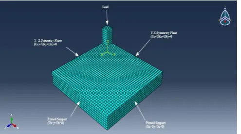
2.2 Modelling of Whole floor system
The punching shear capacity of a real slab is not the same as the capacity of the simply supported isolated slab. The whole floor system is considered from which slab SB1 is taken and analyzed by finite element method. Due to the symmetry one quarter of the whole slab is considered and the boundary conditions provided are shown in Fig-12. The columns are restrained at bottom and high uniformly distributed factored load of 18.5kPa is applied over the slab due to the high percentage of flexural reinforcement. The punching shear load of the slab is measured as the reaction at the bottom of the column, where the boundary conditions are applied.
Fig -12: Geometry and Boundary conditions of Whole Floor System
3. RESULT AND DISCUSSION
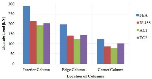
[image:5.595.40.284.101.198.2]Chart -2: Comparison of ultimate load between Test, FEA and Design Codes
Table -3: Comparison of ultimate load between Test, FEA and Design Codes
Comparing the result from the FEA with the design codes (Chart-2), it can be noted that the design codes are underestimate the punching shear capacity of slab in all conditions. The Table.3 shows, the ultimate punching shear load of the slab by analyzing the whole floor system is equal to 288kN at interior column, it is 24% higher than the load of the simply supported isolated slab. At edge column condition,
Slab Specimen results Test FEA IS 456 ACI EC2
SB1 Isolated 259 233 215 192 202
SB1 Continuous 1 - 403 215 192 202
SB1 Continuous 2 - 369 215 192 202
Whole floor –
Interior Column - 288 215 192 202
Whole floor –
Edge Column - 196 141 125 144
Whole floor-
[image:5.595.309.557.312.441.2]© 2018, IRJET | Impact Factor value: 6.171 | ISO 9001:2008 Certified Journal | Page 3713 the FEA gives a punching shear load 30-56% higher than
result provided by the design codes and in the case of corner column it is 20-57%.
In continuous model 1, IS 456 predicts an ultimate punching shear load about 46% less than the FEA load and ACI & EC2 underestimate the FEA load about 52.25% and 49.9% respectively. If we compare the continuous model 2 the IS 456, ACI and EC2 design codes are underestimate the FEA punching shear load about 41.73%, 47.97% & 45.26% respectively. Thus, the punching shear design provisions that are based on test results of isolated slabs are conservative and modifications accounting the membrane action effect can be taken into consideration. Comparing the results between the design codes, it can be said that IS 456 and EC2 gives higher punching shear resistance for all slabs, compared to the predictions that ACI provides.
4. CONCLUSIONS
The finite element method can be effectively used for evaluating punching shear capacity of continuous floor slab system. The model is calibrated with the isolated test data and with different boundary conditions. The concrete damage plasticity model in ABAQUS accurately predicts the response in isolated and continuous slabs.
The deflections of all continuous specimens are lower compared to the isolated simply supported slab because of the membrane action effect. Accordingly the continuous specimens have smaller crack widths and which are concentrated around the area of the column without spreading to the support of the slabs. So, the continuous slabs have higher punching shear strength.
The analytical results of the whole floor slab system shows that, it has a punching shear resistance capacity of about 24% higher than the strength of the simply supported isolated slab. At edge column condition, the FEA gives a punching shear load 30-56% and 20-57% higher than results provided by the design codes respectively.
The design codes do not consider the membrane action effect for the provision of punching shear in flat slabs. The finite element analysis will give comparatively accurate results considering the effect of membrane action in flat slab. Finite element analysis done in the isolated specimens can be extended using the appropriate dimensions and boundary conditions in order to simulate and analyze the same slabs as continuous. These results can be helpful in future code developments.
ACKNOWLEDGEMENT
The authors are grateful for the academic and technical support that has been provided by the Department of Civil Engineering, Mar Athanasius College of Engineering, Kothamangalam, Kerala, India. We would also express our honest gratitude to Mr. Fahd Aslam, PhD Student Department of Civil Engineering, King Saud University,
Riyadh, Mr. Eko Saputra, PhD Student Indonanesia and Mr. Khalil Essaadaoui, PhD Student, University Hassan II Casablanca Morocco for their constant technical guidance, valuable suggestions and encouragement throughout the work.
REFERENCES
[1] Genikomsou AS, Polak MA. “Finite element analysis of punching shear of concrete slabs using damaged plasticity model in ABAQUS”, Eng Struct., Vol. 98 (4), pp 38–48. 2015.
[2] Genikomsou AS, Polak MA. “Finite element simulation of concrete slabs with various placement and amount of shear bolts”, Procedia Engineering, Vol. 193, pp 313– 320. 2017.
[3] Adetifa B and Polak MA, “Retrofit of Slab Column Interior Connections Using Shear Bolts”, ACI Strut. Vol. 102(2), pp 268-74, 2005.
[4] Kinnunen S, Nylander H. “Punching of concrete slabs without shear reinforcement”, Transactions 158. Stockholm: Royal Institute of Technology, 1960.
[5] Aikaterini S. Genikomsouand Maria Anna Polak, “3D Finite Element Investigation of the Compressive Membrane Action Effect in Reinforced Concrete Flat Slabs”, Eng Struct, Vol. 136, pp 233-44, 2017.
[6] Keyvani L, Sasani M and Mirzaei Y, “Compressive Membrane Action in Progressive Collapse Resistance of RC Flat Plates”, Eng Struct., Vol. 59, pp 554–64, 2014.
[7] Einpaul J, Fernandez Ruiz M and Muttoni A, “Influence of Moment Redistribution and Compressive Membrane Action on Punching Shear Strength of Flat Slabs”, Eng Struct., Vol. 86(4), pp 33–42, 2015.
[8] ASCE-7. Minimum design loads for buildings and other structures. American Society of Civil Engineers, SEI/ASCE-7, 2010.
[9] Choi HJ, Krauthammer T. “Investigation of progressive collapse phenomena in a multi-story building” . In: Eleventh international symposium on the interaction of the effects of munitions with structures, Mannheim, Germany, 2003.
[10] ABAQUS Analysis user’s manual 6.14. Providence (RI, USA): Dassault Systems Simulia Corp.; 2014.
[11] European Committee for Standardization: Eurokod 2: Design of concrete structures - Part 1-1: General rules and rules for buildings, (2004) pp. 225.
[12] ACI Committee 318: Building code requirements for structural concrete and commentary (ACI 318-14), (2014) pp. 525.