A Monthly Double-Blind Peer Reviewed Refereed Open Access International e-Journal - Included in the International Serial Directories.
GE-International Journal of Engineering Research (GE-IJER) ISSN: (2321-1717)
86 | P a g e
GE-International Journal of Engineering Research
Vol. 4, Issue 6, June 2016 IF- 4.721 ISSN: (2321-1717)
© Associated Asia Research Foundation (AARF) Publication
Website: www.aarf.asiaEmail : [email protected] , [email protected]
LDPC CODES FOR ERROR CONTROL IN OPTICAL DISCS
Kumar Khandagle1, Anil Durgude2, Pradeep Singh3, Jayant Darade4
1,2,3,4
Department of Electrical Engineering,
Veermata Jijabai Technological Institute, Matung, India.
ABSTRACT
Low Density Parity check codes are belong to class of Linear block codes which
possesses burst error correction capabilities.[1] LDPC codes are Shannon Channel Capacity
approaching codes and more superior as compared to competitive Turbo Codes at High Data
rates both due to Low error floor as well manageable decoder complexity. Compact Disc is a
Digital optical disc data storage format which was originally developed for transfer Music
around the world. Various other data formats are developed to suite particular user need and
now some format possesses capability of rewriting data. Data is stored in the form of Pits
and Lands. A light falling on pits and lands of different height results in difference in
intensity of reflected light which is captured by Photodiode. Intensity of reflected light on Photodiode is manipulated as zero or one and data stored is recovered. CD’s are susceptible
to damage during Handling and exposure to environmental conditions which destroy data
stored in CD. With development of powerful Error control codes, error due to scratches and mishandling of CD’s can be corrected to some extent and precious data can be recovered. In this paper we utilized LDPC codes for error detection and error correction in CD’s.
Implemented architecture is tested on Xilinx ISE software and test results are generated by
Xilinx ISIM software.
A Monthly Double-Blind Peer Reviewed Refereed Open Access International e-Journal - Included in the International Serial Directories.
GE-International Journal of Engineering Research (GE-IJER) ISSN: (2321-1717)
87 | P a g e 1. INTRODUCTION
Channel codes play a prominent role in the development of communication. Channel
codes made possible some of the most challenging applications like Deep space
communication, Wireless communication under Harsh environmental conditions etc. The
Major advantage of employing Channel codes is to achieve communication at lower Power as
compared to those without Channel codes which greatly reduces the size of transmitters and
Antennas. Two Major classes of Channel codes are Convolutional Codes and Linear Block
codes. Linear Block codes possesses distinct advantage of simplicity in Implementation of
both Encoder and Decoder. Low Density Parity check codes belong to the class of linear
Block codes in which 1's present in parity matrix are very less as compared to number of 0's
hence named as low density.
2. ENCODING
Encoding of LDPC codes begins with Generator matrix which is obtained from
H-matrix by performing some row and column operations. Encoded Codeword is obtained by
following Equation. Message bits are taken in the form of row matrix which are multiplied
with Generator matrix to obtain Encoded codeword.
C = m x G
Where,
M is Message bit row matrix of dimension 1 x k,
G is Generator matrix of dimension k x n,
C is Encoded Codeword of dimension 1 x n.
Since, We are working on Digital data Multiplication become equivalent to AND operation
and Addition become equivalent to XOR operation.
3. DECODING
Decoding is obtained by H-matrix. Received codeword is multiplied with the
transpose of H-matrix and if the result is all zero row matrix then Codeword received is
correct. Finally Message bits and parity bits are separated and Information bits are stored.
If multiplication of the transpose of the H-matrix and the Received codeword does not
produce all zero row matrix then Codeword is found to be in error. As soon as the error is
A Monthly Double-Blind Peer Reviewed Refereed Open Access International e-Journal - Included in the International Serial Directories.
GE-International Journal of Engineering Research (GE-IJER) ISSN: (2321-1717)
88 | P a g e
decode correct received bits. Decoding algorithm is classified into two classes Hard decoding
algorithm and soft decoding algorithm. Hard decoding takes received message bits and
predict expected message bits on the basis of parity bits appended in the generation of
codeword whereas soft decoding algorithm use probabilities to predict expected message bits.
Since Decoding of message bits in Hard decoding algorithm depends on receiving codeword
bits they are more prone to error as compared to soft decoding algorithms. Bit flipping
Decoder belongs to class of Hard Decoder. Sum product algorithm belongs to class of Soft
decoder.
Message bits from received codeword is obtained by relation,
D = C x HT
Where,
D represent Decoded Message bits,
HT represent transpose of H-Matrix.
4. ENCODING ARCHITECTURE
The Information bits are taken in serial form to save number of I/O pins. We have design
Codeword generator which requires nine message bits and gives out twelve bit codeword
appending three parity bits for efficient decoding at receiver. Since input is taken serially one
bit at time we require nine clock cycle to start encoding so Serial message bits are
temporarily stored and up counter is used to generate enable signal to processor whenever its
count reaches to nine so that Codeword Generator will operate correctly. Instead of Memory
we can also use 9-bit Serial in Parallel out shift register which takes information bits and pop
out result after nine clock cycle but then next message have to wait for nine clock cycles
which will lead to bottle neck problem which can be removed by providing temporary
memory in front of shift register. Output of Serial input parallel output is given to codeword
processor which generate encoded codeword. Codeword Processor is sub system consisting
of AND Gate and XOR Gate array to generate codeword. Processor is provided with Internal
memory to store temporary result. Counter is 4-bit Up counter with Nine states, it counts
A Monthly Double-Blind Peer Reviewed Refereed Open Access International e-Journal - Included in the International Serial Directories.
GE-International Journal of Engineering Research (GE-IJER) ISSN: (2321-1717)
[image:4.595.207.391.39.185.2]89 | P a g e
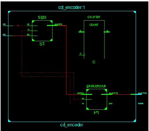
FIG 4.1 : PIN DIAGRAM OF CD ENCODER.
FIG 4.2 : RTL SCHEMATIC OF CD ENCODER.
Pin diagram show ‘ein’ pin which is used to start Encoding. Entire system is
sequential Machine hence every process is synchronized with Clock signal. ‘eout’ is 12-bit
Ouptut bus through which encoded data is given which can be written on Compact Disc.
5. DECODER ARCHITECTURE
Decoder is used to recover Information bits from received codeword. Our Decoder
works on Bit flipping algorithm which belongs to class of Hard decoder. Predictor is heart of
entire system which take single bit from received codeword and generate two temporary bit
for each bit depending on Tanner graph. The two bits from Predictor and received bit is then
feed to Maximum likelihood decoder. Since our system works on 12-bit received message,
we require twelve Maximum likelihood decoder. Maximum likelihood decoder consist of
[image:4.595.178.418.225.435.2]A Monthly Double-Blind Peer Reviewed Refereed Open Access International e-Journal - Included in the International Serial Directories.
GE-International Journal of Engineering Research (GE-IJER) ISSN: (2321-1717)
90 | P a g e
from predictor is applied to two pins, output of Maximum likelihood decoder represent
decoded bit for single bit of received codeword.
5.1 PREDICTOR
Predictor play crucial role in decoder system. Below figure shows typical Tanner
graph plotted from H-matrix. Diamond block represent message bits given to predictor and
square block used to generate output bits of predictor. Two bits for ‘m1’ generated by
predictor by equation as given below. Temp1 and temp2 represent output equation used by
predictor.
Temp1 = m2 XOR m3
[image:5.595.157.429.236.448.2]Temp2 = m2 XOR m4
FIG 5.1 TYPICAL TANNER GRAPH
[image:5.595.175.421.494.691.2]A Monthly Double-Blind Peer Reviewed Refereed Open Access International e-Journal - Included in the International Serial Directories.
GE-International Journal of Engineering Research (GE-IJER) ISSN: (2321-1717)
91 | P a g e
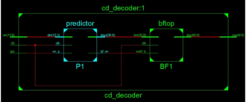
Pin diagram of CD decoder shows various input on output pins. ‘cin’ is pin through
which 12-bit received message bit is given to Decoder. ‘cout’ is decoded bit or information
[image:6.595.94.504.105.275.2]bit generated iteratively by Bit flipping Processor.
FIG 5.3 : RTL SCHEMATIC OF CD DECODER
RTL schematic show various sub system. Received codeword is stored temporarily to
latch before giving to predictor. Bits from predictor are further applied to bit flipping
Processor which takes 27 input bits and gives 9-bit output which represent Decoded message
bits.
6. CONCLUSION
LDPC Codes are error correcting codes with amazing burst error correction
capabilities. The method to embedding LDPC System with CD writer and reader is discussed.
Implemented architecture discussed systematic method to implement LDPC system working
on Hard decoder on FPGA platform.
References
[1]R. G. Gallager, Low-Density Parity-Check Codes, Cambridge, MIT Press, 1963.
[2] R. M. Tanner, A recursive approach to low complexity codes, IEEE Trans. Inform.
Theory, vol. IT-27, no. 5, pp. 533–547, September 1981.
[3]S. Lin and D. J. Costello Jr., Error Control Coding, 2nd ed., Prentice Hall, 2004.
[4]T. J. Richardson and R. L. Urbanke, The capacity of low-density parity check codes under
message-passing decoding, IEEE Trans. Inform. Theory, vol. 47, no. 2, pp. 599–618, February 2001.