5th International Scientific and Business Conference—Future Engineering 2019 ISBN: 978-1-60595-632-9
Topological Optimization in Mechanical
Constructions—An Example of Application
Marek Wyleżoł
ABSTRACT
The article will refer to an example of topological optimization applied to a typical constructional form of an exemplary technical object.
Topological optimization, in this case, is to reduce the mass of the element by removing the material that is not necessary to fulfil its objective function, resulting from specific design requirements and accepted criteria. The object form resulting from topological optimization is usually theoretical and presents only the optimal distribution of material in the design space. The development of the target construction form requires further modelling activities.
The presented topological optimization process was made using the Altair Inspire [1] system. While, the CATIA v5 [6] system was used for further modelling. Target constructions will be made taking into account two manufacturing technologies: (1) cutting from sheet metal, bending, and welding, and (2) generative technology (DMLS) [8]. All obtained functional models of the same object will be compared in terms of strength characteristics and the obtained weight loss.
Keywords: topological optimization, virtual modelling, constructing
INTRODUCTION
Many mechanical objects have constructions of a conventional nature, which is often the result of their subordination to standard production technologies (and the construction [7] is the basis for the creation of a given technical object). This approach often results in simplifying the construction (e.g., through the widespread use of generally available blanks) or its complete subordination to a given technological process. Such proceedings are often subordinated to economic ______________
1
conditions, i.e. the cost of producing a given element cannot exceed a given price limit on which the profitability of production depends.
The author, using a fairly simple example, wants to show how a slightly altered approach to the design-manufacturing process can result in considerable savings in the use of the material, which is derived from the adopted method of construction, based on topological optimization [2, 4, 11], taking into account the weight minimization criterion and the use of two different technologies (one standard second advanced).
The above-described object (and precisely its virtual model) will be a typical technical holder, produced by machining and welding as standard.
It should also be mentioned that the author's area of interest is not the development of theoretical methods of optimization [3] from the mathematical point of view, but their applicability [9, 11]. The article concerns a simulation studies only (without producing of the target handles). The final verification testing of the optimized handles should be after their production on the test bench strength tests.
TOPOLOGICAL OPTIMIZATION
The basis for further consideration in this article will be the realization of the construction process using topological optimization. Topological optimization is a type of mathematical method, which is a method based on finite elements. Thus, it is always realized with the use of computer-aided using specialized software. Its main purpose is to obtain the optimal distribution of the material forming the volume of the constructed object (and also its constructional form) so that, at the given boundary conditions and for the given load, its target form is optimal due to the adopted criteria. Thus, the goal of this procedure is to maximize the fulfilment of the objective function of a given technical object (e.g., the reduction of mass with unimpaired strength in relation to the initial model). In other words, topological optimization ensures an increase in the durability and safety of a given construction while reducing its mass.
A certain disadvantage of the algorithms implementing the optimization process is the creation of a topological form of optimized objects that are purely theoretical. Therefore, obtaining the correct construction and technological form requires further actions in order to give a real constructional form (usually realized by 3D modelling).
MODEL OF A TECHNICAL HOLDER AS AN EXAMPLE OF TECHNICAL OBJECT
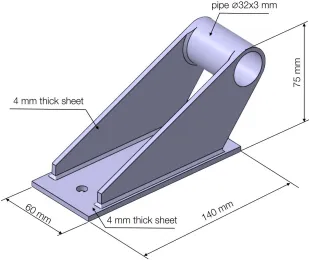
The object that will be optimized in terms of topology will be a typical technical holder. This holder was originally made of three sheet metal elements and a piece of pipe (Figure 1).
[image:3.612.140.449.237.499.2]All components of the holder are connected by welding technology. For further consideration, it was assumed that the holder was made of austenitic stainless steel 0H18N9 (by other markings X5CrNi18-10, DIN 1.4301, AISI 304). Its computational weight is 700.5 g.
Figure 1. Form and overall dimensions of the holder model.
SOFTWARE IMPLEMENTATION OF TOPOLOGICAL OPTIMIZATION
Figure 2. Boundary conditions and load of the holder model.
As an optimization criterion, weight minimization was assumed, while maintaining a safety factor of 1.5 and maintaining a minimum wall thickness of 4 mm. All computational and optimization activities are performed using the Altair Inspire 2018 system [1].
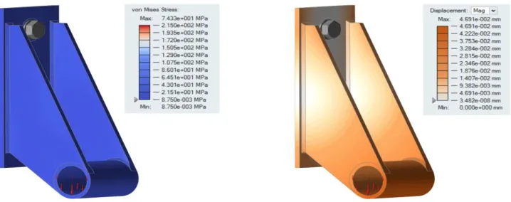
To maintain the correct reference point, the input model of the holder was subjected to a strength analysis (reduced stresses were taken into account, according to the von Mises hypothesis), according to these boundary conditions and the load. The results of this analysis (colour maps and scales of stress and displacements) are shown in Figure 3. As can be seen, the strength of the loaded holder is not large (the stress scale refers to the strength limit of the used material). This indicates, among other things, a large material allowance that causes an increase of mass and material use.
[image:4.612.118.477.515.657.2]Thus, the input model of the holder was subjected to topological optimization according to these guidelines. The result of this process is the theoretical form of the holder model (Figure 4).
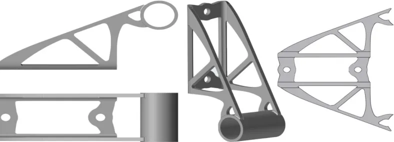
Figure 4. Theoretical form of the optimized holder model.
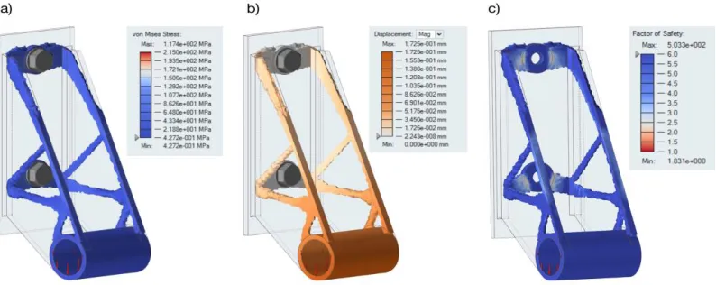
The obtained theoretical holder model was subjected to a strength analysis, according to identical boundary conditions and loads.
The results of this analysis (colour maps and scales of stresses, displacements and safety factor are visible in Figure 5, and the outline of the input holder model has been preserved in the background). We observe the increase in stresses and displacements, but the safety factor at a level of 1.8 has been preserved. However, there was a significant decrease in the mass of the holder. The computational mass is 211 g, which is a weight reduction of 30.12%.
[image:5.612.107.504.493.651.2]As already mentioned, the models obtained as a direct result of the optimization process are only theoretical (although nowadays technologically feasible, for example, with the use of print 3D technologies [5, 10]); therefore, further modelling activities should refer to obtaining a constructional form but including production technology.
The next chapter will describe two different design forms for the holder model.
CONSTRUCTION MODELS
The theoretical 3D model was used as the basis for the implementation of two models with designs adapted to make a real holder using two different technologies: conventional technology (sheet-metal working and welding) and generative technology—DMLS (Direct Metal Laser Sintering, i.e. selective sintering of metal powders) [10].
Sheet Metal Model
The sheet metal model (Figure 6) was made of the same material as the input model, i.e. steel 0H18N9. The construction of the holder has been divided into two parts: a bracket made of 4 mm sheet metal and a bushing made of a pipe Ø32x3 mm (the length of the pipe was slightly lengthened to obtain space for an additional fillet weld). The profile of the bracket has been applied to the sheet metal and then cut using cutting technology, e.g., water jet. Then, with the use of, e.g., press brakes, the bracket has been properly bent. The connection to the bushing was made using welding technology.
[image:6.612.108.502.515.657.2]The virtual model was made using the Generative Sheet Metal Design module of the CATIA v5 system. The holder model was made in accordance with the all principles of sheet bending (the bending radius was considered, and the layout of the model was verified on a flat sheet of metal).
3D Printed Model
During the modelling of the holder designed to be made using DMLS generative technology, small form changes were made. They concerned mainly the decommissioning sharp edges (characteristic of the sheet metal cutting process).
There is a slightly changed geometric form of the holder base, which does not need to be an integral part of the whole (as in the case of sheet metal cutting and bending). Between the base and the both side walls, rounding with larger radii have been added, which significantly reduced the stresses in these places (Figure 7).
3D print using DMLS technology must be done on a specific machine and using a specific material. Therefore, the EOSINT M270 printer was selected and the EOS StainlessSteel GP1 material [8]. EOS StainlessSteel GP1 material is supplied in the form of a steel powder. Its chemical composition corresponds to the standards of the USA 17-4 and 1.4542 X5CrNiCuNb16-4, and tensile strength (Rm) is 590 MPa.
This type of steel is characterized by good mechanical properties and especially excellent ductility, which is widely used in many different fields of technology.
[image:7.612.101.496.395.636.2]Importing the STL file theoretical holder model to the CATIA v5 system was done using the Digitized Shape Editor module. Other model activities were implemented using the Part Design module (the use of the solid modelling module was sufficient).
Comparison of Structural and Strength Characteristics of the Received Optimized Models
The strength properties of the models of the two holders are shown in Figures 8 and 9. As can be seen, the "printed" model is slightly more strenuous (increase in the maximum von Mises stress by 17 MPa and an increase in elastic deformation by 0.002 mm—Table 1). However, these values are so small that they can be omitted from the overall comparison. The more so that the assumed safety factor in both cases is greater than the assumed 1.5 (high maximum values apply to areas not optimized—Figures 8 and 9).
Both design models have a slightly higher mass compared to the theoretical model. This involves, among other things, the necessity of smoothing along the edge of the holder and the adaptation of the both models to the production technology. In the context of the sheet metal holder model, it comes with additional bending of the base bracket, elongation of the bushing and the addition of a weld. For the 3D printed handle model, the change of material is the most important change among others.
However, the weight difference between the two holder models is 20.77 g (weight reduction of 6.8 %), in favour of the 3D printed model. This is already a noticeable value, especially if the number of such holders mounted on the exemplary technical object was significant.
The geometric forms of both optimized holder models are very similar to each other. For the end user, this can be even unnoticeable. However, the technologies of their production are extremely different. The first used technology can be called traditional, but the second one (generative 3D printing) is already a quite modern technology.
The choice of one of the above proposed technologies should be dependent on factors other than the minimization of the weight criteria.
In the case of a mass production need of such holders, it will undoubtedly be cheaper to manufacture the holders made of sheet metal. In relation to the input holder model, there will be a significant reduction in weight (weight reduction of 57.10 %).
However, if the criterion of mass minimization (weight reduction of 60.04 %— Tab.1) is the most important for the constructor and the production is of unitary or low-serial character, the application of modern DMLS technology may be justified.
Of course, the used example of a holder as a technical object is quite simple as to the design, but also as to the manner of the load. In the case of multidirectional load (even static), the form of such a handle after topological optimization may take non-technological forms, taking into account conventional technologies. Then the only way out would be to use generative technology (3D printing).
reason for inhibiting the progress in the construction of many objects that have preserved conventional forms.
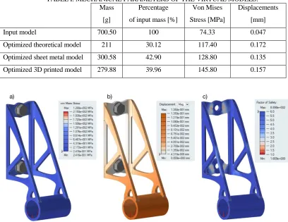
TABLE I. MECHANICAL PARAMETERS OF THE VIRTUAL MODELS. Mass
[g]
Percentage
of input mass[%]
Von Mises
Stress[MPa]
Displacements
[mm]
Input model 700.50 100 74.33 0.047
Optimized theoretical model 211 30.12 117.40 0.172
Optimized sheet metal model 300.58 42.90 128.80 0.135
[image:9.612.105.505.483.655.2]Optimized 3D printed model 279.88 39.96 145.80 0.157
Figure 8. Stress (a), displacements (b), and safety factor (c): Maps of the sheet-metal holder model.
SUMMARY AND CONCLUSIONS
Topological optimization should be already used at the beginning of the construction process as a method to assist the constructor in the selection of design features of technical objects.
The resulting theoretical virtual model as a result of topological optimization should be the input to the further construction process and should be treated as the boundary condition of the final design form. When selecting optimization criteria, the problem should be analysed very
carefully, especially in terms of boundary conditions and loads, because topological optimization leads to constructional forms tailored only to the adopted conditions.
The design criterion adopted for topological optimization may be different from the criterion (criteria) adopted in further proceedings, e.g., the implementation of the manufacturing process.
Generative manufacturing is generally suitable for the manufacture of any design form obtained as 3D model (virtual model), but the actual limitations may be the cost of production and the dimensions of the target object.
Confirmation of the theoretical results obtained from virtual models should take place with the use of experimental studies conducted on the handles produced using the two mentioned technologies.
REFERENCES
1. Altair: Solid thinking. 2019. Available from: http://www.solidthinking.com [Accessed 06 April 2019].
2. Bendsoe, M. P. 1995. Optimization of Structural Topology, Shape and Materia. Berlin: Springer-Verlag.
3. Bendsoe, M. P. and O. Sigmund. 2003. Topology optimization: Theory, methods and applications. Berlin: Springer-Verlag.
4. Chen, J. 2007. “Shape optimization with topological changes and parametric control”,
InternationalJournal for Numerical Methods in Engineering, 71(3):313–346.
5. Chlebus, E. 2003. Innowacyjne technologie rapid prototyping—rapid tooling w rozwoju produktu. Wrocław: Oficyna Wydawnicza Politechniki Wrocławskiej.
6. Dassault Systemes: CATIA v5. 2019. Available from: https://www.3ds.com/products-services/catia/products/v5/portfolio [Accessed 06 April 2019].
7. Dietrych, J. 1985. System i konstrukcja. Warszawa: WNT.
9. Patyk, R. and A. Kułakowska. 2012. “Topologiczna optymalizacja konstrukcji na przykładzie widłaka wału przegubowego”, Autobusy. Technika, eksploatacja, systemy transportowe, 13(5):380-386.
10. Siemiński, P. and G. Budzik. 2015. Techniki przyrostowe. Druk 3D. Drukarki 3D. Warszawa: Wyd. OWPW.