5237
IMPLEMENTATION OF SOFTWARE SYSTEMS PACKAGES
IN VISUAL INTERNAL STRUCTURES
AHMAD ABDULQADIR AlRABABAH
Faculty of Computing and Information Technology in Rabigh, King Abdulaziz University, Rabigh 21911, Kingdom of Saudi Arabia, e-mail: [email protected]
ABSTRACT
This manuscript discusses the visualization methods of software systems architecture with composition of reverse engineering tools and restoration of software systems architecture. The visualization methods and analysis of dependencies in software packages are written in Java. To use this performance graph it needs to describe the relationships between classes inside the analyzed packages and between classes of different packages. This article discusses system visualization with using matrices of incoming and outgoing packet dependencies, allowing analyzing existing dependencies between classes within a package, and between classes of different packages. Obtaining such Information allows us to understand the reason for the emergence of dependencies between packages that determine architecture of the system, and also if necessary refactoring systems. In the manuscript also described the possibility of tools to provide the infrastructure for subsequent detection and error correction design in software systems and its refactoring.
Keywords:Software Visualization, Reverse Engineering, Software Architecture, Dependency, Package.
1. INTRODUCTION
The task of reverse engineering in program system is very important in the development of a software system using libraries with source codes. Building and visualizing the UML model for the newly developed Program system [3], and for the libraries it uses, greatly simplifies the understanding of their structure and functionality [2,7], the choice of the required version and developer of the library. Ways Construction and visualization of the software system model were considered in previous works of the author [5]. This manuscript discusses the analysis and visualization of dependencies between classes in software systems packages written in Java language. This task is very important for restoration architecture of the software system when solving the problem of reverse engineering.
The size of information obtained in solving these problems can be too large for their perception by the user, reception and visualization of all relationships can require too much time [4,13]. Therefore, visualization of the software system is only necessary for the most significant part of its architecture. For the constructed UML-model it is necessary to calculate and visualize the values of object-oriented metrics allowing evaluating the
design of qualified systems [2,5,6]. In previous works, the methods of visualizing the system architecture and results of quality visualization were measured using Object- Oriented metrics [1,11]. Also an overview and analysis of oriented metrics was made, the simplest object-oriented metrics for analysis and design of individual classes, and then it was considered the class- structure metrics, allowing assessing the quality of the design in the class structure [9,14].
2. MATERIALS AND METHODS
2.1. Problem In Understanding Structure
Dependence Packages
5238 Errors in designing of system packages structure often affect the system as well. A recursive dependency of a package on other packages requires loading the code of these packets into memory devices with limited resources. To solve this problem it is necessary to apply package restructuring and to identify the package classes that have the maximum number of incoming and outgoing relationships to classes of other packages, also to determine the possibility of class moving to an external package that minimizes the dependency between packets.
Correspondingly important is the analysis of the relationships between the classes located inside the packages. Minimization dependencies between classes of large packages will allow you to restructure the package, breaking it into several smaller packages. Total number of dependencies between packages of the system in this case can be decreased [16]. To solve the problems of package restructuring as special visualization packages, allowing analyzing in detail the dependencies between packages and classes of packages. In previous works it was examined the analysis and visualization of dependencies of packets using matrices of the structure in the reverse engineering tool. This method of analyzing system packages allows simplifying the system structuring to levels and simplifying the extraction of the system architecture. To analyze and visualize the relationships between pair's packages of the system, a detailed visualization of the dependency matrix cells was used, showing relationships between a pair of packets represented by this cell. However, often the information in the matrix cells of structural dependencies is not enough. To remove the cyclic dependencies between packets and reducing the number of relationships between systems packages, matrices can be useful, showing the reasons for the dependency of the package with all other packages of the system.
To understand the interrelationships of packages, an essential visualization of packet metrics can help. Visualization of package nesting and the impact of such nesting on the software system architecture were discussed. Visualization and analysis of packet coupling, as well as joint the use of packets by classes was considered. Analysis of software system architecture with the help of matrices of structural dependencies is considered in the work.
2.2 Visualization For Understanding The Role Of The Package In The System
A.Choosing the way to visualize the package
Although the visualization of all the relationships of the package may need to show a very large amount related to the information package, however, it should simplify the analysis of the package. For visualization graphs, the most widespread are the visualization in the form of nodes and edges between nodes, and also visualization in the form of matrices. As was noted in [15], the representation in the form of knots and edges is easier to read and intuitively understood with a small number of nodes and edges in the graph. But the matrix representation has no problems associated with crossing the edges of the graph and superimposing nodes graph with a large number of connections between the bonds. Therefore, the matrix representation is more suitable for visualization of complex graphs.
B. Basic principles of package visualization
For the detailed package visualization regardless of the graph dependency complexity offered, use the matrix representation of the graph. The package is represented by a rectangle, whose sides form contact areas called surfaces. Each row / column represents the inner class of the analyzed package or the class of the external package with which interacts inner class of the analyzed package. The surface has a heading representing the relationship between the inner classes of the packet under consideration, and the body representing the interaction of internal classes for the analyzed package with external classes. To represent incoming and outgoing dependencies of the package are used separate types of packages.
5239
Figure 1. Visualization Of Package Dependencies As A Graph
A group of matrix rows related to a single packet form the surface of the bag. The first surface, related to the packet under consideration, is the package header. The E1 class refers to the inner classes C1 and D1. In classes B1, H1, I1, and F1, no classes of the P1 package refer, because there are no completed cells in the corresponding rows of these classes. The classes from the surface of the packet P3 is referenced from the packet P1 under consideration. These are classes A3, B3 and C3. The surface of the packet P3 is located in the matrix above the surfaces of the packages P2 and P4, since it includes more classes than the surfaces of packages P2 and P4.
To order the columns, surfaces and lines in surfaces, a single rule is used. Closer to the header are the surfaces packages that have the most links. Inside the surface closer to the header there are those classes on which the most links from the classes of the package considered. The background color brightness for the class name specified for the referring class shows how many links comes from the referring class in the cell of the column, in the package represented by the cell surface. Dark cell has more links. Both the horizontal position of the class and its brightness represent the number of Links. However, the position shows the number of references for the entire matrix, and the brightness for a particular surface of the matrix.
To separate the classes represented in the matrix into categories, the class color can be used. Matrix color might be used to separate the classes of the classes that have links and do not have a link. Non-referenced classes are painted in lighter colors, referencing in a darker color. In the matrix body, it is possible to allocate color packets and classes that are not included in the analyzed application. For example, in this way, classes can be painted in
packages from libraries received from external developers.
Consider now the package matrix showing the incoming dependencies of the package. For this purpose, a similar matrix with slight differences: the surfaces of the matrix of incoming dependencies are located horizontally. Thus, it will be easier to distinguish between matrices of incoming and outgoing dependencies, if they are located on the screen side by side.
3. EXPERIMINTS
3.1 Analysis of the packet structure with the matrix
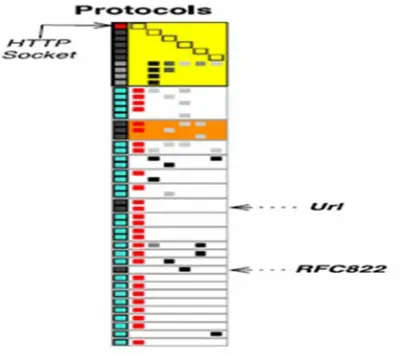
Now we illustrate the use of the matrix package to study the matrix structure and examine package dependencies. To analyze the packet structure of a matrix package, it is a necessitating for selecting/marking classes or packages (surfaces representing package). When we select a class, the class nodes and associated links are colored red. Also the most happens when the class is marked with the specified color at the request of the instrument user. Selecting/marking a surface means that all relationships are selected/ marked in the same way which enters the package represented by this surface. Figure 2 shows the matrix of output dependencies of the protocols package with the class which selected in the matrix.
Figure 2. Visualization Of The Selected Class HTTP Socket In Matrix Package Protocols
[image:3.612.317.517.461.638.2]5240 marking classes in the matrix of outgoing dependencies of the network kernel package is shown in the figure 3. Blue in Figure 3 is the socks socket class, green – class Internet configuration, and the crimson color - the class password. Also in Figures 2 and 3 were the surface of the packages is marked with an orange color as network kernel, and the surface of the protocols package is marked in yellow. Blue color is marked classes that do not belong to the application being analyzed (classes from external libraries).
Figure 3. Classes In The Matrix Of Output Dependencies Of The Network Kernel Package
Packet classes and surfaces are represented in the dependency matrices in a compact form. More Detailed about the class or package appears as a tooltip, as shown in Figure 4. The user tool can filter information with the displayed matrix of the packet. It is possible to display links referring only to the analyzed application, or to the described group packages. After excluding all classes of libraries used, the array of incoming dependencies of the package protocols takes a compact view, as shown in Figure 5.
Figure 4. A Pop-Up Tip For The Class HTTP Socket In Matrix Outgoing Dependencies Of The Packet Network
Kernel
Figure5. The Matrix Of Incoming Dependencies Of The Protocol Package After Filtering The Classes
The user can also use the filter to remove classes of unrelated relationships with external class packages or hide in the header of the matrix package, concentrating on analysis only dependencies between classes of different packages Figure 6.
[image:4.612.315.523.500.691.2]5241
3.2 Analysis Of The Package Using A Matrix Of Output Package Dependencies
Consider how the matrix of outgoing dependencies can be used for packet analysis. Such a quick look through the matrix on the "draft" package allows evaluating with the implementation of the package.
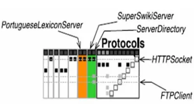
3.3 Analysis Of Large Packages
Consider packages that have a large size matrix of outgoing dependencies. The reasons for this may be different. Figure 6 shows three packets with a large packet matrix. The HTML parser entities package has a large number of its own classes, because it has a large Header. On the other hand, the remote directory and protocols packages have a large matrix, because contains a large number of references to classes in other packages (a large body) with a relatively small header of the matrix. A large number of matrix surfaces characterize closely coupled packages. Thus, the last two packages have a strong connection with their external environment.
3.4 Small Packages with Complex
Implementation
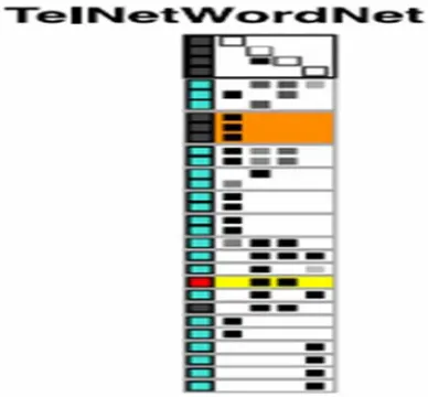
The TelNetWordNet class, shown in Figure 7, has
[image:5.612.91.285.450.630.2]only four classes of its own.
Figure 7. Telnetwordnet - A Small Package With A Complex Implementation
In addition, the package has a large matrix body and a large number of matrix surfaces. Based on this, we can conclude that loading this small package into memory will also require loading the large number code of their packages. This may lead
to problems on devices with a small memory. The remote directory class also has a small number of classes. However, its implementation is much more complicated Implementation of the TelNetWordNet class, since the dependencies of its classes are distributed among the larger number of outer classes and surfaces.
3.5 Sparse Packages
The package Html Parser Entities in Figure 6 and the package TelNetWordNet in Figure 7 have sparse Headers. This means that the coupling between classes inside these packages is small. It is possible that they are candidates for the decomposition of these packages (Distribution of package classes for other packages). At the same time, it can be noted that the package Html Parser Entities has not only a sparse title, but also a sparse body. For this reason its decomposition is more probable.
3.6 Packages With Internal Cohesion
The URL packet shown in Figure 8 has a large number of outgoing dependencies filled nodes. However, Figure 8 also shows that the URL package has many references to external packages in the body. Here, it's more important to link to classes of external packages than to classes inside packages.
Figure 8. URL - Package With Strong Internal Clutch
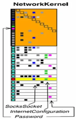
3.7 The choice of the position of the class
5242 So shown by the crimson rectangle in Figure 9, the password class does not have neither incoming nor outgoing dependencies within the header of the NetworkKernel matrix. Thus, the identified class becomes a candidate for moving it into packages; with classes which it has such dependencies. Moving a class to a using package will increase the cohesion of both packages.
Figure 9. An Incorrect Position Selection Of The Password Class In The Network Kernel Package
3.8 Analysis Of The Package Using The Matrix Of Incoming Dependencies
The incoming dependencies matrix shows how the package is used by other application packages. When analysis of packages is using such matrices, you can identify, for example, packet templates.
Leaf packages and insulated bags
Figure 10 shows the mail reader filters package list referenced by only one package mail reader. Also, using the matrix of incoming dependencies of the package, it is easy to identify in the system such fully isolated packages, as shown in Figure 10 of the Squeak Page package.
Figure10. Leaf Packages And Fully Insulated Packages
4. RESULTS AND DISCUSSIONS
To illustrate coupled Packages, consider the matrix of incoming dependencies of the kernel package, shown in Figure 11. The classes that have the most links are classes that are in the body packets with large surfaces, like socket and net name resolver located in the top two rows of the matrix. However, the string for the net name resolver class is darker than the string of the socket class. This means that the net name resolver class has more internal incoming dependencies than the socket class. And the socket class has more incoming external dependencies, since the brightness is represented by the number of references to the package classes in the body of the packet.
Figure 11. Intensively Used Package Classes
4.1 Related Packages
To assess the impact of a change in one package on another package, it is often necessary to identify system closely related packages. A sign of the close cohesion of packets is a large surface package in the body of the packet required, close to the header of the packet. Example, closely related packets are shown in Figure 10 with the matrix of incoming dependencies for the package mail reader filter. Closely related package, in accordance with the above criteria is a mail reader package. Another example of close bundling of packets is shown in the figure 11. The Protocols package is closely related to the Kernel package. Changes in the Kernel package will significantly affect to classes in the protocols package.
4.2 Kernel Packages
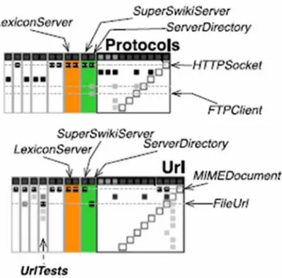
[image:6.612.314.520.301.408.2]5243 the matrix of incoming dependencies for these packages.
Figure 12. Packages URL And Protocols From The System Kernel
5. CONCLUSION
The manuscript considers methods for visualizing dependencies using a matrix representation of a graph describing the relationships between the classes within the parsed package, and the relationships between the classes of the different packages. Showing use this method to visualize the dependencies between packages in the inverse tool design and restoration of architecture. This tool is based on the UML modeling language and it is implemented as an extension of the eclipse environment and the manuscript is considered effectively as an implementation of the life cycle phases in software engineering and application of the modeling language UML.
ACKNOWLEDGEMENT
I thank King Abdulaziz University- KSA for providing me with needed resources for carrying out this work.
REFERENCES:
[1] Addy Osmani, Learning JavaScript Design Patterns: A JavaScript and jQuery Developer's Guide, O'Reilly Media, 2012.
[2] Colin Ware, Information Visualization, Third Edition: Perception for Design (Interactive Technologies) 3rd Edition, Morgan Kaufmann, 2012.
[3] S. Ducasse, M. Lanza, L. Ponisio, Butterflies: A visual approach to Characterize packages, in: Proceedings of the 11th IEEE International Software Metrics Symposium (METRICS'05), IEEE Computer Society, 2005, pp. 70-77. [4] Stephanie D. H. Evergreen, Effective Data
Visualization: The Right Chart for the Right Data 1st Edition, SAGE Publications, Inc. 2016. [5] Saikat Das Gupta , Rabindra Mukhopadhyay ,
Krishna C. Baranwal , Anil K. Bhowmick, Reverse Engineering of Rubber Products: Concepts, Tools, and Techniques, CRC Press,2013.
[6] Bruce Dang , Alexandre Gazet , Elias Bachaalany , Sebastien Josse, Practical Reverse Engineering: x86, x64, ARM, Windows Kernel, Reversing Tools, and Obfuscation 1st Edition. Wiley, 2014.
[7] Dhanji R. Prasanna, Dependency Injection: With Examples in Java, Ruby, and C#, Manning Publications, 2009.
[8] M. Lungu, M. Lanza, T. Girba, Package patterns for visual architecture recovery, in: Proceedings Of CSMR2006 (10th European Conference on Software Maintenance and Reengineering), IEEE Computer Society Press, Los Alamitos, CA, 2006, pp. 185-196.
[9] Vinesh Raja and Kiran J. Fernandes, Reverse Engineering: An Industrial Perspective (Springer Series in Advanced Manufacturing), Springer; Softcover reprint of hardcover, 2010. [10] Kyran Dale, Data Visualization with Python
and JavaScript: Scrape, Clean, Explore & Transform Your Data 1st Edition, O'Reilly Media, 2016.
[11] H. Abdeen, I. Alloui, S. Ducasse, D. Pollet, M. Suen, Package reference fingerprint: a rich and Compact visualization to understand package relationships, in: Europe an Conference on Software Maintenance and Reengineering (CSMR), IEEE Computer Society Press, 2008, pp.213-222.
[12] N. Sangal, E. Jordan, V. Sinha, D. Jackson, Using dependent models to Manage complex software architecture, in: Proceedings of OOPSLA'05, 2005, pp. 67-176.
5244 [14] M. Ghoniem, J. D. Fekete, P. Castagliola, A
comparison of the read ability of graphs using Node-link and matrix-based representations, in: Proceedings of the IEEE Symposium InformationVisualization, INFOVIS'04, IEEE Computer Society, Washington, DC, USA, 2004, Pp.17-24.
[15] A. A. AlRababah, Lempel - Ziv Implementation for a Compression System Model with Sliding Window Buffer", International Journal of Advanced Computer Science and Applications (IJACSA), Volume 6, Issue10, 2015.