189
A TREEMAP BASED NETWORK VISUALIZATION SCHEME
FOR DETECTING NETWORK ATTACKS
1 WALID I. KHEDR, 2ABDEL-GHAFAR EMARA, 3IBRAHIM ZIEDAN
1 Associate Professor, Faculty of Computers and Informatics - Zagazig University, Department of IT, Egypt 2 Faculty of Engineering - Zagazig University, Department of Computers and Systems, Egypt 3 Professor, Faculty of Engineering - Zagazig University, Department of Computers and Systems, Egypt
E-mail: 1[email protected], 2[email protected], 3[email protected]
ABSTRACT
Because of the rapid increase in the size and complexity of computer networks and the growing increase in the number of users, network security administrators are being overloaded with large volumes of data (logs from various sources and many security events to monitor). Due to its nature, these data are impossible to handle manually, and even most automated data analysis tools are inadequate. One of the main effective solutions for securing complex computer networks is visualization. Visualization transforms data into visual objects which help administrators to achieve real-time supervision, fast reaction and real-time detection of emerging attacks. In this paper, a novel treemaps based network visualization scheme is proposed. The proposed scheme groups many network traffic attributes (source IP, destination IP, port number and packet size) in a simple and manageable interface. The proposed scheme also combines traffic from the same country in single Treemap rectangular region. Usability analyses show that the proposed scheme is efficient and has a high level of usability.
Keywords:Network Security, Data Visualization Techniques, Treemap, Geolocation Database
1. INTRODUCTION
Inspecting network traffic is an essential method to see traces left by an attacker. Log files are generated in response to both malicious and innocuous activities. These logs and traces are what network security professionals must work with to detect and prevent network attacks. The problem is the vast amount of network traffic data to be processed. The aim of any security tool is to find patterns, determine if these patterns are anomalies and communicate the severity of the attack. One of the most useful tool for network security administrators is visualization.
A novel system that aimed to transform a large amount of information about network traffic into a simple and clear visual form is proposed. To achieve this, we identified the drawbacks of previous related work and proposed an enhanced scheme that overcomes those drawbacks and combines their advantages. The proposed system represents many network attributes (e.g. port number, source IP, destination IP...etc.) in a two-dimension view.
Since the observed network attributes are related to each other by hierarchical relationships, these
attributes are displayed in a hierarchical map. A common way of displaying hierarchical data is with layouts where child nodes are placed under their parents. The most important layouts of this type are treemaps[6]. The proposed hierarchical layout is based on the following network attributes:
Source IP address: which is also resolved to its country using the geolocation database[1]. Destination IP address: refers to an internal host
IP on the victim network.
Destination port number: The victim’s internal host port which the attacker tries to access. Packet size: refers to the size of the packet that
the source IP sends to destination IP.
1.1 Contributions
190 Our proposed scheme display many network
traffic attributes (source IP, destination IP, port number and packet size) in a simple and manageable interface based on Squarified Treemaps algorithm [11].
Our proposed scheme grouped the destination ports based on its usage. Numerical division, which is used by other related work[13] is divided the ports according to its numerical value without regardless of their usage (e.g. many important ports are under the first one hundred ports are placed into a single bin in Abdullah et al.[13]), this is one of the drawbacks.
Destination ports are encoded using CMC color differencing algorithm [16, 17] which produces distinct color within a certain tolerance. Representing the source (attacker) IP address
using both the source country and IP address. Our proposed scheme shows both port activities
and internal/external hosts representation in the same graph. This allows our visualization system to detect a wide variety of interesting security events.
The proposed scheme has a manageable interface that can be used for Host/Server monitoring. So, it can cover many class of network visualization that are classified in previous work[9].
The proposed scheme makes use of Akamai Content Delivery Network (CDN) [2] to represent countries that are classified as the main platform for attacks in the world. To the best of our knowledge, no previous studies made use of such international attack reports.
The rest of this paper is organized as follows. Section 2 introduces related work. Section 3 reviews relevant background. Section 4 describes the phases, layout, and structure of the proposed system. The security analysis, performance evaluation of the proposed scheme and case study are presented in section 5. The usability evaluation of the proposed scheme is presented in Section 6. Finally, Section 7 concludes the paper and suggests future work directions.
2. RELATED WORK
To refinement of visualizing and analyzing network traffic, many previous studies have been proposed in diverse aspects:
Portall[15] is one of the unique systems that visualization connection between hosts and servers in the same network. It tried to dig into the nature of
the connection, and at the same time represents it by simple way. In Portall[15] the servers are on the right side vs. the hosts in the left one. The line that connected between host and server represent the type of connection between them. Portall[15] correlates network traffic to host processes, this feature allowing spyware and ad-wares to be easily detected [15], but with a huge amount of connection, the observer can’t determine the source and destination. So, this system is suitable for a small network.
VISUAL[5] is classified as internal/external monitoring system [9]. It allows the observer to see communication patterns between internal networks and external sources in details. It represents all internal hosts as cells in a square grid in the middle of the screen, with white space around it. In the empty area around the internal hosts, the external hosts are represented as squares. The amount of host IP activity is represented by the square size of external hosts. Lines in the square are used to denote port traffic. Grid color denotes communication between computers internally whereas line connections between internal and external hosts denote traffic flow. The VISUAL system ignores the connection details and with large number of connections the displayed layout becomes very complex.
191 Figure 1:Color scheme at visualizing network data for
intrusion detection[13]
3. PRELIMINARIES
In this section, we give an overview of the international reports of highest countries in the export of threats and attack traffic. This section also
gives an overview of the geolocation database which is used to identify the attack traffic originating country.
3.1 Attack traffic origin reports
In the proposed scheme the country name used to represent the source IP address, which was one of the missing features of other systems[9]. Table 1 shows the list of top originating countries which is responsible for top attack traffic. Based on our study of Akamai CDN [2] which are summarized in Table 1, we notice that some countries are always in the list of the top ten countries that represent the top attack traffic in the world[2]. This statistic helps the observer to determine the countries' traffic that must review minutely.
3.2 Geolocation Database Service
To resolve real IP to its country name geolocation databases is required. Many
IP-geolocation databases are available e.g. IP2Location, MaxMind, GeoBytes, IPligence, and Spotter [1]. The MaxMind database is selected as the most accurate Table 1: Top originating countries that represent the top attack traffic from 1st quarter in 2013 to 1st quarter in 2017[2].
No Country
Q
1/
13
Q
2/
13
Q
3/
13
Q
4/
13
Q
1/
14
Q
2/
14
Q
3/
14
Q
4/
14
Q
1/
15
Q
2/
15
Q
3/
15
Q
4/
15
Q
1/
16
Q
2/
16
Q
3/
16
Q
4/
16
Q
1/
17 Frequency capping**
1 Brazil* 8 8 6 8 5 7 7 8 3 3 3 2 2 1 4 4 3 17
2 China 1 2 1 1 1 1 1 1 2 1 2 6 4 5 6 6 4 17
3 Russia 5 7 5 7 6 6 5 4 8 5 4 3 6 4 3 5 8 17
4 USA 3 3 3 2 2 3 2 2 1 2 1 1 1 2 1 1 1 17
5 India 6 6 - - 7 5 4 7 4 - - - 10 9 - 10 - 10
6 Germany - - 7 10 - - - 9 - 4 - 8 8 3 5 3 5 10
7 Taiwan 7 4 4 5 4 4 3 3 - 6 - - - 9
8 Indonesia 2 1 2 4 3 2 6 - 9 9 - - - 9
9 Netherlands - - 6 - - - 7 8 4 3 6 2 2 2 9 10 Romania 9 9 8 9 10 10 - - - 5 - - - - 7
11 Turkey 4 5 - - 8 9 9 5 - - 9 - - - 7
12 South Korea 10 9 - 9 8 8 6 - - - 6
13 France - - - 7 - - 5 - 7 8 9 6 6 14 UK - - - 5 - 7 - 7 - - 7 7 5 15 Canada - - - 3 - - - - 6 - - 9 - 10 - - - 4
16 Ukraine - - - 8 6 - 9 - - - 9 4 17 Lithuania - - - 9 8 10 3 18 Hong Kong 10 - - - 10 - - - 2
19 Singapore - - - 10 - 8 - - - 2
20 Bulgaria - - - 5 - - - 7 - - 2
21 R.of Moldova - - - 10 - - - 1 2 22 Italy - - - 10 - - - 1
23 Venezuela - - 10 - - - 1
24 Japan - - - 7 - - - 1
25 Ireland - - - 10 - - - 1
26 Spain - - - 10 - - 1
27 Venezuela - - - 10 - - - 1
* Rank of each country in the report of the quarterly report.
[image:3.612.75.547.308.637.2]192 database among other IP-geolocation databases. The choice of MaxMind database is based on a comparison between geolocation service provider databases published in [1]. This comparison is shown in Table 2 and Table 3.
Table 2: Geolocation database accuracy [1]
Database Country Level City Level USA City Level
IP2Location 99% 80% -
MaxMind 99.8% Varies 83%
GeoBytes 97% 85% -
NetAcuity 99.9% 95% -
Akamai - 97.22% 100%
Quova 99.9% - 97.2%
According to Table 2, the best vendors that have satisfied the best accuracy over the country are Quova, NetAcuity, and MaxMind. Over the city level, the accuracy varies from vendor to the other. The city level is not considered; since we work at the country level.
A comparison between geolocation database results is another factor that can be used to determine the best vendor that has the highest match with other providers, as shown in Table 3.
In Table 3, the left column and the upper row contain the same geolocation database name; each cell contains the percentage of the result identical rate between the databases in the left column and the upper row.
According to the previous comparisons of the different geolocation vendors, it seems that the accuracy changes from provider to another. MaxMind lite had the greatest overall agreement with most of the databases with approximately 95.4%. This is the best value that had been achieved. At the same time, the accuracy factor of the MaxMind database achieved accuracy by 99.8% at the country level. This reduces the probability of error. All previous reasons lead us to use the MaxMind Lite database.
4. PROPOSED SYSTEM DESIGN
The proposed system provides a set of interactive features that enables network administrators to
discover anomalous traffic patterns. Building such a system requires a precise construction of every part of it. Captured traffic goes through many phases to obtain final view layout.
Table 3: Comparison between geolocation database results[1]
RIR Soft HostIP Iplig Cys MaxG MAxL DigE Avg1
RIRf 99.9 88.9 89.3 93.6 94.1 94.2 91.8 93.8
Software77fv 99.4 88.8 88.6 93 93.5 93.6 91.2 91.6
HostIPf 14.1 14.2 13.9 15.4 14.4 14.4 14.9 14.6
IPligence v 85.4 85.3 83.8 89.3 89.5 89.6 86.2 87.6
Cyscape v 90.7 90.6 94.2 90.4 93.2 93.3 95.7 92.5
MaxMind GeoIP v 94.1 94 90.9 93.5 96.2 99.8 94.9 94.7
MaxMind GeoLitef 94.2 94.1 91 93.6 96.3 99.8 94.9 95.8
Digital Envoy v 91.8 91.7 93.9 90 98.8 94.9 94.9 93.9
Average1 92.3 90.4 90.3 90.6 94.3 92.8 94.3 92
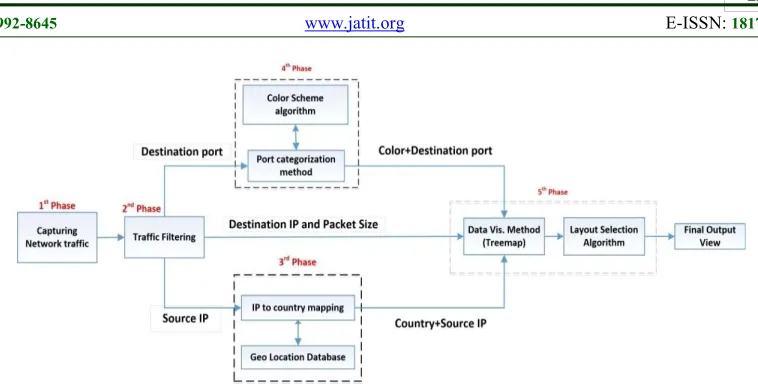
[image:4.612.125.491.364.468.2]193 As shown in the above figure, capturing traffic is the first phase in our system. The WinPcap[19] tool is used to capture live network traffic. After capturing the required traffic, the traffic is filtered to extract the required attributes (Source IP, Destination IP, Destination port and Packet size), which is done in the second phase. During the third phase, the source IP is resolved to its country name using the geolocation database. In phase four, port numbers are categorized as discussed in Section 4.4. The categorized ports are colored according to CMC (I: c) color differencing algorithm[20, 21]. In the final phase, the outputs of previous phases are arranged into a Treemaps view using Squarified Treemaps layout algorithm[11] to generate the final view. All these phases are explained in more details in the following sections.
4.1 Data capturing phase
In this phase, records that represent aggregate traffic are captured using WinPcap[19]. In a case study that explained in Section 5.1, network traffic is captured before being processed by any security device as the security appliances filtered malicious traffic and processed it. Obtaining full traffic without processing helps administrators to detected threats, which may undetectable by the security appliances, this gives the administrator the ability to evaluate the correctness of security devices used to protect the network.
4.2 Traffic filtering phase
During this phase the source IP, destination IP, destination port and packet size are extracted from the header of each packet. Packet payload is ignored which helps to reduce the computation cost of the next phases.
4.3 Source IP resolving phase
In this phase, the source IP address is resolved to its country using the MaxMind Lite geolocation database[22]. Resolving source IP address to its country helps to represent the vast number of real IPs in a simple view. The observer can use countries name to group each country's traffic together, which helps in reviewing the country traffic according to hacking reports that determine the top originating countries which is responsible for top attack traffic [2].
4.4 Port categorization and coloring phase 4.4.1 Port categorization method
Monitoring the entire range of ports is an expensive and a hard task. Also, according to critical security controls rules which was published by SANS Institute [18], predefined ports are opened for external users to access internal network resources depending on the provided services, all other unused ports must be closed. So, we focused our efforts on observing open ports individually while observing closed ports in groups.
[image:5.612.121.500.67.260.2]Previous systems, which monitor ports activity, grouped ports without analyzing or reviewing its importance. To improve ports grouping, in our proposed scheme the network administrator predefines open ports and assigns one color to each one. The range of unused port, which could be located between two used ports, is represented as one group visualized by one color, as it is clear in Table 7. Thus in this distribution, we have been able to observe the 65535 ports effectively and improve the division method of previous work[13].
194 4.4.2 Color scheme
The CMC (I: c) color differencing algorithm[20, 21] is used for port coloring. It is used to generate a set of visually distinct colors within a certain tolerance. Color selection is influenced by several values; these values are explained in Figure 3 (e.g. L (Lightness), C (Chroma) and H (Hue angle)).
Figure 3: Lab color space pictures
The equation that calculates ∆ECMC ( that represent
the distance of a color (L*2 , C*2, h*2) to a reference
color (L*1 , C*1, h*1)) [16, 17] is:
2 2
2 *
* * * *
* 2 1 2 1 ab
CMC
L C H
H L L C C
E
lS cS S
Where:
• ∆L*, ∆C*, ∆H*: differences of two color
parameters being compared,
• l and c : brightness and saturation respectively, • SL, SC, SH : additional functions described by the formulas:
* 1 *
* 1
1 * 1
0.511 16
0.040975
16 1 0.01765
L
L
s L
L L
* 1 * 1 0.0638
0.638 1 0.0131
C
C S
C
And
(FT 1
)
H C
S
S
F
*4 1 *4
1
1900
C
F
C
1 1
1
0.56 0.2cos(h 168 ) 164 345
0.36 0.4cos(h 35 )
h T
otherWise
o o o
195 This produces a set of visual distinct colors within a certain tolerance based on CMC (I: c) color differencing algorithm[20, 21], which is an enhancement over other previous color map methods that are based on randomly chosen colors[9].
4.5 Visual layout creation phase
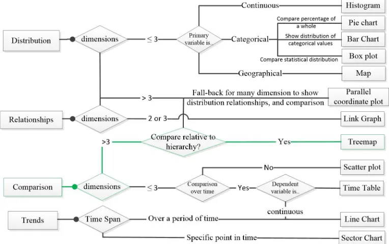
We adopt the Treemap approach to visualize network traffic as it has three unique properties that turn out to be advantaged over other types of graphs. The first advantage is that Treemaps can show relationships based on hierarchies; it is easy to compare different data dimensions with each other. Secondly, Treemaps are great at visualizing more than just three-dimension data. The third advantage is that clusters are easily detectable[6].
Raffael Marty[6] introduced a flow chart, Figure 4, that simplifies the operation of choosing the right chart for data based on use-case. The proposed scheme is based on comparison between the traffic patterns, so we start from the comparison use-case. The next step in flowchart is based on the number of
dimensions. The proposed system has four attributes. Since the number of attributes is greater than three, the “compare to hierarchy” path is chosen. Hence, the Treemaps is the best chart for the proposed system. The green path in Figure 4 shows the selected chart for the proposed system.
4.5.1 Layout algorithm selection
Optimal usage of the screen area helps the administrator to display a huge volume of data without losing details, so we used Squarified algorithm [11]. The Squarified algorithm tries to obtain the best aspect ratio for each node. It present nodes as more square-like rectangles with similar aspect ratio; comparison of the size of rectangles is easier when their aspect ratios are similar. This helps the observer to detect the attacker who consumes the bandwidth of the network. Also, Squarified algorithm organized nodes by way to makes it easy to extract information just by looking.
[image:7.612.97.479.171.411.2]So Squarified algorithm achieves the best view with the best arrangement of nodes to show all available data in the view, and this is what we aim to achieve.
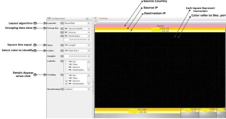
196 4.5.2 Proposed system layout
In the proposed scheme, after the captured traffic passes through all phases, the captured traffic is visualized in the final view as shown in Figure 5. On the left of the view, the observer can see the control panel of the system, where he can arrange the priority of the attribute in the arrangement. The right side of the view contains a group of overlapping squares depending on each other in a hierarchy relation. The default arrangement of the attributes in the right side; the main square is the country square containing traffic comes from certain country. Each source IP comes from this country is represented by a square
in a country square. Each source IP square contains smaller squares represent the destination IPs that is targeted by that source IP. Destination IP square contains smaller square, each one of them represents
a packet of a connection. The color of this packet square, according to default arrangement, refers to the destination port. The size of all squares in all levels is proportional to the size of traffic. Finally, the observer obtains the following view on its screen as shown in Figure 5.
The observer can change the priority of arrangement according to (Source GeoIP Country, Source IP, destination IP, destination port, or traffic length). So, he can see the data flowing at more than one perspective. This feature is not available in previous systems. The proposed system also displays the connection details when the observer hovers over
any area in the view. The observer can zoom in any specific region, country, or IP region by clicking on it, so the system rebuilds the view to display the required area in the whole view.
The proposed system achieved the follow feature: F1. Two-dimensional layout: It is better to
use two-dimensional layout for displaying network traffic data to make the layout easier to understand and interpret. This is difficult to achieve when the three-dimensional layout is used.
F2. Representation of destination ports: Ports are represented as by the color of the rectangles.
F3. Representation of source IP address: Source IP addresses are represented as rectangles.
F4. Representation of destination IP address.
F5. Representation of packet size: it is represented in the main view by the size of square.
F6. Dynamic layout: The new system has great flexibility as the observer can rearrange the dimensions that are represented (port number, source IP, destination IP, etc.) according to his requirement.
F7. High and low-level analysis: the administrator will be able to drill-down into the abnormal areas of the network to know what happens in detail and how to combat this.
[image:8.612.117.492.260.458.2]197 full details gives us the chance to display a huge volume of data without losing details.
F9. IP-to-country resolving: External IP address resolved to its country according to the geolocation database.
F10. Simple user interface: With this vast number of attributes and data the system is simple and easy to use. Based on these features, a comparison between the proposed system and previous systems feature is presented in Table 4:
5. SYSTEM EVALUATION
5.1 Case Study
To demonstrate the fitness of our proposal, we conducted case study with data from our university network.
WinPcap[19] was used to obtain records that represent aggregate traffic in the network; we filtered unwanted traffic (e.g. traffic that target local users), this allowed us to focus on more critical traffic that targets the DMZ (Demilitarized Zone) that contains the main servers of our university.
The implementation of the proposed scheme is implemented using Java, Swing GUI widget toolkit and Macrofocus Treemap API [23]. Swing GUI widget toolkit is used to design the main UI of the proposed scheme. The UI gives the observer the ability to arrange the Treemap view depending on multi-attributes like source IP address then Destination address. The default arrangement of output view of all test scenarios is source GeoIP, source IP, and destination IP. The colors discriminate destination ports and the square size is used to refer to the packet size.
5.1.1 Port categorization evaluation
To group ports according to the proposed scheme, as described in section 4.4.1, we determined all open ports for external users to access the local network of
the university; all other ports are closed. These ports are summarized in Table 5. This list of ports matches the statistics mentioned in [24]. Closed ports won’t be neglected, but it will be monitored in groups to save observer efforts and to make the final view simpler.
In our grouping techniques, we first divided the port range into three main parts according to IANA division: well-known ports, registered ports, and dynamic ports. Then, each section is divided into subdivisions as shown in Table 6.
The well-known port (0 to 1023) includes most of our case study's open ports; each open port is represented individually e.g. Port 21 and port 25. The range of unused port, which is located between two used ports, is represented as one group, visualized by one color e.g. Port range 22-24 that located between Port 21 and port 25.
Registered ports are the second part of our division that covers ports from 1024 to 49151. In this range Table 4 Feature comparison between proposed system and previous system
Pr op os ed Sy st em N V is io nI P [3 ] N et B yt es [4 ] V is ua l[ 5] N Fl ow V is [ 7] Y el iz ar ov a nd G am ay un ov [8 ] SV is io n[ 10 ] T he S pi nn in g C ub e of Po te nt ia l D oo m [1 2] A bd ul la h et al .[ 13 ] H os t N et w or k (H oN e) [1 4] Po rt al l[ 15 ] System/ Feature √ √ x √ √ x x x √ √ √ F1 √ √ √ x x √ √ √ √ √ √ F2 √ √ x x √ x x √ x √ √ F3 √ √ x x √ x x √ x √ √ F4 √ x √ √ x √ x x √ x √ F5 √ x x x √ x x x x √ x F6 √ √ √ √ √ √ x x √ √ √ F7 √ x x x x x x x x x x F8 √ x x x x x x x x x x F9 √ √ x √ x x x x √ √ √ F10
198 of ports, only one port is open in our university network for external hosts, which is port 3389. This port is used for the remote desktop protocol. Since it is the only open port in the range from 1024 to 49151, we grouped all range in five groups, the first group cover from 1024 to 9999, the second covers from10000-19999, the third covers from 20000-29999, the fourth 30000-39999, and the last group 40000-49151. The division of registered ports to five groups helps in detecting the port scan in it, if registered ports are one group, we will lose this feature.
The third part of the division is the Dynamic ports that start from 49152 to 65535, and this part is rare to use. So, we grouped it in one group to save observer effort and focus.
Table7 The Suggested port division techniques.
Well-known ports area Port Range Port Range
143 0-20
144-442 21
443 22-24
444-464 25
465 26-52
466-586 53
587 54-79
588-992 80
993 81-109
994-995 110
996-1023 111-142
Dynamic ports Registered ports
49152 -65535 1024-9999
10000-19999 20000-29999 30000-39999
In this way, we have been able to observe all of the 65535 ports effectively and improved the port division method of previous work[13].
5.1.2 Color scheme
[image:10.612.331.517.82.348.2]The CMC model [16, 21] is used to obtain twenty-eight distinct colors that cover all required ports that are discussed in section 5.1.1 as shown in Table 7:
Table 8 Distribution of colors on ports
No Port Range Color Color Code
1 0-20 #400606
2 21 #ff4040
3 22-24 #bf697f
4 25 #7f290d
5 26-52 #ffa98c
6 53 #ff9f40
7 54-79 #7f5933
8 80 #ffffff
9 81-109 #ffd966
10 110 #344010
11 111-142 #b1bf86
12 143 #80766c
13 144-442 #19ff1a
14 443 #30bf54
15 444-464 #468063
16 465 #6c807b
17 466-586 #463380
18 587 #1ac6ff
19 588-992 #336c80
20 993 #697fbf
21 994-995 #4040ff
22 996-1023 #30bfbf
23 1024-9999 #312340
24 10000-19999 #ecd9ff
25 20000-29999 #bf13bf
26 30000-39999 #ffb3ff
27 40000-49151 #ff1a8c
28
49152-65535 #000000
This is an advantage over previous systems which use random colors to create the color map [13].
5.2 Attack evaluation
The following attacks are the most common type of attacks that target computer networks. Table 9 summarized the attack tools description, which we used in our experiment.
5.2.1 Network Scanning and Mapping
Scanning a network is commonly a precursor to any attack[25, 26]. A blueprint of the network can be made to find active ports and IP addresses on the victim network. This can be achieved by sending probe packets to the victim network.
[image:10.612.106.284.289.515.2] [image:10.612.103.277.624.729.2]199 The Angry IP scanner[27]: is an IP scanning tool. Its output is shown in Figure 6. As shown in the figure, a single source IP is represented by one big square with a dark yellow tape over it, containing the IP address. This square contains many squares inside it. Each internal square has a yellow tape over it containing destination IP. In each destination IP square, we can notice that there is at most two colors; this means that this tool particularly focused on IP scan only.
Figure 6: Angry IP scanner [25]
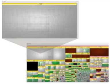
[image:11.612.314.527.287.464.2]Advanced port scanning tool[28]: is another tool which is different from the previous tool (Angry IP scanner); this tool targets all destination ports in each destination IP. The observer can see one square that represents the source IP which contains multi small square that represent destinations IPs like the output of previous tool. However, the observer will notice that this tool targets more destinations port in each destination IP, as shown in Figure 7.
Figure 7: Advanced Port Scanning tool [28]
As noticed in the previous figures, the proposed scheme can detect the scan process and give the observer a distinctive image in a full screen view. The proposed system detects the scanning process targeting the network. Port scan is represented by variation in colors which make it easy to be detected, even if the amount of traffic is small (small squares). Targeting different destination can be distinguished by the repeated rectangles pattern under each one source IP.
5.2.2 Denial of service
Denial of service is a well-known attack [29, 30]. It aims to make the service unavailable to its intended clients by sending a huge amount of traffic to it. Abnormal high volumes of traffic can easily be detected visually by the observer using the proposed system. The observer can drill into the details of information to determine the running services and explore exactly how to protect it from that attack. The traffic size is represented by the size of its rectangle, as shown in Figure 8.
Table 9 Attack tools description
Attack Tool Description
Network Scanning and Mapping
Angry IP scanner An open-source and cross-platform network scanner tool designed to be fast and simple to scan network.
Advance Port Scanning
A free network scanner tool allowing it's user to quickly find open ports on network computers and retrieve versions of programs running on the detected
ports.
Denial of service DosHTTP A powerful HTTP Flood Denial of Service (DoS). DoSHTTP is easy to use.
SQL Injection Acunetix web vulnerability Acunetix used for SQL Injection, XSS, XXE, SSRF, Host Header Injection and over 3000 other web vulnerabilities.
Mail Attack Bomb Mail
A mail bomb tool is sending a massive amount of e-mail to a specific person or system. A huge amount of mail may simply fill up the recipient's disk space on the server or, in some cases, may be too much for a server to handle and may
cause the server to stop functioning.
Password attack DUBrute
[image:11.612.92.296.411.582.2]200 The observer will notice that one source IP targets only one destination IP in the internal network by a huge amount of traffic that is represented by a huge square where the size of square refers to amount of traffic. The dark yellow tape over the square contains the source IP address and the single yellow tape refers to a single destination IP and the single color refers to a single port.
Figure 8: Denial of service attack
Figure 8 contains another huge black square with two tapes: a dark yellow which refers to one source IP and a yellow tape which refer to a single destination IP. The square’s black color shows that the attacker targets dynamic ports, according to color map in section 5.1.2. This square refers to a denial of service that target IP address x.x.29.16 in the internal network.
5.2.3 SQL Injection
Acunetix web vulnerability is a well-known SQL injection attack tool [31, 32]. As shown in Figure 9, SQL injection attack output is similar to that of the denial of service attack. However, SQL injection targets the HTTP port.
5.2.4 Mail Attack
Mail system represents an essential part of any enterprise network, so we launched a demo bomb mail attack [25].
Figure 10: Bomb mail attack
Figure 10 shows the output of proposed system. The bomb mail attack is represented by a big square colored by the color of SMTP protocol port, according to color map in section 5.1.2. The dark red square in the upper left refers to the huge amount of traffic target SMTP port which is used by mail service. This huge amount of traffic comes from one source; this behavior refers to bomb mail.
5.2.5 Password attack
[image:12.612.99.300.191.357.2]Password guessing attack (PGA)[25] is a method of breaking into a password-protected computer or server in the network by systematically entering every word in a prepared dictionary as a password. Most networks aren't configured to require long and complex passwords, and an attacker needs to find only one weak password to gain access to a network.
Figure 11: Password guessing attack (PGA)[25]
[image:12.612.315.520.503.677.2] [image:12.612.98.289.571.718.2]201 data (passwords) for each one. This amount of data targets Remote desktop protocol (RDP), according to color map in section 5.1.2. The attacker tries to guess the password for the servers, which RDP open on it for external hosts.
5.2.6 Observed real time attacks
[image:13.612.314.524.133.314.2]We use our proposed system to observe the traffic in the university network. The proposed system detects the follow attacks that displayed in the follow figure.
Figure 12: Real threads from China
The previous figure represents the traffic that arrives from China that is classified as the main platform for an attack in the world [2] to the victim network. The proposed system observes two real IPs
scanning the range of an internal network. They don't
scan ports but scan a range of IPs using the specific port.
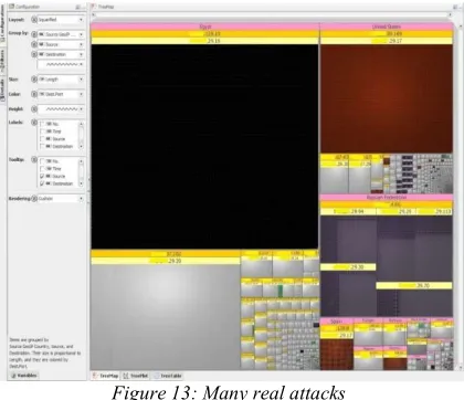
Figure 13: Many real attacks
In Figure 13 the proposed system observed many attacks, from which violent attack of denial of service came from Egypt from source x.x.128.19 aimed the server that has IP x.x.29.16 over port 64377. In the same figure, the system detects bomb mail attack from the USA, aimed the mail server that; the attacker sends many emails to the victim. 5.3 Comparison with other Schemes
[image:13.612.91.297.241.403.2]Finally, compared to the most famous previous systems, our system has higher capacity to discover the more different threats as shown Table 10.
Table 10 : Attack detection comparison to other related work
O ur S ys te m N V is io nI P [3 ] N et B yt es [4 ] V is ua l[ 5] N Fl ow V is [7 ] Y el iz ar ov a nd G am ay un ov [9 ] SV is io n[ 10 ] T he S pi nn in g C ub e of P ot en ti al D oo m [9 ] A bd ul la h et a l.[ 9] H os t N et w or k (H oN e) [ 9] Po rt al l[ 9] System/ Attack √ × × × × × × × × √ √ Spyware √ × × × × × × × × √ √ ad-wares √ √ × × × × √ √ × × × Port Sweep √ √ × × × × √ × × × × IP Sweep √ × × √ × × × × × × × Ping Sweep √ √ √ √ × × √ × × × × DOS √ × × × √ * × √ × × × × DDOS √ √ × × √ × × × √ × × Botnet traffic √ × × × × × √ × × × × Zero-Day Attack √ × × × × × × √ × × × solo attacks √ × × × × √ √ × × × × Multistep attacks × √ × × × × × × × × × Worm
* (SSH attacks)
[image:13.612.105.506.481.690.2]202 6. USABILITY
EVALUATION
In the usability test for the proposed system we wanted to evaluate the ease of system usage and how it helps network security administrator to detect attacks. Thirty experts in the science of network security were selected to participate in the usability experiment. We divide our participants into two groups. The first group is the network technician team in our university. The second group works in the same field in many other locations in the country. We selected two of the related work: VISUAL [5] and Abdullah et al.[13] to compare their usability to that of our proposed system. VISUAL [5] is selected as it focus on the relation between internal and external hosts. Abdullah et al.[13] is selected as it focus on the port usage. Before the test session, we briefly explained to the participants the three systems.
Standard version of the (SUS)[33] questions is used. The SUS consists of ten items questionnaire with five scale steps each.
Everyone answers ten questions; these answers will range from 0 to 4. For positive questions (odd numbers), the score contribution is the scale position minus 1 (xi – 1). For negative questions (even
numbers), the score contribution is five minus the scale position (5 – xi). To get the overall SUS score,
we multiply the sum of the item score contributions by 2.5. Thus, overall SUS scores range from 0 to 100 in 2.5-point increments.
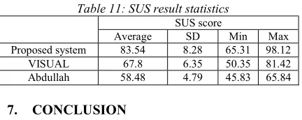
[image:14.612.313.524.322.509.2]A SUS score comparison between VISUAL [5], Abdullah et al.[13] and proposed scheme is shown in Figure 14. The comparison shows that proposed scheme has a better usability than VISUAL [5] and Abdullah et al.[13]. Also, Table 11 shows that the average SUS score from all 30 participants for VISUAL [5], Abdullah et al.[13] is a 67.8 and 58.48 respectively and our proposed scheme score 83.54. A SUS score above a 68 would be considered above average.
Table 11: SUS result statistics
SUS score
Average SD Min Max
Proposed system 83.54 8.28 65.31 98.12
VISUAL 67.8 6.35 50.35 81.42
Abdullah 58.48 4.79 45.83 65.84
7. CONCLUSION
This paper explained motivations for using information visualization with network traffic for security purposes. The research performed to come
up with our scheme included an explanation of Treemap, geolocation database, Squarified algorithm to arrange attributes and CMC algorithm for color. Our proposed scheme displays many network traffic attributes a grouped the destination ports based on its usage. Destination ports are encoded using CMC color differencing algorithm which produces distinct color within a certain tolerance. The proposed scheme shows both port activities and internal/external hosts representation in the same graph. This allows our visualization system to detect a wide variety of interesting security events. Finally, the proposed scheme makes use of Akamai Content Delivery Network to represent countries. To evaluate the usability of the proposed scheme, a prototype is implemented as a java application. The analysis of the proposed scheme shows that it achieves a high level of usability while satisfying the security requirements.
Figure 14: SUS core comparison between Visual, Abdullah, and Proposed system
REFRENCES:
[1] M. F. Bradley Huffaker, kc claffy, "Geocompare: a comparison of public and commercial geolocation databases," 2011. [2] Akamai. http://www.akamai.com/- reports.
Available: http://www.akamai.com/- reports [3] L. Kiran, B. Ratna, A. Slagell, W. Yurcik, and
S. North, "Closing-the-loop in NVisionIP: integrating discovery and search in security visualizations," in IEEE Workshop on Visualization for Computer Security, 2005. (VizSEC 05). 2005, pp. 75-82.
[4] S. B. T. Taylor, and J. McHugh, "Netbytes Viewer: An Entitybased Netflow Visualization
0.00 10.00 20.00 30.00 40.00 50.00 60.00 70.00 80.00 90.00 100.00
1 3 5 7 9 11131517192123252729
[image:14.612.85.301.602.688.2]203 Utility for Identifying Intrusive Behavior," 2008.
[5] "Ball R, Fink G A, North C (2004) Home-centric visualization of network traffic for security administration. Proceedings of the 2004 ACM Workshop on Visualization and Data Mining for Computer Security, 55–64." [6] R. Marty, Applied Security Visualization:
Addison-Wesley, 2009.
[7] F. Fischer, F. Mansmann, D. A. Keim, S. Pietzko, and M. Waldvogel, "Large-scale network monitoring for visual analysis of attacks," in Visualization for Computer Security, ed: Springer, 2008, pp. 111-118. [8] A. Yelizarov and D. Gamayunov,
"Visualization of complex attacks and state of attacked network," in Visualization for Cyber Security, 2009. VizSec 2009. 6th International Workshop on, 2009, pp. 1-9.
[9] H. Shiravi, A. Shiravi, and A. A. Ghorbani, "A survey of visualization systems for network security," IEEE Trans Vis Comput Graph, vol. 18, pp. 1313-29, Aug 2012.
[10] I.-V. Onut and A. A. Ghorbani, "SVision: A novel visual network-anomaly identification technique," computers & security, vol. 26, pp. 201-212, 2007.
[11] M. Bruls, K. Huizing, and J. J. Van Wijk, "Squarified treemaps," in Data Visualization 2000, ed: Springer Vienna, 2000, pp. 33-42. [12] S. Lau, "The Spinning Cube of Potential
Doom," Commun. ACM, vol. 47, pp. 25-26, 2004.
[13] A. Kulsoom, C. Lee, G. Conti, and J. A. Copeland, "Visualizing Network Data for Intrusion Detection," in Proceedings from the Sixth Annual IEEE SMC Information Assurance Workshop, 2005, pp. 100-108.
[14] G. A. Fink, V. Duggirala, R. Correa, and C. North, "Bridging the Host-Network Divide: Survey, Taxonomy, and Solution," in LISA, 2006, pp. 247-262.
[15] G. A. Fink, "Visual Correlation of Network Traffic and Host Processes for Computer Security," 2005.
[16] (2001). Color Measurement Committee. Available: http://www.brucelindbloom.com [17] D. Heggie, R. H. Wardman, and M. R. Luo, "A
comparison of the colour differences computed using the CIE94, CMC(l:c) and BFD(l:c) formulae," Journal of the Society of Dyers and Colourists, vol. 112, pp. 264-269, 1996. [18] S. Institute. (2016). The Center for Internet
Security Critical Security Controls V6.0. Available: https://www.cisecurity.org/controls/
[19] WinPCap: The Windows Packet Capture Library. http://www.winpcap.org.
[20] W. Mokrzycki and M. Tatol, "Colour difference∆ E–A survey," Machine Graphic & Vision, vol. 8, 2012.
[21] R. McDonald, "Acceptability and Perceptibility Decisions Using the CMC Color Difference Formula," Textile Chemist & Colorist, vol. 20, 1988.
[22] M. L. GeoIP., "http://www.maxmind.com," 2010.
[23] D. B. a. L. Girardin. (2000). Macrofocus Treemap. Available: www.treemap.com [24] D. Lee, B. E. Carpenter, and N. Brownlee,
"Observations of UDP to TCP Ratio and Port Numbers," in 2010 Fifth International Conference on Internet Monitoring and Protection, 2010, pp. 99-104.
[25] Oriyano, CEH v8: Certified Ethical Hacker Version 8 Study Guide: Sybex, 2014.
[26] S.-P. Oriyano, CEH v9: Certified Ethical Hacker Version 9 Study Guide: John Wiley & Sons, 2016.
[27] E. C. Lo and M. Marchand, "Security audit: a case study [information systems]," in Electrical and Computer Engineering, 2004. Canadian Conference on, 2004, pp. 193-196.
[28] advanced port scanner. Available: https://www.advanced-port-scanner.com/ [29] S. Rahalkar, Certified Ethical Hacker (CEH)
Foundation Guide 1st ed. Edition: 2016. [30] EC-Council, Ethical Hacking and
Countermeasures: Secure Network Infrastructures, 2009.
[31] J. Fonseca, M. Vieira, and H. Madeira, "Testing and Comparing Web Vulnerability Scanning Tools for SQL Injection and XSS Attacks," in
13th Pacific Rim International Symposium on Dependable Computing (PRDC 2007), 2007, pp. 365-372.
[32] N. Antunes and M. Vieira, "Detecting SQL Injection Vulnerabilities in Web Services," in
2009 Fourth Latin-American Symposium on Dependable Computing, 2009, pp. 17-24. [33] J. Sauro and J. R. Lewis, Quantifying the User
![Table 1: Top originating countries that represent the top attack traffic from 1st quarter in 2013 to 1st quarter in 2017[2]](https://thumb-us.123doks.com/thumbv2/123dok_us/8905179.956483/3.612.89.304.71.192/table-originating-countries-represent-attack-traffic-quarter-quarter.webp)
![Table 2: Geolocation database accuracy [1]](https://thumb-us.123doks.com/thumbv2/123dok_us/8905179.956483/4.612.125.491.364.468/table-geolocation-database-accuracy.webp)

![Figure 7: Advanced Port Scanning tool [28]](https://thumb-us.123doks.com/thumbv2/123dok_us/8905179.956483/11.612.314.527.287.464/figure-advanced-port-scanning-tool.webp)