Design, Simulation and Implementation of the
Ethernet Simplified MAC together with the P2MP
Emulation Layer for EPON ONU Devices
Mohammad Abdul Moniem Ali Ismael
Ain Shams University Prince Sultan Advanced Technology
& Research Institute (PSATRI)
Abd El-Haleem Zekry
Ain Shams University Faculty of Engineering
ECE Department
ABSTRACT
The market demand for providing higher bit rate within the access network has raised the requirement of deploying the Ethernet Passive Optical Network (EPON) to replace the old technology based on Digital Subscriber Line (DSL) and Cable Modem (CM). This paper presents the design, simulation and implementation of the Simplified Ethernet Medium access Controller (MAC) together with the Point-To-Multi-Point (P2MP) emulation mechanism that can be used for Optical Network Unit (ONU) devices.
Keywords
:
Ethernet Passive Optical Network,Ethernet-In-The-First-Mile, IEEE 802.3ah, Fiber-To-The-Home, Medium Access Controller, Point-To-Multi-Point Emulation, Optical Network Unit.
1.
INTRODUCTION
Improving the data bit rate within the access network (known as the first mile) requires to replace the old copper-based cables; with its associated DSL & CM technologies; by fiber lines that can provide speeds up to 1000Mbps. Basically, there are two kinds of the optical fiber networks; passive and active; The Passive Optical Network (PON) has a major advantage that it utilizes a non-active part called “Passive Optical Splitter” that doesn’t consume electrical power which makes it easy to be built and maintained, This is why the PON is preferred for future deployment[1].
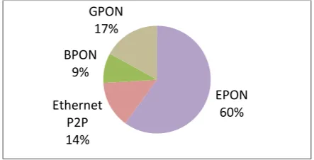
[image:1.595.316.544.576.733.2]Several data protocols can be used with the PON networks. But according to a market study that had been conducted on 2009 by IDATE[2], The Asian market players in Japan, South Korea and China have leaded the rapid growth of the EPON technology that currently occupies about 60% out of the worldwide FTTx deployment as shown by Figure 1.
Figure 1: Breakdown of FTTx technologies around the globe at the end of 2009
EPON is a combination between the PON technology and the Ethernet-In-the-First-Mile “EFM” technology[3, 4] that was standardized by the IEEE802.3ah task force group. The EFM is architecturally mapped to the Open System Interconnection (OSI) reference model as shown by Figure
2
from which we can see the DLL layer consists of the Logic Link Control (LLC) sublayer, the Media Access Control (MAC) sublayer, Multipoint control protocol (MPCP) sublayer and an optional Operations, Administration, and Maintenance (OAM) sublayer[5].In order to make use of the widely used cheap Ethernet software and hardware equipments, the EFM standard guaranteed the compatibility with the traditional Ethernet architecture by extending the function of the Reconciliation sublayer (RS); located just under the MAC; to handle the so-called Point-To-Multi-Point “P2MP” emulation mechanism which integrates the Logical Link ID (LLID) tag within the frame preamble. Thus the EPON medium can behave as a collection of point-to-point links. This unique LLID is assigned by the OLT to each ONU once the registration process is completed[5].
This paper presents the design, simulation and implementation of the Simplified Ethernet Medium access Controller (MAC) that can be used for Optical Network Unit (ONU) devices. This MAC IP has advantages over the general MAC cores used for LAN networks as it involves the design of the P2MP emulation layer; besides performing VLAN-based insertion/filtration in hardware not in software.
Figure 2: Mapping OSI model to both P2P and P2MP topologies of the EFM networks
EPON 60% Ethernet
P2P 14% BPON
9% GPON
[image:1.595.56.278.604.717.2]In addition, this MAC works only in full duplex mode with a single speed of 1000Mbps and a single PHY interface of GMII which optimally decreases the FPGA resources utilization. Finally, being an open-source MAC, it can help with the future research of designing other EPON sublayers like the MPCP, OAM and AES security. These sublayers are better implemented in hardware as well[6-8].
2.
FUNCTIONAL DESCRITION
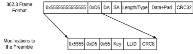
The EFM standard introduced some adaptations to the Ethernet frame format by adding a significant amount of information to its preamble field[9]; as depicted by Figure
3
; the third byte has changed to carry the value of 0xD5 that represents the Start of LLID Delimiter (SLD). The fifth byte carries the “key” that indicates the session number which is used for security issues (Encryption and decryption). The LLID tag; besides the mode bit; has been assigned to the sixth and seventh bytes. Finally, the eighth byte has changed to contain the CRC8 value that is computed for the preamble starting from the first bit of the SLD through the last bit of the LLID [9]. Otherwise, the remaining bytes; first, second and fourth; have been left unaltered and will still be transmitted as 0x55.0x55555555555555 0xD5DA SALength/Type Data+Pad CRC32
0x5555 0xD5 0x55 LLID CRC8 802.3 Frame
Format
Modifications to
[image:2.595.322.533.121.498.2]the Preamble Key
Figure 3: Modifications to the Ethernet frame format
The function of the P2MP Emulation can be summarized as the following[5]
- In case of frame transmission, The Emulation layer replaces the old preamble field by the new preamble which contains the SLD, key, LLID and the CRC8 fields.
- In case of frame reception,the emulation layer maps the new preamble to the old fixed pattern preamble as well as checking the value of the LLID tag and the CRC8 field. If the LLID doesn’t match with the local value assigned by the host processor after the registration process; then the emulation layer discards this frame. If there is a CRC error the frame will be discarded as well.
The rest of the EPON frame involves the common Ethernet fields like the Destination and source MAC addresses, the data length or type, the Data payload and finally the Frame check sequence. The least significant bit (LSB) of the destination address is used to determine unicast “0” or multicast “1”. Also the FCS field contains the CRC32 value computed starting from the destination address field.
3.
HW DESIGN PHASES
[image:2.595.326.532.177.369.2] [image:2.595.68.265.318.373.2] [image:2.595.341.520.365.469.2]3.1
System structural design
Figure
4
illustrates the structural design of the system showing the main building blocks as well as the interfaces with adjacent layers. Basically, the system consists of a register file, the simplified MAC core, P2MP emulation layer, the MDIO management module and finally 2 modules for loopback on both PHY and streaming sides.The EPON simplified MAC implements all functional requirements of the MAC as stated by the IEEE 802.3ah standard and described by the annex 4A [5]. The structural design of this simplified MAC is shown by Figure
5
whichillustrates the internal components like theTxand Rx finite state machines that are used to achieve the transmission & reception of the Ethernet frames. In addition, it contains Cyclic Redundancy Check “CRC” modules to generate and check the whole frame (CRC32) or part of the frame (CRC6 and CRC8). Also, there is a byte counter associated with each FSM to track the number of transmitted/received octets. This byte counter is also used when making any transition between the sub-states.
Register File (CSR)
Management ST Sink
MM Slave
Rx GMII
MDIO ST
Loop back ST Source
Tx GMII
PHY Loopback
P2MP Emulation Layer
GMII ST Interface Simplified
MAC
Rx GMII Tx GMII
MM Master
Figure 4: System structural design
Simplified Rx MAC
FSM
CRC32 Chk
CRC6 Chk Simplified
Tx MAC FSM CRC32
Gen
Byte Counter Byte
Counter
Figure 5: Structural design of the simplified MAC
As explained earlier, The P2MP Emulation layer implements the required mapping for the new preamble field to match the old fixed pattern of the Ethernet frame. It mainly containsTxand Rx Finite State Machines with a CRC8 generator and checker as shown by Figure
6
.CRC8 Gen
CRC8 Chk
Tx P2MP Rx P2MP
Figure 6: Structural design of the P2MP emulation layer
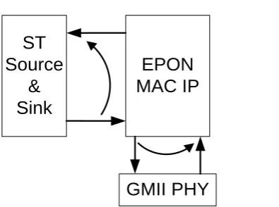
Finally, The ST/PHY loopback blocks are used to test and troubleshoot the design functionality by looping the data back on both streaming and PHY sides.
Two flavors of the Avalon busare used for this system;first one is the Memory Mapped “MM” Master & Slave interfaces while the second one is the Streaming “ST” Source & Sink interfaces.
The “MM Slave” bus is mastered by the host to access the registers set (control & status) of the MAC. This is the control bus that enables the host to configure the IP by accessing its address space to provide the required options for bothTxand Rx operations as well as reading the status after each transaction.The “MM Master” bus is used by the MAC to access the hash and VLAN tables pre-initialized by the host. These tables are used to classify the received frames.
The ST Streaming interface is the interface on which data streams from the LLC downto the MAC forTxdirection and from the MAC upto the LLC for Rx Direction. It is simply a FIFO interface contains an ; synchronized with the that is provided by the PHY; as well as 5 control signals called start of packet (), End Of Packet (), , and signals. This design assumes using external Tx& Rx FIFOs as well as external Tx& Rx DMA engines within the LLC layer. The FIFOs are used to queue the data coming from the upper software layers for transmission and also to queue the data coming from the MAC in the receive path.
The GMII interface with the PHY includes a dedicated receive bus and a dedicated transmit bus (full duplex operation). Each bus contains 8 bits of data together with “ and “ control signals besides a status signal. These two data buses are synchronized withTxand Rx clocks provided by the PHY chip and operating at 125MHz. In addition, The GMII involves the serial management interface that is used to access the control and status register of the PHY through 2-wire interface consistsof a clock pin and an in/out data pin.
The relations between the EPON frame fields with the PHY and ST control signals are presented by Figure
7
and Figure8
for frame transmission and reception respectively.
SOP EOP
0x55555D55 CRC8DA SA Length/TypeData & Pad CRC IFG Rdy
ST Side
PHY Side
Err
Tx_Err Go to IDLE Rdy ~Rdy Rdy
~CRS ~Rdy
~Rdy
IDLE Key LLID
En
[image:3.595.326.537.389.455.2]~En
Figure 7: ST & PHY Control signals for frame transmission
0x55555D55 CRC8DASALength/Type Data & Pdding CRC
DV ~DV
SOP
RX_ER Rdy
EOP
ST Side
PHY Side
Err
EOP (optional)
IDLE Key LLID DV
Figure 8: ST& PHY Control signals for frame reception
3.2
Components design
Our EPON MAC IP mainly contains four finite state machines. Two of them used to design the simplified MAC while the other two are used to design the emulation layer. These four state machines are depicted by Figure
9
, 10, 11 and 12.Generally, in each state, the system controls the output signals to the PHY, ST source and the CRC modules besides calculating local registers and statistical counters which are used for error check during data flow.
For every state machine: When receiving a reset signal, getting global error interrupt from the host or the PHY, or when it recovers from any unknown state, each state machine starts at itsappropriate initial state.
For every state machine: The transitions are done mainly by the control signals coming from both ST and PHY sides. Additionally, an internal counter is used to holdthe total number of bytes processed. This counter is being incremented every Byte is sent/received. When it reaches the value of the field width (e.g. width of the CRC field is 4 bytes) the system exits from its current state and moves to the next state. Also this counter is initialized to zero during any transition.
3.2.1
The simplified Tx MAC
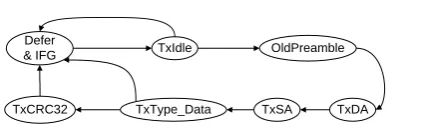
[image:3.595.63.275.461.613.2]The state transition of the simplified Tx MAC is shown by Figure
9
; we can see it starts with the state waiting for the PHY to get ready and for the IFG period to pass. Then it moves to the state to initialize all output signals as well as all local registers.When it receives a SOP from the ST side, it sends the fixed pattern of the old preamblethen it moves to the state. During both and states the system is transparent and it just forwards the data stream from the ST source down to the Tx P2MP layer. In addition the system can parse the data stream and recognizes the type of the destination address (unicast, multicast or broadcast) to be used for incrementing the appropriate counters.
TxDA TxSA
TxType_Data TxCRC32
OldPreamble TxIdle
Defer & IFG
Figure 9: Transmission state diagram
In the state, the Tx MAC sends the Source address “” which is provided by the host within the register file if that option is enabled. Otherwise, it acts transparently and forwards the SA coming from the data stream.
Inside the state, the system sends the CRC32 value calculated during the frame transmission starting from the
state.
3.2.2
The Tx P2MP layer
TxKey TxLLID TxCRC8
[image:4.595.56.285.72.267.2]TxData _0x55555D55 TxIdle
Figure 10:TxP2MP layer
3.2.3
The simplified Rx MAC
RxDA RxSA
RxCRC32
OldPreamble RxIdle
RxType RxData
VLAN
SVLAN
Figure 11: Reception state diagram
[image:4.595.330.528.557.704.2]The state transition of the simplified Rx MAC is shown by Figure 11; we can see it starts with state inside which all output signals are initialized. It deactivates the , and signals going to the ST sink. Also the CRC32 checker is disabled and initialized to all 1’s. In addition all local registers are set to the reset values.
When it receives signal from the Rx P2MP layer, it moves to the state to receive the fixed pattern of
then it moves to the state inside which it receives the destination address and starts to calculate the CRC32 that will be used at the end of frame reception for error check. In addition, itcalculates the CRC6 of the received address to be used as an entry to the hash table configured earlier by the host. Then accordingly the frame is decided to be accepted or discarded based on the first bit of the read word from the hash table. The frame is also accepted if the destination address equals the local Unicasting value or if it equals the broadcasting value (all ones).
In the state, the Simplified Rx MACreceives the source address “” from the PHY and forwards it to the ST sink. In the state, the Simplified Rx MACrecognizes the frame type and moves to the VLAN state if the frame type is
.
Inside the VLAN state, the Simplified Rx MAC captures the values of the VLAN tag and the VLAN Length/type and stores them into local registers to be used later during the exit transition from the state.
The simplified Tx MAC moves to the SVLAN state if the VLAN type equals (stacked VLAN) otherwise it moves to the RxData state.
Inside the SVLAN state, the Simplified Rx MAC does similar operations but this time it recognize and stores the values of the stacked VLAN tag and length.
In the state, the Simplified Rx MACacts transparently between the ST sink and the Rx P2MP layer; where the data coming from the Rx P2MP layer is sent directly to the ST sink.
Atthe end of the frame (In the state), the Simplified Rx MACcontinues to calculate the CRC32 for the field.
If any of the following conditions occurs, the simplified RxMAC will moveto the state and will terminate the reception by sending the corresponding error signal to the ST sink
• Received destination address doesn’t match any of the unicast, multicast or broadcast addresses.
• Frame length is higher than the max allowed value.
• CRC error is received by the CRC checker at the end of the data stream.
3.2.4
The Rx P2MP layer
Figure 12 shows the state transition of the Rx P2MP layer which starts in the state. Then when it receives a “DV” signal from the PHY it moves to the “” state to receive the fixed pattern of the new preamble followed by the Encryption key and LLID tag (MSB first then the LSB). the received LLID is considered a match under the following criteria[5]
• If the received mode bit is 0 and the received LLID value matches the local LLID provided by the host within the register file.
• If the received mode bit is 1 and the received LLID value does not match the local LLID, or the received LLID matches 0x7FFF.
RxKey RxLLID RxCRC8
RxData Rx_0x55555D55
RxIdle
Figure 12: Rx P2MP layer
After the state, it moves to the “” state to check the received CRC8 field versus the locally calculated value starting from the SLD byte (0x5D).
3.2.5
The Loopback Facilities
Two loopback facilities are considered as shown by Figure 13
.
By these loopback blocks, we can test and troubleshoot the design functionality by looping the data back on both streaming and PHY interfaces.EPON
MAC IP
ST
Source
&
Sink
GMII PHY
3.2.6
CRC generators/Checkers
For the EPON MAC IP, Many CRC algorithms are utilized to check the integrity of the whole frame (CRC32) or certain fields of the frame (CRC8 and CRC6); The CRC32 forms the value of the field which is used to check the whole frame has been received with no error. While CRC8 forms the value of the last byte of the preamble as described earlier, finally the CRC6 algorithm is used with the hash tables applied on the MAC destination address as well as the type of the frame. During the frame reception and after recognizing the multicasting destination address, the Rx MAC calculates the CRC6 of this address and takes the result as an entry to the hash table. If the first bit of the read word is “1” so the frame is accepted and not discarded.
We initialized the CRC register to all zeros for both CRC8 & CRC6 calculations. But for CRC32 we initialized it to all ones to follow the standard recommendations[5], Also, Instead of calculating the CRC and comparing it with the coming value; the Rx MAC calculates the CRC32 on the whole packet then if the result is the magic number that means there is no error. The parallel implementation of the CRC32, CRC8 and CRC6 algorithms can be obtained from many online tools. For our EPON MAC IP, we used the tool in [10] to generate the Verilog functions that we have used.
3.2.7
The management module
This module has been implemented in very efficient way by using 2 bits within the register file to drive the data and clock signals while the protocol that handles the data format is completely done by SW as part of the device driver.
4.
SIMULATION & RESULTS
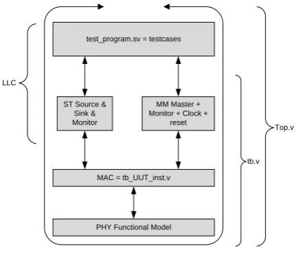
The Altera SOPC system integration tool has been used to build the testbench; shown by Figure 14
;
which contains the following modules:i. The EPON MAC IP: which is the Unit-Under-Test “UUT”.
ii. Functional model of the PHY: This simulation model has been developed in Verilog to behave similarly as the gigabit physical layer with GMII interface. This model can send and receive simultaneously; it contains all required processes, functions and tasks to send and receive the Ethernet frames as well as appending/checking the values of the CRC fields.
iii. Avalon Bus functional models “BFM”:which are Available within the Altera Qsys/SOPC tools that provides the Streaming Source & Sink, Streaming monitor, Memory-Mapped Master & Slave and the Memory-Mapped Monitor
iv. The “Tester Program”: which we have written in SystemVerilog to perform different testcases. We utilized the Application Programming Interface functions “API’s” that are provided with the Altera ST and MM bus functional models.
The whole design has been simulated and verified by the widely used Modelsim6.6 tool from Mentor Company; the simulation results showed that the design has realized the related functions properly. Some basic simulation results will be discussed here by the following paragraphs.
PHY Functional Model MAC = tb_UUT_inst.v ST Source &
Sink & Monitor
MM Master + Monitor + Clock +
reset test_program.sv = testcases
LLC
Top.v
[image:5.595.318.534.73.257.2]tb.v
Figure 14: Structure of the testbench
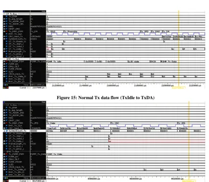
Figure 15 depicts aTxstreaming transaction from the state till the beginning of the state. As we can see the Simplified Tx MAC is ready in the TxIdlestate but when the ST source starts a new frame (by setting the signal) the Txmodule becomes not ready until sending theP2MP preamble fields that contains the tag and the value.We can observe that calculating the CRC8 has started at the beginning of the byte of. Also we can observe that calculation has started by the beginning of sending the destination address. In addition, we can observe that the first 2 bytes of the has been handled properly without any data loss.
As shown by Figure 16, the Simplified Tx MAC enters the
state when the ST source finishes sending the frame data (by activating the signal) then it sends the inverted version of the calculated to the PHY byte by byte. Also we can observe that the Simplified Tx MAC has continued the CRC calculation which results the magic number “of value ” at the beginning of the
state.
Figure 17 shows a normal Rx data flow; where it starts when the PHY sets the “” signal and puts the preamble on the Rx GMII bus, the Simplified Rx MAC moves from the
state to the state to receive the preamble (2 bytes of “” followed by the “” followed by 2 bytes of “” followed by the and finally the
Figure 18 shows the end of the frame reception; the PHY sends the value of the CRC32. The Simplified Rx MAC has generated the magic number () at the end which means the frame has been received properly and it is clear from errors. Then the Simplified Rx MAC terminated the stream normally and has set the “” signal to the ST sink. After that, the system moved to the “” state in which it has deactivated the “” & “” signals going to the ST sink
5.
FPGA IMPLEMENTATION
The whole system has been implemented onto a Stratix IV FPGA device “EP4SGX530NF45C4” using the flow provided by Altera Quartus II version 11 that has reported the results shown by Table 1, 2 and 3.
Table 1: Achieved FmaxVs requirements
Clock Required
(MHz)
Max Achievable (MHz)
Pll.c1 = PHY Tx clk 125 185.49
PHY Rx Clk 125 132.61
Table 2: Resources utilization by entity
Module Combinational ALUT Registers Logic
Block memory
bits
Register File 635 448 0
Rx MAC 1458 762 0
Tx MAC 1006 356 0
Rx Emulation 26 19 0
Tx Emulation 121 50 0
Hash Table 1 0 2048
VLAN Table 2 0 32768
Table 3: Power analysis
Module Thermal Dynamic Power (mW)
Routing Thermal Power (mW)
Register File 1.69 1.68
Rx MAC 5.57 6.6
Tx MAC 3.84 3.21
Rx Emulation 0.11 0.07
Tx Emulation 0.44 0.17
Hash Table 2.06 0.03
VLAN Table 4.29 0.11
[image:6.595.94.504.328.684.2]Figure 15: Normal Tx data flow (TxIdle to TxDA)
Figure 17: Normal receive Case (from RxIdle to RxDA)
Figure 18: Normal receive Case (FCS field)
6.
CONCLUSION
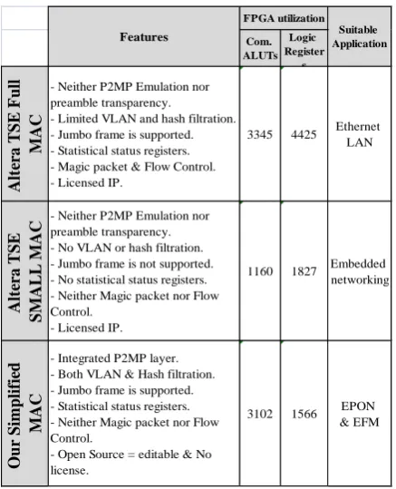
In order to characterize our design performance we can compare it with the well-known Triple Speed Ethernet “TSE” IP core from Altera. There are 2 basic variations from the TSE MAC called "Full MAC" and "Small MAC". The "Full MAC" can work with the triple speeds of 10/100/1000 Mbps in both half and full duplex modes with MII/GMII/RGMII interfaces. While the "Small MAC" works only with a single speed of either 10/100 or 1000 Mbps in only full duplex mode with only one interface to the PHY which is either MII, GMII or RGMII. In addition, The "Full MAC" is fully programmable and fully configurable to support features like VLAN detection, Multicasting hash tables, Flow control, Magic packet, Jumbo frames, frame length set and check and setting the IFG period. But for the "Small MAC" these features are not supported. To compare our design versus these 2 variations from Altera, We first talk about the target application that is suitable for each one; The Altera variations were designed mainly according to the IEEE 802.3 standard which is not fully matched with the Ethernet-In-The-First-Mile EFM standard (IEEE 802.3ah). So these variations are better used for Ethernet LAN networking but still don't fit the EFM application because of the following reasons:
•They don't contain the P2MP emulation layer that deals with the LLID, Encryption key and CRC8 fields that are embedded within the EFM preamble. Also, it suppresses the preamble and doesn't pass it transparently to the upper layers which means the P2MP operations can't be done by the upper SW layers.
•For EPON application there is a mandatory requirement for both ONU and OLT devices to be able to do Insertion/Filtration based on VLAN tags, MAC addresses, IP addresses and frame length. These requirements are absent in the small MAC and limited in the Full MAC. Although we can see the "Full MAC" variation supports the VLAN detection but it just detects it and sends it to the upper SW layer without taking any Insertion or Filtration action.
•From the prospective of the FPGA resources utilization, we can see from Table 4 that oursimplified MAC (excluding the emulation and VLAN/Hash tables)is located between the Small and Full MAC variations. Because it can be considered that we have implemented a small MAC besides the features required for EPON networks and we haven’t implemented the non-useful features that are used by the Full MAC like magic packet detection, flow control, half duplex mode and other MII/RGMII interfaces.
So, we can conclude that, we could design, simulate and implement an optimum MAC IP targeted at the EPON application with efficient resources utilization.This work can be considered as the first step taken to design and implement Ethernet networking devices (ONU and OLT) in the level of theFTTx subscriber access network. The next step is to design and implement the other DLL sublayers which are MPCP, OAM, FEC and AES Security.
Table 4: Comparing the resources utilization Vs Altera’s Small and Full MAC variations
Com. ALUTs
Logic Register
s
A
lt
er
a T
S
E
F
u
ll
M
A
C
- Neither P2MP Emulation nor preamble transparency.
- Limited VLAN and hash filtration. - Jumbo frame is supported. - Statistical status registers. - Magic packet & Flow Control. - Licensed IP.
3345 4425 Ethernet LAN
A
lt
er
a T
S
E
S
M
A
LL M
A
C - Neither P2MP Emulation nor preamble transparency. - No VLAN or hash filtration. - Jumbo frame is not supported. - No statistical status registers. - Neither Magic packet nor Flow Control.
- Licensed IP.
1160 1827 Embedded networking
Ou
r S
im
p
lif
ie
d
M
A
C
- Integrated P2MP layer. - Both VLAN & Hash filtration. - Jumbo frame is supported. - Statistical status registers. - Neither Magic packet nor Flow Control.
- Open Source = editable & No license.
3102 1566 EPON & EFM Suitable Application Features
FPGA utilization
7.
REFERENCES
[1] G. Kramer and G. Pesavento, "Ethernet passive optical network (EPON): Building a next-generation optical access network," Communications magazine, IEEE, vol. 40, pp. 66-73, 2002.
[2] IDATE. (2009). World FTTx Markets [www]. Available:
[3] C. F. Lam, Passive optical networks: principles and practice: Academic Press, 2007.
[4] J. S. Shaik and N. Patil, "FTTH deployment options for telecom operators," Sterlite Optical Technologies Ltd., White Paper, pp. 1-9, 2005.
[5] IEEE, "Carrier sense multiple access with collision detection (CSMA/CD) access method and physical layer specification," in IEEE Std 802.3-2002, ed. [IEEE 802.3], 2002.
[6] Z. Wang, et al., "MPCP design in prototyping optical network unit of ethernet in the first mile," 2004, pp. 121-125.
[7] F. Zhang, et al., "EPON ONU system design and implementation based on Spartan 6," 2011, pp. 2226-2229.
[8] J. Zou, et al., "Design and FPGA implementation of OLT for EPON," pp. 761-764.
[9] E. Lynskey, "Preamble modifications for 1000BASE-PX networks," ed.