http://dx.doi.org/10.4236/jpee.2015.37001
Development of a Fast Fluid-Structure
Coupling Technique for Wind Turbine
Computations
Matias Sessarego, Néstor Ramos-García, Wen Zhong Shen
Department of Wind Energy, Technical University of Denmark, Lyngby, Denmark Email: [email protected]
Received 24 March 2015; accepted 10 July 2015; published 17 July 2015
Abstract
Fluid-structure interaction simulations are routinely used in the wind energy industry to evaluate the aerodynamic and structural dynamic performance of wind turbines. Most aero-elastic codes in modern times implement a blade element momentum technique to model the rotor aerodynamics and a modal, multi-body, or finite-element approach to model the turbine structural dynamics. The present paper describes a novel fluid-structure coupling technique which combines a three- dimensional viscous-inviscid solver for horizontal-axis wind-turbine aerodynamics, called MIRAS, and the structural dynamics model used in the aero-elastic code FLEX5. The new code, MIRAS- FLEX, in general shows good agreement with the standard aero-elastic codes FLEX5 and FAST for various test cases. The structural model in MIRAS-FLEX acts to reduce the aerodynamic load com-puted by MIRAS, particularly near the tip and at high wind speeds.
Keywords
Fluid-Structure-Interaction, Wind-Turbine, Aero-Elasticity
1. Introduction
Fluid-structure interaction (FSI) is the mutual action and reaction between a moveable or deformable structure with an internal or surrounding fluid flow [1]. FSI simulations are routinely performed for the analysis of wind turbine operation in the wind energy industry using what are known as aero-elastic codes. Examples for hori-zontal-axis wind turbines (HAWTs) are FLEX5 [2], FAST [3], and HAWC2 [4]. Most aero-elastic codes in modern times implement a blade element momentum (BEM) technique to model the aerodynamics, see e.g. Hansen [5], while mode shapes [2], multibody dynamics or finite element techniques [4] are used for the struc-tural dynamic modelling. This paper presents a novel aero-elastic code that uses a three-dimensional (3D) visc-ous-inviscid solver for the aerodynamic analysis, called MIRAS [6], and a structural dynamic model based on mode shapes from FLEX5. The new code is called MIRAS-FLEX.
2. Description of MIRAS and FLEX5
2.1. MIRAS
Method for Interactive Rotor Aerodynamic Simulations, MIRAS, is a 3D viscous-inviscid solver for HAWT ro-tor computations. The solver predicts the aerodynamic behavior of wind turbine wakes and blades for steady and unsteady conditions. The MIRAS code consists of inviscid and viscous parts. The inviscid part is a 3D panel method using a surface distribution of quadrilateral sources and doublets. The inviscid part is coupled to the viscous part through a viscous boundary layer solver, Q3UIC [7]. A free-wake model simulates the wake behind the wind-turbine rotor using vortex filaments that carry the vorticity shed by the blades trailing edges. These features give MIRAS a more detailed aerodynamic description than the BEM technique and at a much lower computational cost than Navier-Stokes solvers. The reader is referred to [6] for a comprehensive description of MIRAS.
2.2. FLEX5
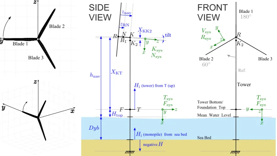
FLEX5 is an aero-elastic code that runs in the time-domain producing time-series of loads and deflections. The program relies on the BEM technique to model rotor aerodynamics, while the structural behavior of the wind turbine is modelled using carefully selected degrees of freedom (DOFs). The deflections of the blades and tower are given by shape functions, while the nacelle, rotor shaft, and hub are modelled as stiff bodies connected by flexible hinges. FLEX4 was originally developed with 17-20 DOFs and later upgraded to 28 DOFs in what is known as FLEX5. Figure 1 depicts the parameters and coordinate systems in MIRAS (left) and FLEX5 (right).
3. Coupling Methodology
3.1. Fluid-Structure-Interaction Terminology
[image:2.595.94.536.455.704.2]FSI problems can be solved by the monolithic or partitioned approaches. In the monolithic approach, the equa-tions governing fluid flow and structural displacement are solved simultaneously with a single solver. The mo-nolithic approach is advantageous in terms of stability because the mutual influence from the fluid and structural parts are taken into account [8]. However, a code needs to be developed incorporating both physical domains to allow a single solver to be used.
Conversely, the equations governing fluid flow and structural displacement in the partitioned approach are solved separately using two distinct solvers. Solving the equations from each domain separately means that the flow solution does not change while the solution of the structural part is being updated and vice versa. The parti-tioned approach allows existing computational codes to be used for each part of the FSI problem. Due to the se-quentially staggered approach, however, partitioned approaches are susceptible to stability and accuracy issues. Partitioned approaches require a carefully designed loosely- or strongly-coupled scheme for proper function.
Loosely coupled schemes require only one evaluation per time step, but are more likely to experience numer-ical instabilities than strongly-coupled schemes. Strongly-coupled schemes may have the same staggered solu-tion algorithm as loosely-coupled algorithms, but differ in that they perform sub-iterasolu-tions at each time step. The additional sub-iterations improves the stability, but at an additional computational cost. See [1] and [9] [10] for details on FSI.
3.2. Coupling Scheme
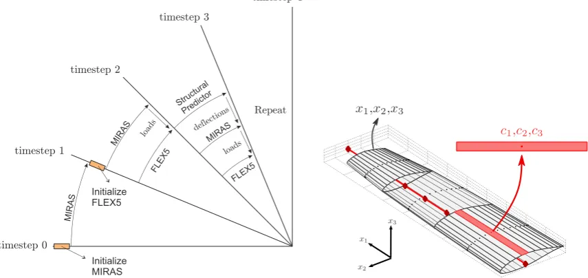
MIRAS and the dynamic model in FLEX5 are used for the fluid and structural parts, respectively, in a parti-tioned and loosely-coupled approach. Loose-coupling was chosen because the approach was successfully ap-plied to aero-elastic problems in [9] [10] and to make MIRAS-FLEX as computationally inexpensive as possible. Figure 2 depicts the coupling scheme in MIRAS-FLEX, which is similar to the ones used in [9] [10]. Only the blade DOFs are considered in the coupling, i.e. 1st and 2nd flap-wise and 1st edge-wise blade modes. Changes in the angle of attack in MIRAS due to blade motion are taken into account in the coupling.
3.3. Aerodynamic Load Transfer
Load transfer from MIRAS to FLEX5 is performed through interpolation between the 3D mesh of MIRAS (i.e.
1
x , x2 and x3) and the one-dimensional beam of FLEX5. Figure 2(right) illustrates the concept, where the loads defined at the center-points of each panel with coordinates c1, c2 and c3 from the MIRAS mesh are converted into equivalent loads in FLEX5 (diamonds). Both the beam in FLEX5 and the x1-axis in MIRAS coincide with the blade pitch-axis.
3.4. Deflection Transfer
FLEX5 uses Euler-Bernoulli beam theory (no torsion), see e.g. Bauchau and Craig [11], to predict the elastic deformation of the turbine blades. Thus, the displacement field of the blade cross-sections in MIRAS are based solely on rigid body translations (u1, u2 and u3) and rotations (φ2 and φ3):
[image:3.595.99.527.493.695.2]
(
)
( )
( )
( )
(
)
( )
(
)
( )
1 1 2 3 1 1 3 1 2 3 1
3 1 2 3 3
2
1
2 1 2 3 2 1
, , ,
, ,
, , ,
x x x u x x x x x
x x x u x u
u
u x x x u x
φ φ
= + −
=
= (1)
where u1, u2 and u3 are the total displacements and x1, x2 and x3 are the coordinates of the blade mesh, see Figure 2(right).
4. Simulations
4.1. Description of Simulation Tests
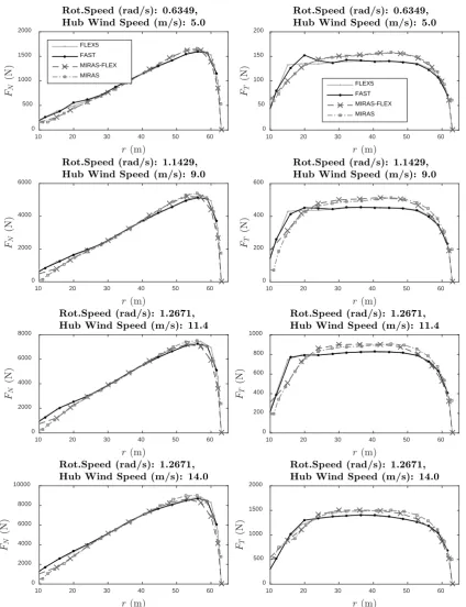
The NREL 5MW reference wind turbine [12] with a 126 m rotor diameter was chosen to perform simulation tests. Only steady wind conditions ranging from 5 to 14 m/s in an onshore environment are considered here. The tip-speed ratio is 8, pitch angle is 0, and the maximum rotational speed is 12.1 rpm. The codes used for the study are FLEX5, FAST, MIRAS-FLEX and MIRAS alone. For the FLEX5 simulations, the aerodynamics is eva-luated using the built-in BEM technique. FAST is included as a third-party code to validate MIRAS-FLEX and FLEX5. In Section 4.2, the aerodynamic loads normal
( )
FN and tangential( )
FT to the rotor plane are com-pared. All quantities are plotted versus the blade radius, r. Figure 3 displays the rotor wake of the MIRAS (left) and MIRAS-FLEX (right) simulations, where a total of 3000 mesh points (20 span-wise × 150 chord-wise) were used for each blade.4.2. Results and Discussion
All results are presented in Figure 4, which shows that MIRAS and MIRAS-FLEX are generally in good agreement with the standard aero-elastic codes FLEX5 and FAST. All results from FLEX5 and FAST are iden-tical because both implement the BEM technique for rotor aerodynamics and a modal approach for the structural dynamics. The tangential aerodynamic loads computed by MIRAS and MIRAS-FLEX are slightly higher than FLEX5 and FAST, especially at low wind speeds, because of the very distinct aerodynamic models used. As a consequence, the rotor torque in MIRAS and MIRAS-FLEX are also slightly higher than FLEX5 and FAST. In terms of the FSI coupling, the structural model in MIRAS-FLEX acts to reduce the aerodynamic load computed by MIRAS, particularly near the tip and at high wind speeds.
5. Conclusion
MIRAS has been coupled with FLEX5 using a partitioned and loosely-coupled methodology to predict the aero- elastic response of wind turbines. The novel code is called MIRAS-FLEX. In general, MIRAS-FLEX results are in good agreement with the standard aero-elastic codes FLEX5 and FAST. MIRAS and MIRAS-FLEX give higher values of tangential load in comparison with FLEX5 and FAST due to the distinct aerodynamic models used. MIRAS and MIRAS-FLEX implement a 3D viscous-inviscid solver, while FLEX5 and FAST relies on the blade element momentum technique. MIRAS-FLEX gives a lower prediction of loads in comparison with MIRAS, especially near the tip where deflections are the highest, due to the inclusion of structural dynamic modelling.
[image:4.595.118.508.588.701.2]
Figure 4. Comparison of the aerodynamic loads normal (left) and tangential (right) to the rotor plane computed by FLEX5, FAST, MIRAS-FLEX and MIRAS.
Acknowledgements
The present work was funded by the Danish Council for Strategic Research under the project name Off Wind China (Sagsnr. 0603-00506B). The support is gratefully acknowledged.
10 20 30 40 50 60
0 500 1000 1500 2000 FLEX5 FAST MIRAS-FLEX MIRAS
10 20 30 40 50 60
0 2000 4000 6000
10 20 30 40 50 60
0 2000 4000 6000 8000
10 20 30 40 50 60
0 2000 4000 6000 8000 10000
10 20 30 40 50 60
0 50 100 150 200 FLEX5 FAST MIRAS-FLEX MIRAS
10 20 30 40 50 60
0 200 400 600
10 20 30 40 50 60
0 200 400 600 800 1000
10 20 30 40 50 60
References
[1] Bungartz, H.J., Mehl, M. and Schäfer, M. (2010) Fluid Structure Interaction II: Modelling, Simulation, Optimization, 1439-7358. Springer Berlin Heidelberg, 53. http://dx.doi.org/10.1007/978-3-642-14206-2
[2] Øye, S. (1996) FLEX4 Simulation of Wind Turbine Dynamics. Proceedings of 28th IEA Meeting of Experts Concern-ing State of the Art of Aeroelastic Codes for Wind Turbine Calculations, Lyngby, 1996.
[3] NWTC Information Portal (FAST v8). https://nwtc.nrel.gov/FAST8
[4] Kim, T., Anders, A.M., Hansen, M. and Branner, K. (2013) Development of an Anisotropic Beam Finite Element for Composite Wind Turbine Blades in Multibody System. Renewable Energy, 59, 172-183.
http://dx.doi.org/10.1016/j.renene.2013.03.033
[5] Hansen, M.O.L. (2008) Aerodynamics of Wind Turbines. 2nd Edition, Earthscan, London.
[6] Ramos-García, N., Sørensen, J.N. and Shen, W.Z. (2014) Three-Dimensional Viscous-Inviscid Coupling Method for Wind Turbine Computations. Wind Energy. http://dx.doi.org/10.1002/we.1821
[7] Ramos-García, N., Sørensen, J.N. and Shen, W.Z. (2014) A Strong Viscous-Inviscid Interaction Model for Rotating Airfoils. Wind Energy, 17, 1957-1984. http://dx.doi.org/10.1002/we.1677
[8] Degroote, J., Bathe, K.J. and Vierendeels, J. (2009) Performance of a New Partitioned Procedure versus a Monolithic Procedure in Fluid-Structure Interaction. Computers & Structures, 87, 793-801.
http://dx.doi.org/10.1016/j.compstruc.2008.11.013
[9] Farhat, C., van der Zee, K.G. and Geuzaine, P. (2006) Provably Second-Order time-Accurate Loosely-Coupled Solu-tion Algorithms for Transient Nonlinear ComputaSolu-tional Aeroelasticity. Computer Methods in Applied Mechanics and Engineering, 195, 1973-2001. http://dx.doi.org/10.1016/j.cma.2004.11.031
[10] Heinz, J. (2013) Partitioned Fluid-Structure Interaction for Full Rotor Computations Using CFD. Ph.D. Thesis, Tech-nical University of Denmark, Denmark.
[11] Bauchau, O.A. and Craig, J.I., Eds. (2009) Structural Analysis: With Applications to Aerospace Structures, Solid Me-chanics and Its Applications. Springer Netherlands. http://dx.doi.org/10.1007/978-90-481-2516-6