3D Reconstruction using Interactive Shape from Shading
Mai Babiker Adm
Department of Computer and Information Sciences
Universiti Teknologi PETRONAS Tronoh, Perak, Malaysia
Abas Md Said
Department of Computer and Information Sciences
Universiti Teknologi PETRONAS Tronoh, Perak, Malaysia
ABSTRACT
The Shape-From-Shading (SFS) problem is a fundamental and classical problem in computer vision. It is the process of computing three dimensional shape of a surface using its shading information from single image. In this paper, a new method for interactive shape from shading for reconstruction of a 3D shape is presented. Experimental results on several synthetic and real object images show that the proposed method reconstructs the 3D surface of objects very efficiently.
General Terms
Shape from Shading (SfS), Fast Marching Algorithm (FMA).
Keywords
3D Lambertian, user interactive, module.
1.
INTRODUCTION
The 3D modeling is an interesting subject in computer graphics and image processing because of its wide applications in various fields such as model based compression coding, and computer assisted medical diagnosis and treatment. A single or more images can be used to obtain 3Dmodel of an object, taken simultaneously from different points of view (Stereo) or over a period of time (Video). Single image techniques rely on shading information, while multiple image techniques tend to use corresponding points and the parameters of the camera projection. To calculate depth information, most systems using a single image never use explicit 3D information to assist the modeling. Little work has been done to deal with the problem of 3Dmodeling of an object from a single image. The fine areas of these surfaces appear on the image as a variation of shading (depending on the object’s material). The methods that recover these features from the shading are called Shape-from-Shading (SfS), which is one of the attractive research fields in computer vision [1, 2, 3].
SfS deals with the recovery of surface orientation and surface shape (highlight) from the gradual variation of shading in images. SfS is implemented by first modeling the image brightness as a function of surface geometry and then reconstructing a surface which, under the given imaging model, generates an image close to the input image. This field was formally introduced by Horn [4] and there have been many significant improvements in both theoretical and practical aspects of the problem. However, it has been shown that this is an ill-posed problem [5, 6].
In this paper, we present an interactive shape from shading algorithm and show how it can be used for different materials. The aim is to retain the robustness and flexibility of using a user
interactive model for constructing a 3D surface from a single image. Furthermore the proposed approach supports computer graphics applications, such as:
medical applications, gaming,
image-based crime investigation, and recognition applications.
In this paper, we introduce an interactive shape from shading method for estimating the surface of 3D shapes. The remaining of this paper is organized as follows. Section 2 discusses some of the works related to our algorithm and lists the main advantages and limitations of each work. In section 3 we reveal our proposed interactive algorithm for shape from shading and the main steps of implementing it in computer graphics. Section 4 is dedicated for testing and validating our proposed algorithm of various 3D objects. The last section concludes this paper.
2.
RELATED WORKS
All the previous works are examples for non-interactive shape from shading. However, non-interactive method does not always produce satisfactory results especially in severe lighting condition. Because of this, interactive methods are used instead. Zeng et al. [7] proposed an interactive face reconstruction using shape from shading. They divided the face into smaller patches and estimated the surface of each patch by minimizing the patch energy function after smoothing it using fast marching method. The user interactively selects different points as new patch and the Voronoi method is used for segmenting each patch. Then the standard shape from shading method is processed for each patch. Meryer et al. [4] used an interactive model for shape from shading. Firstly the algorithm detects flat regions in the image which are the regions with highlights. Then the user interactively select whether these regions represent peaks or valleys. The depth of other points between peaks and valley is computed using mass-spring interpolation. This process is repeated until the user is satisfied with the resultant image.
3.
PROPOSED METHOD
Figure 1 shows our proposed interactive shape from shading framework. It starts with extracting the luminance from the image. Next, the depth gradient is computed from the luminance. Then, fast marching algorithm is used to smooth the computed depth map. The user interactive module interactively selects the regions with wrong depth estimation and helps in correcting it.
3.1
Luminance Extraction Module
The purpose of this module is to extract the luminance value by computing the shading image from the RGB colored image. The luminance represents the lighting component of the image. From an RGB image, the luminance is computed using the following equation [11, 12]:
3.2
Depth Gradient Formulation Module
The first step in depth gradient computation module is to solve the Eikonal equation which represents the luminance value as the inner product between surface normal and light source direction. In this work, we assume a vertical light source whose direction is the same as the viewing direction. This means, we only need to compute the surface normal that represents the image luminance. The surface normal is proportional to the depth gradient of the surface. Therefore the Eikonal equation (Eq. 2) [7] gives the relationship between light source direction and depth gradient in luminance value.
3.3
Fast Marching Algorithm Module
The Eikonal equation can be solved by the numerical algorithm called fast marching algorithm [4, 7]. The fast marching algorithm can be summarized in the following steps:
At initialization, all pixel altitudes Z(X,Y) are set to infinity
beside few pixels whose altitude are known.
All known pixels are put into a priority queue ordered by their altitude, smaller altitude first.
The algorithm extracts pixels from the priority queue until it is empty.
Starting from a known pixel, the altitude of its four connected neighbors is updated and added to the queue.
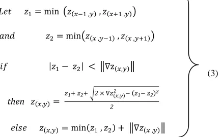
The altitude of pixel is updated as follows [4]:
(3) (3)
then
3.4
User Interactive Module
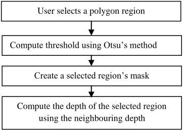
[image:2.612.49.253.374.592.2]After displaying the results obtained by the fast marching method, regions that have wrong depth map are selected by the user. It has been found that these are regions that have very bright or very dark colors. These regions are segmented based on the mean intensity value. Bright and dark regions are naturally peaks or valleys on the surface of the shape. Therefore, a suitable depth will be assigned to these regions based on the status of its neighboring regions. Figure 2 shows a flow diagram of the user interactive module. Firstly the user identifies a polygonal region to represent the region of problem. Then the threshold is computed using Otsu’s method and the region is
Fig 1: Interactive shape from shading framework. No
Yes
End Display module Input module
Luminance extraction module module
Depth gradient formulation module
Fast marching algorithm module
Satisfy? User interactive
[image:2.612.333.550.417.552.2]threshoded accordingly. The threshoding process creates a mask for the region of interest. Finally the depth of the region is corrected using information from neighboring regions. For example, if the depth of the neighboring regions exhibits a decaying pattern, then this region will be considered as a valley. Thus it has a depth less than the neighbors. And if the neighboring regions exhibit an increasing depth pattern, then the region will be considered as a peak. Thus, it will have depth value larger than it neighbors. It has to be noted that the selected region should be small enough so that it can have a constant depth value.
4.
Result and Implementation
4.1
Input module
In this paper, a single RGB image of three different materials, ceramic (Cup), plastic (Toy), and plants (Apple) have been used as input data (Fig. 3) to validate the proposed method.
[image:3.612.327.551.155.241.2](a) (b) (c)
Fig 3: Input data, (a) Ceramic, (b) Plastic, (c) Plant.
4.2
Luminance extraction module
Eq.1 was used to convert the input RGB image to shading image and to keep the luminance value. Fig. 4 illustrates theluminance images of the input images.
(a) (b) (c )
Fig 4: Luminance value, (a) Ceramic, (b) Plastic, (c) Plant.
4.3
Depth gradient formulation module
Fig. 5 demonstrates the depth of the highlighted regions computed by using Eq. 2. These highlighted regions are represented by the blue color.
[image:3.612.81.263.221.349.2](a) (b) (c )
Fig 5: Depth gradient (blue color), (a) Ceramic, (b) Plastic, (c) Plant.
4.4
Fast marching algorithm module
Fast marching algorithm is used to smooth the computed depth map by computing new pixel depths of the initial computed pixel depths in the previous step by using Eq. 3. The new pixel depths computed using fast marching algorithm is represented by red color in Fig. 6.
[image:3.612.325.561.351.438.2](a) (b) (c )
Figure 6: New pixel depth after applying fast marching algorithm, (a) Ceramic, (b) Plastic, (c) Plant.
4.5
Display module
This module is used to display the 3D reconstructed surface. Fig.7 illustrates the 3D surfaces of the RGB images.
The reconstructed surfaces (Fig 7) of the cup in column (a) and toy in column (b) are satisfactory but not the reconstructed surface of apple in column(c) because it has some problem as shown clearly in the last image.
Fig 2: User interactive module.
User selects a polygon region
Compute threshold using Otsu’s method
Create a selected region’s mask
[image:3.612.66.282.454.557.2] [image:3.612.60.286.618.702.2](a) (b) (c ) Fig 7. Reconstructed surface from different angles (a) Ceramic cup, (b) Plastic toy, and (c) Plant apple.
4.6
User interactive module
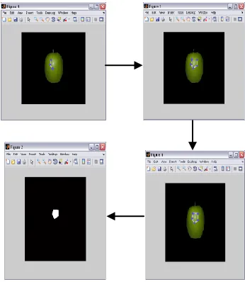
[image:4.612.355.544.70.532.2]From the previous results shown in Fig.7, we use the user interactive module to solve the problem in the reconstructed surface of apple. . In this module, the user identifies the problem area as a polygona. Then the mask of the selected region is automatically created (Fig.8). Using information from the neighboring regions, the depth of the selected region is corrected. (Fig. 9).
Fig 8. Selecting the problem region.
Fig 9. Reconstructed surface of apple after applying user interactive module.
4.7
Comparative study
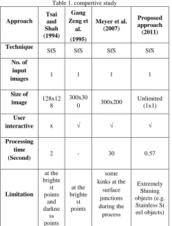
[image:4.612.85.258.473.672.2]Table 1. compertive study
Approach
Tsai and Shah (1994)
Gang Zeng et
al. (1995)
Meyer et al. (2007)
Proposed approach (2011) Technique
SfS SfS SfS SfS
No. of input
images 1 1 1 1 Size of
image 128x12
8
300x30
0 300x200
Unlimited (1x1)
User
interactive x √ √ √
Processing time
(Second) 2 - 30 0.57
Limitation
at the brighte st points
and darkne
ss points
at the brighte st points
some kinks at the
surface junctions during the
process
Extremely Shining objects (e.g. Stainless St eel objects)
5. CONCLUSION
In this paper, we have presented a novel approach for reconstructing 3D surfaces of object from a single image through the use of shading information. The aim is to retain the robustness and flexibility of using a user interactive model for constructing 3D surfaces from a single image. Furthermore the proposed approach supports computer graphics applications, such as medical applications, and recognition applications.
6. REFERENCES
[1] R. Zhang, P. S. Tsai, J.E. Cryer, and M. Shah, Shape from Shading: A Survey. IEEE Transactions on Pattern Analysis and Machine Intelligence, no. 21, vol. 8, 1999, pp. 690– 706.
[2] J.D. Durou, M. Falcone, and M. Sagona, A Survey of Numerical Methods for Shape from Shading. Rapport de Recherche 2004-2-R, Institut de Recherche en Informatique de Toulouse, Toulouse, France, 2004.
[3] A. Gültekin, and M. Gökmen, Adaptive Shape from Shading. Elektrik, no. 6, vol. 2, 1998, pp. 61 – 73.
[4] A. Meyer, H.M. Briceno, and S. Bouakaz, User-guided Shape from Shading to Reconstruct Fine Details from a Single Photograph. 8th Asian Conference on Computer Vision, Tokyo, Japan. Identifiant LIRIS, 2007.
[5] J.D Durou, L. Mascarilla, and D. Piau, Non-Visible Deformations. In: 9th International Conference on Image Analysis and Processing - ICIAP’97, Florence, Italie, 1997. [6] E. Prados, and O. Faugeras, Shape from shading: a well-posed problem ? In: Proceedings of the IEEE Conference on Computer Vision and Pattern Recognition (CVPR’05), San Diego, California, vol. II, IEEE, 2005, pp. 870–877. [7] G. Zeng, Y. Matsushita, L. Quan, and H. Y. Shum,
Interactive Shape from Shading. In: Proceedings of the IEEE Conference on Computer Vision and Pattern Recognition, vol. I, San Diego, California, USA, 2005, pp. 343–350.
[8] A. Patel and W.A.P. Smith, Shape-from-shading driven 3D Morphable Models for Illumination Insensitive Face Recognition. In Proc. BMVC, 2009.
[9] W. M. Sheta, M. F. Mahmoud, E. H. Atta, Evolutionary Computation Approach for Shape from Shading. In: IJICIS, vol. 5, no. 1, 2005.
[10]I. Kemelmacher-Shlizerman, R. Basri, 3D Face Reconstruction from a Single Image Using a Single Reference Face Shape. In: Proceedings of IEEE Transactions on Pattern Analysis and Machine Intelligence vol. 33, 2011.
[11]S. R. Buss, 3-D computer graphics: a mathematical introduction with OpenGL, 2003.