A Specific-domain Design Tool for FPGA-based Image
and Video Processing System
Noureddine ZHAR
Lab. SIR - Mohammadia School of Engineers
Rabat, Morocco
Mohamed AIT ALI
Lab. SIR - Mohammadia School of Engineers
Rabat, Morocco
Amine RAJI
LabSTICC–ENSTA-Bretagne Brest, France
Mohsine ELEULDJ
National School of Applied Sciences
Oujda, Morocco
ABSTRACT
The complexity of image processing algorithms using mathematical calculations grows from the nature of the image to be processed and the desired result. A hardware implementation of these algorithms for the needs of real-time and embedded systems improves performances. In this paper we present some existing approaches used for hardware systems modeling. We propose a new graphical tool for designing image and video processing embedded systems called VIP DESIGN (Video and Image Processing Design). The novelty of our approach is that we bypass the shortcomings of existing languages by providing a high level of abstraction through two kinds of diagrams: structural diagram and filter edition diagram. It also allows formal verification and automatic code generation for ASIC and FPGA implementation.
General Terms
FPGA, Image processing, embedded system, real-time.
Keywords
VIP DESIGN, Structural diagram, filter editing diagram
1.
INTRODUCTION
The growth of images resolution, the nature and diversity of associated applications require implementation of complex image processing algorithms. Sequential implementation of these algorithms has quickly shown its limitations, particularly for real-time applications, due to the important quantity of data to be processed and the strong temporal constraints that characterize such systems [1]. A hardware implementation, which allowsparallelizing some parts of the processing and reducing the execution time and consumption of resources, seems to be the best solution to meet time and budget requirements.
FPGA (Field Programmable Gate Arrays) is the suited platform to achieve this goal[2]. The implementation of image processing applications on FPGAs differs significantly from the one used on platforms using conventional processors and a large space of memory. For FPGAs, we have to define the algorithm itself and the hardware architecture on which it will be implemented.
In this context, the development and implementation of image processing algorithms on FPGAs, using descriptive language, is an arduous, difficult and costly task in terms of development time, readability and maintainability.
The development of a graphical language for designing image processing algorithms would reduce development effort, improve the clarity of the solution and serve as a reliable communication tool. It will provide an opportunity to represent graphically the solution which will be automatically translated into a low-level hardware describing language. This paper presents a graphical language for image and video processing for embedded systems design called VIP DESIGN. We developed this tool to allow design at high level of abstraction while providing an opportunity to detail designed system behavior and automatic generation of code that can be synthesized for hardware implementation needs. The time constraints paradigms integrated in VIP DESIGN make it appropriate for modeling real-time [1] applications.
2.
RELATED WORKS
In this section, we will discuss some related works and tools and present their advantages and inconveniences.
2.1.
Handel-C
Handel-C [3] is a low-level programming language to design hardware component such as FPGAs. It is a C-like language with extensions to control the hardware aspects of mixed systems. It integrates features to parallelize processes and can be compiled to multiple design languages (VHDL, EDIF) and then synthesized to the target hardware platform. Handel-C allows the designer to break away from the physical structure of the system and focus on its behavior. Closed to the C language, widely used, this language is easily mastered and does not require a great effort for its handling which greatly reduces the design and development time of hardware systems. However, this gain in terms of time and simplicity is combined with losses in performance due to the automatic translation from Handel-C to VHDL or EDIF. In this case, the produced code requires a manual refinement to optimize the solution implementation on hardware.
2.2.
UML profiles for embedded systems
designs
UML profile defines a "Domain Specific Modeling Language" without contradicting the semantics of UML by:
adding concepts relating to a particular field, changing the representation of these concepts, defining constraints applied to the associations
adding constraints on the use of certain concepts or not depending on the context and the identification of semantic variation points.
SysML [4] is a UML profile for modeling systems. It incorporates additional concepts adapted to the design of embedded and real-time systems. These concepts are sometimes inadequate to the spirit of UML and suitable to the representation of hardware systems. However, they remain inapplicable in the case of a complete automated development flow [5].
Other works have attempted to use the standard notation of UML, particularly those of the activity, composition and deployment diagram, in order to model the behavior, composition and functional block for hardware systems [5]. The model thus produced can be subject to transformation and generation rules to obtain a descriptive code.
This language does not provide sufficient flexibility to define other specific concepts such as data types (pixel, raw,…).
2.3.
VERTIPH
VERTIPH [6] (Visual Environment for Real-Time Image Processing in Hardware) is a design environment for image processing applications for real-time systems.
It offers three views covering different aspects of an image processing system: An architectural view, a computational view and a scheduling and resource sharing view. This language attempts to meet the specificity of image processing applications to be implemented on FPGAs in terms of data types, reuse of primitive functions specific to this area and the graphical representation of competitive and sequential execution of different functional blocks of the designed system. However, although it is considered as a high-level design environment which don’t require hardware knowledge, this tool requires a perfect mastery of resource sharing concepts and a good ability to handle and define data types at a very low-level of abstraction. This specific knowledge makes the use of this tool inaccessible to a large developer community unaccustomed to such concepts. VERTIPH doesn’t integrate verification and validation of the designed model before the implementation phase considered expensive in terms of time and cost.
3.
VIP DESIGN
In order to dispel difficulties associated with the use of textual languages and provide answers to the limits of visual languages described in the previous section, we propose a new graphical language called VIP DESIGN. This section presents our approach to develop this tooland both of its structural and filter edition diagrams.
3.1.
Approach
VIP DESIGN, a graphical language for image and video processing embedded systems design, proposes an approach based on a graphical representation of structural and behavioral aspects of designed system while abstracting details about the physical architecture.
This is possible through two types of diagrams. Embedded and real-time image processing system has input interfaces for data acquisition and an output interface to deliver its returned results.
The processing can be described as a sequence of several sequential or competitive filters which communicate through channels or shared memory.
The first diagram we use is called Structural Diagram. Its purpose is to model the structural description of the system through a hierarchical composition of all necessary functions.
A second diagram can describe each basic element of this hierarchical structure. This diagram called Filter Editing Diagram details the processing functions through a description of elementary operations and their scheduling.
3.2.
Structural Diagram
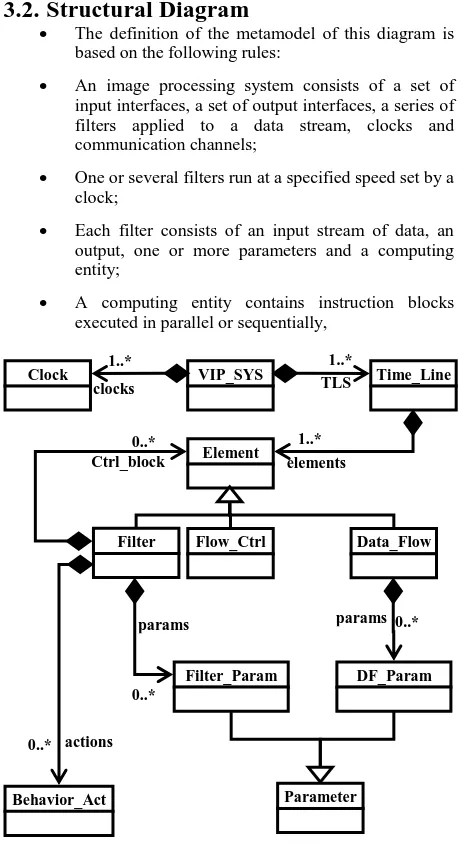
The definition of the metamodel of this diagram is based on the following rules:
An image processing system consists of a set of input interfaces, a set of output interfaces, a series of filters applied to a data stream, clocks and communication channels;
One or several filters run at a specified speed set by a clock;
Each filter consists of an input stream of data, an output, one or more parameters and a computing entity;
[image:2.595.314.545.120.548.2] A computing entity contains instruction blocks executed in parallel or sequentially,
Fig. 1 : Partial view of VIP DESIGN metamodel
3.3.
Filter Diagram
The behavior of an embedded and real-time image processing system can be described by defining three basic aspects:
An accurate expression of structural (conditional branches, loops), arithmetic and/or logic operations executed by the system;
Scheduling of these operations;
Defining rules to manage competitive access to shared resources;
3.3.1.
Expression of filter operation:
A clear expression of the system operations requires an action language using a concrete syntax with a sufficient level of accuracy to enable an unambiguous code generation. To meet this need, we used the package "Action" of the intermediate modeling language COCODEL [7]. It includes all the basic actions defined in [8] and [9]required to design embedded
VIP_SYS
Clock
Time_Line
Element
Filter
Flow_Ctrl
Data_Flow
Parameter
Behavior_Act
Filter_Param
DF_Param
1..*
clocks
1..* TLS
1..* elements 0..*
Ctrl_block
0..* actions
0..*
systems. This package allows describing the body of all actions, expressions or operations of the computing entity.
Fig. 2: Package “ACTION”
3.3.2.
Scheduling
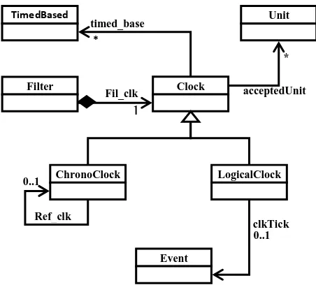
The increasing complexity of algorithms and the large volume of data handled in image processing present a serious challenge which requires a considerable computation time to perform this complex process. Parallelizing tasks represents an effective solution to obtain more efficient in execution speed. This parallelism cannot be designed without an associated model of time. Therefore, VIP DESIGN language manages different real-time constraints related to image processing via a TIME package facilitating the addition of temporal information to model elements. This package allows manipulating the values of temporal parameters and markup language elements with temporal information later used by tools for simulation, performance analysis, verification, validation and analysis of schedulability. In fact the components of our language are related to time through one or more clocks which give the possibility to use multiple temporal repositories in the same VIP DESIGN model and divide time into a succession of discrete instants for modeling parallel processing, concurrency, and support the design of distributed and multi-clocks electronic systems.
Fig.3: Partial view from VIP DESIGN time model
3.4.
Formal analysis framework
We integrated real-time constraints modeling related to image processing in the TIME package of our tool. To address these constraints, formal techniques have gained much attention since they provide fundamental techniques to analyze, validate and transformsystems in a provably sound way. For that reason, we provide a verification framework to ensure the respect of time constraints at model level.
Our verification framework is based on an existing model checking, named CADP-toolbox [10]. We opted for model checking rather than theorem proving because of possibility to automatically check behavioral and timed properties.
The question that we are answering is: “once we model our image processing algorithm into the FPGA, how can we check the respect of behavioral and timed requirements before going any further and generating the implementation code?”
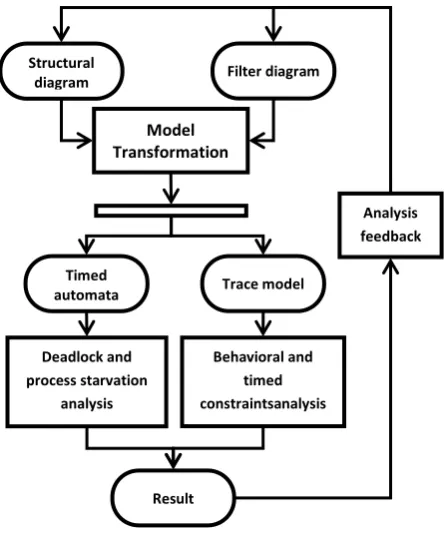
To answer this question, we integrated a formal verification framework into our design tool. This framework takes as input both the structural and the filter diagrams, and produces as a result a formal model expressed in the form of a set of timed automata. We defined an ad-hoc domain-specified transformation language in terms of Ecore metamodel and define a Model-to-Model transformation chain. From the structural diagram, our verification framework generates a timed automaton that represents the flow of data through computing entities to check the absence of deadlocks and process starvations. From Filter Diagram we generate a timed automaton to check the respect of behavioral properties according to structural and arithmetic and/or logic operations. Model transformations used to generate formal artifacts from Structural and Filter diagrams generate a trace model for each transformation. The trace model is used later to trace back verification result in order to give a diagnosis support for the designer. Figure 4 shows an overview of the analysis process of our verification framework.
TimedBased Unit
Clock
Filter
ChronoClock
LogicalClock
Event
* timed_base
*
acceptedUnit
1
Fil_clk
0..1 clkTick 0..1
Ref_clk Behavior_Action
Loop
IfElse
Assignement
Action Block
Event
SendSigEvent
CallOpEvent
SendSig
CallOp
Communication
ifBlk 1
elseBlk 1
create 0..1
[image:3.595.56.281.109.357.2]Fig. 4 : Formal analysis process overview
4.
APPLICATION: DETECTION OF
AIMING DIRECTIONS IN A SHOOTING
SIMULATOR
This example concerns the implementation of a tracking algorithm used in the development of an indoor small arms shooting simulator. This simulator implements multi-firing weapons. Each weapon has an infrared laser diode which diffuses an invisible beam materializing the line of sight of each shooter on the screen. An infrared camera delivers a video stream to which we apply a complex image processing algorithm to determine, with a sufficient precision and in real time, the aiming direction of each shooter.
4.1.
Initial solution
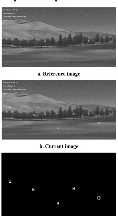
[image:4.595.324.534.69.364.2]The processing algorithm to be applied to the video stream is entirely deployed on a computer dedicated to managing the whole simulation process. This algorithm can be decomposed into two main phases. In the initialization phase we save a grayscale reference image of the scene displayed on the screen. During the second phase of processing each new image is converted to grayscale and then subtracted from the reference image before applying a threshold filter. The residual noise is reduced through a smoothing filter. This sequence of filters isolates highlight spots. At this stage, we proceed to the detection of blobs to determine their sizes and coordinates on the screen. All detected spots are injected to a tracking algorithm to assign each spot to its corresponding shooter.
Fig. 5 : Description of the initial solution
The whole of this process was implemented on a computer using a conventional processor (intel Pentium IV, 2,4 GHz). Consequently, the system performances decrease significantly. indeed, we were forced to limit the video rate at 10 frames / second instead of a stream of 24 frames / second required for a proper analysis of the stability of the weapon before, during and after the shot as well as to reduce the image resolution from 1028px × 768px to 600px × 400px, which amplifies errors in calculating the coordinates of the points aimed at by shooters.
4.2.
Adopted solution
To find a solution to the shortcomings of the original architecture described, we adopt a hardware implementation to parallelize some of the processing and comply with the time constraints required by this simulator.
The figure below describes the new reached solution. We deploy a large part of the processing on a FPGA. After saving the reference image, each new image will be subject to a parallelized processing to extract a list of spots (blob List). Conversion operations to grayscale and subtraction have repetitive blocks which can be parallelized. The designed system will provide in output a list containing the coordinates and sizes of detected spots. This list will be injected into the tracking algorithm deployed on the computer dedicated to manage simulation.
Co
mp
ute
r
L
o
o
p
Save reference image
Subtraction
Lens distortion
Threshold
Smoothing
Blobs extraction
Blobs tracking Structural
diagram Filter diagram
Model Transformation
Timed
automata Trace model
Result Deadlock and process starvation
analysis
Behavioral and timed constraintsanalysis
Fig. 6 : Description of the adopted solution
4.3.
Hardware implementation
To implement the solution described above, we define a system (SYSTEM). This system has an input stream Image and a Boolean one called first injected into a conditional block to redirect to the initialization phase or to the processing one. The system provides a list of spots (Blobs list) in output. This processing will run while the video stream is available in input. We apply a succession of filters pipelined to perform a parallel processing to improve the execution time.
The data stream split to five FIFO is injected into a pipelined processing with five filters. Each stage of processing can be parallelized internally while the computational tasks are independent. Diagrams are produced using a graphical tools created with eclipse GMF [11]. We use ACCELEO [12] to define transformation and generation rules to produce Handel-C code.
4.4.
Results
[image:5.595.315.541.78.297.2]This hardware implementation allowed us to circumvent the limitations of a sequential implementation. We were able to meet the requirements of our simulator by improving the image stream at 23 images / second using a resolution of 1028px × 768px. Using VIP DESIGN allows us to minimize development effort and to reduce prototyping time. The following tables summarize the obtained results.
Fig.7 : Solution designed with VIP DESIGN
a. Reference image
b. Current image
c. result after blob detection filter
Fig.8 : Result of image processing SYSTEM
While(frame)
rgb2gray
PAR
subtract
Lens_distor
smoothing
Blob_extract Save frame
Image :streamin
BLOBS :blobList
Comp
u
ter
FPG
A
Loo
p
Save reference image
Subtraction
Lens distortion
Threshold
Smoothing
Blobs extraction
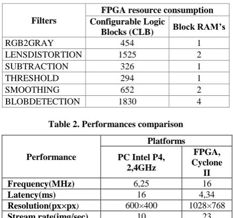
[image:5.595.328.529.315.681.2]Table 1. FPGA resource consumptions by filters
Filters
FPGA resource consumption Configurable Logic
Blocks (CLB) Block RAM’s
RGB2GRAY 454 1
LENSDISTORTION 1525 2
SUBTRACTION 326 1
THRESHOLD 294 1
SMOOTHING 652 2
BLOBDETECTION 1830 4
Table 2. Performances comparison
Performance
Platforms
PC Intel P4, 2,4GHz
FPGA, Cyclone
II Frequency(MHz) 6,25 16
Latency(ms) 16 4,34
Resolution(px×px) 600×400 1028×768
Stream rate(img/sec) 10 23
Developmenteffort 50h
3254 lines of code 8h
Obtained results confirm the suitability of hardware implementation for image processing algorithms running under severe time constraints. Thus, we could significantly improve execution time to go from16msto 4,34ms. By using higher resolution and frame rate, we decreased errors when calculating shooter aiming directions. Being a visual tool, placing designer at a high level of abstraction and promoting the concept of reuse, VIP DESIGN reduces development time and improves the clarity of the solution. Handel-C code generated from the model created with VIPDESIGN is easy to understand by software developers because of its similarity with high level programming languages. However, the final solution implemented on FPGA doesn’t reach a satisfactory level of optimization, as shown in table I, particularly in terms of occupation rate.
5.
CONCLUSION
Hardware implementation of image processing algorithms is an adequate solution to improve execution time and to optimize resource consumption. Several programming languages such as VHDL and Handel-C, are used to describe hardware systems. However, the increasing complexity and the need to reduce development time motivate the rise of graphical design tools to raise the abstraction level and overcome difficulties related to hardware concepts. We proposed VIP DESIGN, a new graphical language for embedded and real-time image and video processing systems design. The approach proposed by VIP DESIGN is based on the description of the system through the scheduling of several sequential or competitive filters communicating through channels and running at a speed set by the same or different clocks. This is possible by using two kinds of diagram that allow the designer to define the functional structure and the internal behavior of the system. The structural diagram describes the functional hierarchy of the system. Filter edition diagram is used to describe the internal behavior of each filter using an action language. Time constraints are expressed by integrating clauses adapted to real-time system design. For the verification of these constraints we integrated a formal verification framework that generates formal models from our graphical diagrams. Generated code is puttedin the input of the CADP-Toolbox for model checking behavioral and timed properties. We illustrate, through a real case of study, that the
use of VIP DESIGN to design a real-time system allows a graphical representation to increase the visibility of the designed system and a rapid prototyping without hardware knowledge.
However, VIP DESIGN does not cover the entire design and development flow. To this end, the Handel-C code generated automatically from the produced model must be submitted to a verification and simulation process before its implementation. Actually, we use a tool provided by Celoxica [13] to simulate and compile generated code. Development of an owner simulator will be subject to future works.
6.
REFERENCES
[1] Venkateshwar,R., Patil,P., Naveen, A., Muthukumar,V., «Implementation and Evaluation of Image Processing Algorithms on Reconfigurable Architecture using C-based Hardware Descriptive Language,» International Journal of Theoretical and Applied Computer Sciences, 2006.
[2] W. J. MacLean, «An Evaluation of the Suitability of FPGAs for Embedded Vision Systems,» chez Computer vision and pattern recognition, San Diego, CA, 2005.
[3] RG, Handel-C Language Reference Manual, Celoxica Limited, 2005.
[4] S. Partners, "SysML Specification v. 1.0a," 2005. [Online]. Available: http://www.sysml.org.
[5] Tim Schattkowsky, Jan Hendrik Hausmann, Gregor Engels, «Using UML Activities for System-On-Chip design and synthesis,» Springer, 2006.
[6] C.T.Johnston, D.G.Bailey, P.Lyons, «A Visual Environment for Real-Time Image Processing in Hardware (VERTIPH),» EURASIP Journal on Embedded Systems, p. 1–8, 2006.
[7] M.AIT ALI, M.ELEULDJ, «An intermediate modelisation Language for embedded system developemnt chain COCODEL : Un Langage intermédiaire de modélisation pour une chaine de développement des systèmes embarqués COCODEL,» chez JODIC'2012, Rabat, 2012.
[8] E. Planas, J. Cabot et a. C. Gómez, «Verifying Action Semantics Specifications in UML,» Springer-Verlag Berlin Heidelberg, vol. CAiSE 2009, n° %1LNCS 5565, pp. 125-140, 2009.
[9] OMG, OMG Unified Modeling Language Specifications (Action Semantics), OMG, 2009.
[10] J.-C. Fernandez, G. Hubert , A. Kerbrat, L. Mounier , R. Mateescu et M. Sighireanu, «CADP : A Protocol Validation and Verification Toolbox,» chez CAV ’96 : Proceedings of the 8th International Confe- rence on Computer Aided Verification, London, UK, 2006.
[11] E. Foundation, «Graphical Modeling Framework,» The
Eclipse Foundation, [En ligne]. Available:
http://www.eclipse.org/modeling/gmp/.
[12] E. Foundation, «Acceleo,» Eclipse Foundation, [En ligne]. Available: http://www.eclipse.org/acceleo/.
[13] RG, Pixel Streams manual, Celoxica, 2005.
[14] Charest, L., Aboulhamid, E.M., «A VHDL/SystemC Comparison in Handling Design Reuse,» 2008.
[15] OMG, OMG Unified Modeling LanguageTM (OMG UML), Superstructure, Version 2.3, 2010.
[16] OMG, "Meta Object Facility (MOF) 2.0