International Journal of Emerging Technology and Advanced Engineering
Website: www.ijetae.com (ISSN 2250-2459, Volume 2, Issue 7, July 2012)
438
State Of Art Review - Base Isolation Systems For
Structures
S.J.Patil
1, G.R.Reddy
21Heavy Water Board, Mumbai, India . 2Bhabha Atomic Research Centre, Mumbai, India .
1[email protected] 2[email protected]
Abstract — This paper presents an overview of the present state of base isolation techniques with special emphasis and a brief on other techniques developed world over for mitigating earthquake forces on the structures. The dynamic analysis procedure for isolated structures is briefly explained. The provisions of FEMA 450 for base isolated structures are highlighted. The effects of base isolation on structures located on soft soils and near active faults are given in brief. Simple case study on natural base isolation using naturally available soils is presented. Also, the future areas of research are indicated.
Keywords—State of Art, base isolation, modulus reduction, FEMA 450, isolated footing, raft footing.
I. INTRODUCTION
The structures constructed with good techniques and machines in the recent past have fallen prey to earthquakes leading to enormous loss of life and property and untold sufferings to the survivors of the earthquake hit area, which has compelled the engineers and scientists to think of innovative techniques and methods to save the buildings and structures from the destructive forces of earthquake. The earthquakes in the recent past have provided enough evidence of performance of different type of structures under different earthquake conditions and at different foundation conditions as a food for thought to the engineers and scientists. This has given birth to different type of techniques to save the structures from the earthquakes.
Base isolation concept was coined by engineers and scientists as early as in the year 1923 and thereafter different methods of isolating the buildings and structures from earthquake forces have been developed world over. Countries like US, New Zealand, Japan, China and European countries have adopted these techniques as their normal routine for many public buildings and residential buildings as well. Hundreds of buildings are being built every year with base isolation technique in these countries.
This paper describes the development of base isolation techniques and other techniques developed around the world.
As of now, in India, the use of base isolation techniques in public or residential buildings and structures is in its inception and except few buildings like hospital building at Bhuj, experimental building at IIT, Guwahati, the general structures are built without base isolation techniques. National level guidelines and codes are not available presently for the reference of engineers and builders. Engineers and scientists have to accelerate the pace of their research work in the direction of developing and constructing base isolated structures and come out with solutions which are simple in design, easy to construct and cost effective as well.
Many significant advantages can be drawn from buildings provided with seismic isolation. The isolated buildings will be safe even in strong earthquakes. The response of an isolated structure can be ½ to 1/8 of the
0.0 0.5 1.0 1.5 2.0 2.5
0.0 0.2 0.4 0.6 0.8 1.0 1.2
Fig.5 Regions of response control and Base Isolation
Direction of response control along increse in damping
Region of Base isolation
Envelop spectra with o.2 g ZPA 1% 2% 3% 4% 5% 7% 10% R es po ns e A cc el er at io n in g u ni ts Time (Sec)
Region in which base isolated structure lies
International Journal of Emerging Technology and Advanced Engineering
Website: www.ijetae.com (ISSN 2250-2459, Volume 2, Issue 7, July 2012)
439
traditional structure. Since the super structure will be subjected to lesser earthquake forces, the cost of isolated structure compared with the cost of traditional structure for the same earthquake conditions will be cheaper. The seismic isolation can be provided to new as well as existing structures. The buildings with provision of isolators can be planned as regular or irregular in their plan or elevations. [1].Researchers are also working on techniques like tuned mass dampers, dampers using shape memory alloys etc. Tuned mass dampers are additional mass on the structure provided in such way that the oscillations of the structure are reduced to the considerable extent. The mass may be a mass of a solid or a mass of a liquid. Dampers using shape memory alloys are being tried as remedy to earthquake forces. In this system, super elastic properties of the alloy is utilized and there by consuming the energy in deformation at the same time the structure is put back to its original shape after the earthquake.
II. BASE ISOLATION TECHNIQUES
In traditional seismic design approach, strength of the structure is suitably adjusted to resist the earthquake forces. In base isolation technique approach, the structure is essentially decoupled from earthquake ground motions by providing separate isolation devices between the base of the structure and its foundation. The main purpose of the base isolation device is to attenuate the horizontal
acceleration transmitted to the superstructure. All the base isolation systems have certain features in common. They have flexibility and energy absorbing capacity. The main concept of base isolation is to shift the fundamental period of the structure out of the range of dominant earthquake energy frequencies and increasing the energy absorbing capability. The concept is explained in Fig. 1.
Presently base isolation techniques are mainly categorized into three types viz. 1) Passive base isolation techniques 2) Hybrid isolation with semi-active devices 3) Hybrid base isolation with passive energy dissipaters. These different techniques are discussed in short below –
III. PASSIVE BASE ISOLATION TECHNIQUES
A. Mud layer below the structure
Frank Lloyed Wright was the first person who implemented the idea of base isolation technique for isolating Imperial Hotel structure in Tokyo, by providing closely spaced short length piles in 8 feet thick soil layer underlain by a thickness of mud layer over hard strata. The building survived an earthquake in 1923. [2], [3]
B. Flexible first storey
[image:2.612.126.536.485.654.2]The flexible first storey concept was first proposed by Martel in 1929 and was further studied by Green in 1935 and Jecobson in 1938 thereby reduce the loading on upper storey members. However, further studies by Chopra et. al.
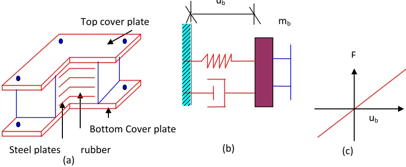
Fig. 2. Laminated rubber bearing system - a) Sectional details b) Schematic diagram c) Force deformation behavior
u
bF
Top cover plate
Steel plates
rubber
Bottom Cover plate
(a)
(c)
(b)
m
bInternational Journal of Emerging Technology and Advanced Engineering
Website: www.ijetae.com (ISSN 2250-2459, Volume 2, Issue 7, July 2012)
440
with the aid of computers showed that the concept is impractical [3]. Also the recent earthquakes at Bhuj in India and Kobe in Japan have revealed that most of the buildings with soft storey have suffered extensive damage.C. Roller bearings in foundations
Roller bearing systems proposed for isolation of the structures were having serious drawback as the rollers were having to and fro motion in particular direction and earthquake has three directions motion due to which earthquake forces could not be isolated effectively. Also the main problem was that the device needed maintenance for keeping in good operation throughout its working life period. The system was further modified with ball bearing system.
D. Rubber layer as foundation support
School building in Skopje, Yugoslavia constructed on rubber foundations in 1969 [3], used to bounce and rock forward and backward during earthquake due to uniform stiffness of rubber in all directions. Also the rubber foundation bulged under the weight of the building.
E. Laminated rubber bearing system
Laminated rubber bearings (LRB) (ref. Fig. 2), which are made of thin layers of steel plates and rubber built in layers one over the other, have horizontal flexibility, high vertical stiffness and they can be characterized by natural frequency and damping constant.
The main advantages [1] of rubber bearing system are - 1. Effective isolation is achieved. It will decrease the structural response to 1/2 -1/8 of the traditional structural
response.
2. Stable character of isolators over a long working life. 3. Recovery of the displacement after earthquakes. 4. Vertical tension capacity is good.
5. Isolators are insensitive for foundation settlement, which are generally small in magnitude. It could adjust the structure force by deformation of rubber bearings when foundation settlement of building happens before or after earthquakes.
6. Decreasing the temperature stress in structures by free horizontal deformation of bearings during large change of temperature around the structure.
F. New Zealand bearing system
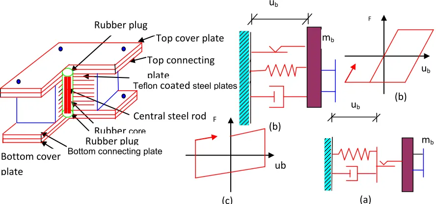
The system (ref. Fig. 3), invented in NewZealand in the year 1975, [4] is improved version of laminated rubber bearing wherein a centrally located lead core is introduced, which has energy dissipating capacity. The presence of lead core reduces displacement of the isolator and isolator essentially works as hysteretic damper device. The device has been extensively used in New Zealand, Japan and USA. Buildings isolated with these devices performed well during the 1994 North ridge earthquake and 1995 Kobe earthquake.
G. Resilient – friction base isolation system
Resilient – Friction Base Isolation (R-FBI) system (ref. Fig. 4) proposed by Mostaghel and Khodaverdian consists of concentric layers of Teflon coated plates which will have
F
u
b(c)
m
bu
b(b)
Steel plates
Top cover plate
rubber
(a)
Lead core
[image:3.612.85.515.526.664.2]Bottom cover
plate
International Journal of Emerging Technology and Advanced Engineering
Website: www.ijetae.com (ISSN 2250-2459, Volume 2, Issue 7, July 2012)
441
sliding resistance and a central core of rubber which will have beneficial effect of resilience of a rubber.H. Electric de-France system
Electric De-France (EDF) (ref. Fig. 5) system is friction type base isolation system developed under the auspices of Electric de France in the year 1970. The system is standardized for Nuclear power plants in the region of high seismicity. The system consists of laminated Neoprene pad topped by a lead bronze plate, which is in frictional contact with steel plate anchored to the base raft of the structure. Therefore its cross section is similar to the LRB system. The neoprene pad has very low displacement capacity (5 cm approx.) and when this capacity is exceeded, the sliding element provides the needed movement. The system does not include any restoring device and hence permanent displacement could occur. The system has been implemented in nuclear power plant at Koeberg in South Africa.
I. Sliding resilient- friction system
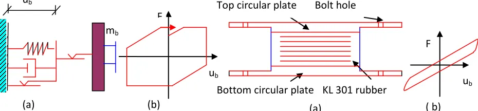
The design of sliding resilient- friction base isolator (refer fig. 6) was proposed by Su et. al. This isolator is combination of good features of EDF and R-FBI systems.
The upper surface of the R-FBI system is replaced with friction plates. As a result the structure can slide on its foundation in a manner similar to that of the EDF base isolator system. For a low level of seismic excitation, the system behaves as an R-FBI system. The sliding in the top plates occurs only during high level of ground acceleration, which provides additional safety against unexpected severe ground motion.
J. High damping rubber bearing
A blend of high damping rubber is used in these bearings (ref. Fig. 7). The compound, a high damping elastomer, is called KL301 and is manufactured by the Bridgestone Corporation Limited, Japan. KL301 has a shear modulus of about 4300 kPa at very small strains, which decreases to 650 kPa at 50% strain, to 430 kPa at 100% strain and 340 kPa at 150% strain. The typical bearing made of this rubber, consists of 20 layers of 2.2 mm thick rubber at 176 mm dia, nineteen 1mm steel shims, and 12 mm top and bottom plates. The design axial pressure is 3.23 MPa. The bearings were designed with flange type end plates to provide bolted structure and foundation connection.
K. Pure friction system
ub
F(c)
u
bm
b(b)
Rubber plug
Top cover plate
Top connecting
plate
Teflon
coated
steel platesCentral steel rod
Rubber
coreRubber plug
Bottom cover
plate
[image:4.612.92.536.431.639.2]Bottom connecting plate
Fig. 4.Resilient – friction base isolation system a) Sectional details b) Schematic
diagram c) Force deformation behavior
u
b F(b)
m
bu
b(a)
International Journal of Emerging Technology and Advanced Engineering
Website: www.ijetae.com (ISSN 2250-2459, Volume 2, Issue 7, July 2012)
442
A pure friction type base isolator consists of developing frictional force by providing a sand layer or rollers at the base, which will dissipate the energy of earthquake force. The system is developed in China for low-rise structures. The system is useful for wide range of frequency input.The main advantage of this isolation device is that it is very cheap. The main problem with the system is that it is unable to recover the displacement after earthquakes and sand layer is very sensitive for foundation settlement. [1].
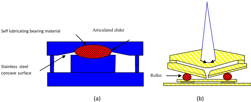
L. Friction pendulum system
Friction pendulum system (ref. Fig. 8) uses geometry and gravity to achieve the desired seismic isolation. It is based on well-known engineering principles of pendulum motion. The structure supported by the FPS responds to the earthquake motions with small pendulum motions. The friction damping absorbs the earthquake energy. There are variety of friction pendulum system developed by various researchers such as, variable frequency pendulum isolators by pranesh & sinha, 2000, variable curvature pendulum systems by Tsai et al, 2003, sliding concave foundation by Hamidi et al., 2003, double concave friction pendulum system by Fenz and Constantinou, 2006, Triple friction pendulum bearing, Fenz and Constantinou 2008. Friction pendulum system is very efficient and cost effective seismic protection device, which simply alter the force response characteristics of the structure at base isolation level.
M. Spring type systems [4]
Elastomeric and sliding isolation systems are effective in isolating the structure from horizontal forces. When three dimensional isolation is required, spring type systems have been used. The spring type system under the brand
name of GERB was developed with large helical steel springs having flexibility both in horizontal and vertical direction. The vertical frequency of the system was 3 - 5 times the horizontal frequency. The steel springs were used with GERB visco damper.
The system has been used in two steel framed houses in santa Monica, California. These houses were strongly affected by the 1994 Northridge earthquake. The response of these buildings was monitored and it was not effective in reducing the accelerations in these buildings due to rocking motion.
N. Sleeved pile isolation system [4]
Where foundation soil is very soft up to large depths and provision of pile foundation is necessary, sleeved pile isolation system is useful from earthquake considerations. The system consists of providing a casing around the pile and a gap is maintained between the pile and the casing to accommodate the sway of the pile under earthquake load. The pile is passed through the soft soil and is supported and anchored in the rock below.
This system was implemented in the Union house in Auckland, New Zealand in the year 1983. The building is 12 storeys tall and is supported on piles through soft soil for depth of 10m enclosed in steel casing. The period of the building on the sleeved pile system is 4 seconds.
O. Rocking systems [4]
Tall slender structures, having heavy mass at the top, will invariably develop overturning moments which will lead to development of tensions in the foundations. It is extremely difficult to provide tension capacity in the foundations when foundations are in weak soil and providing anchors is a costly affair. As a remedy to this
( b)
u
bF
(a)
KL 301 rubber
Bottom circular plate
[image:5.612.80.545.553.661.2]Top circular plate
Bolt hole
Fig. 7. High damping rubber bearing (a) Sectional details b) Force deformation behavior
Fig. 6. Sliding resilient friction system (a) Schematic diagram (b) Force deformation behavior
(b)
u
bF
(a)
u
bInternational Journal of Emerging Technology and Advanced Engineering
Website: www.ijetae.com (ISSN 2250-2459, Volume 2, Issue 7, July 2012)
443
problem, it is possible to allow lifting of columns or piers from the foundation. This type of partial isolation will reduce the earthquake loads throughout the structure.This concept was implemented in a railway bridge on south Rangitikei river in New Zealand in the year 1972. It has 69m long pier, which has been designed to lift under the earthquake load. Two large energy dissipating devices that are based on the elastic-plastic torsion of mild steel bars have been provided inside each pier. The method is not used again probably due to complexities involved in analysis and design of the system.
P. Base isolation using Geo- Synthetic materials [5] M.K. Yegian and U. Kadakal have developed a technique of isolating the base of the structures using geo-synthetic material. They have used high strength, non woven geotextaile placed over an ultra high molecular weight polyethelene (UHMWPE) liner. These two materials have a static friction co-efficient of 0.1 and a dynamic friction coefficient of 0.07. Thus a geo-synthetic material placed underneath a foundation of a structure and over a liner will allow the dissipation of earthquake energy in sliding friction. They suggested that the sliding friction between the two materials should be in the range of 0.05 to
0.15. The authors have suggested arrangements as shown in fig 9 except the energy dissipating devices.
Q. BS cushion [6]
In 1999 a new kind of base isolator called BS cushion was invented (Chinese Patent Number ZL99202381.5) in Hangzhou, China. It is Treated Asphalt-Fiber Seismic Base Isolation Cushion”. The advantage of this kind of isolator is its low cost and safety while its isolation effect is moderate.
The invention of BS cushion reminds laminated steel-plate rubber bearing. Fiber and treated asphalt in BS cushion play similar role as of steel-plate and rubber in laminated rubber bearing respectively. Before 2001 two 7-storey masonry-concrete residential buildings isolated with BS cushion were built in Hangzhou, China. One is isolated by replacing some depth of base soil under mattress foundation with alternative setting of 4 layers of BS cushion and 4 layers of sand. The fundamental period of this building is elongated from 0.3 second to 1 second (0.3s is tested from a similar building and 1s is tested from this building).
IV. HYBRID ISOLATION SYSTEM WITH SEMI-ACTIVE
DEVICES [10]
(b)
Stainless steelconcavesurface
Articulated slider Self lubricating bearing material
[image:6.612.96.535.458.637.2](a)
International Journal of Emerging Technology and Advanced Engineering
Website: www.ijetae.com (ISSN 2250-2459, Volume 2, Issue 7, July 2012)
444
Hybrid isolation system uses both passive isolation systemsand semi-active / active controlling devices. The Medical Centre of the Italian Navy at Ancona, Italy, was selected with the aim of analysing the behavior of a hybrid system
Fig. 11. Elasto-plastic damper
connecting lug
X- Plates
Fixed lug
Fig. 12. Lead Extrusion damper
Structure
Fig. 13. Tuned liquid damper
Cross - section Core
Sleeve
Fig. 16. Non – buckling brace Moving inner
cylinder
SMA wires Outer cylinder
Fixed lug Fig. 14. SMA damper
W
W
W
Fig. 15. Tuned Mass Damper Ground
Gap / Energy dissipating device
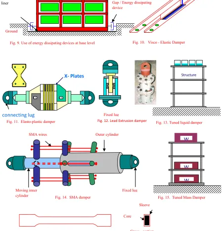
Fig. 9. Use of energy dissipating devices at base level Fig. 10. Visco - Elastic Damper
[image:7.612.68.521.218.684.2]International Journal of Emerging Technology and Advanced Engineering
Website: www.ijetae.com (ISSN 2250-2459, Volume 2, Issue 7, July 2012)
445
composed by Low Damping Rubber Bearings (LDRBs) acting as passive seismic isolators, and Magneto-rheological (MR) dampers, acting as semi-active controlling devices. The analyses showed that significant reduction of the building accelerations (up to 50%) can be achieved with the hybrid system.V. HYBRID BASE ISOLATION WITH PASSIVE ENERGY
DISSIPATERS
The energy dissipating devices (ref. Fig. 9 to 16) mainly dissipate the earthquake energy and thereby reduce the effect of the earthquake on the structure. These devices can be used at the base of the structure or in superstructure at appropriate locations. They can be used in combination with passive base isolation techniques. The different devices developed world over are shown in Fig. 9 to 16.
Structure responses can be controlled by using Visco-Elastic dampers (VEDs) [2], which are made of linear springs and dash pots provided in parallel and are generally used in bracings of building frame or at ground level.
Elasto-Plastic Dampers (EPDs) [8],[18], [19] are made of number of small ‘X’ shaped plates, which yield at small deformation thereby dissipate high amount of energy.
Lead Extrusion dampers (LEDs) [8] work on the principle of extrusion of lead. It absorbs vibration energy by plastic deformation of the lead, during which mechanical energy is converted into heat, lead gets heated up and on being extruded, lead re-crystallizes immediately and recovers its original mechanical properties before next extrusion
Tuned Liquid dampers (TLDs) [8] are rigid wall containers filled up to required height with a liquid (generally water) to match the sloshing frequency of the liquid with that of the structure. These containers are generally placed on the top of the structure. The vibration energy is dissipated in the sloshing action of the liquid.
Shape Memory Alloy Dampers (SMADs) [8], [18], [19] made of nickel-titanium (Ni-Ti) alloy wires has an interesting pseudo-elastic property by which the alloy regains its initial shape when external load is removed. This property is useful in putting back the structure to its original shape. Also it can sustain large amount of inelastic deformation.
An un-bonded brace, a technique developed in Japan, consists of developing a brace which is prevented from buckling by way of providing a metal collar filled with concrete at the center of brace and a thin layer of viscous material which allows slip and Poisson’s ratio expansion at the slip surface provide relative movement between the
steel collar and surrounding concrete. This protects the brace from buckling and allows proper dissipation of energy in the brace through stable hysteresis loop. A buckling restrained or core loaded or non-buckling brace developed in IIT, Madras also works on the similar lines and dissipates the earthquake energy. [10], [11]
Tuned Mass Damper (TMD) [2] is a spring – mass damper device generally connected to the structure at its top. It has been used as a passive control device for response reduction of tall buildings.
Examples Of Isolated Structures In Different Countries – Few examples of isolated structures are William Clayton building, New Zealand [8], Medical Centre of the Italian Navy (Sarvesh K. Jain And Shashi K. Thakkar, 2004, LRB+MRD system), Nam-Han River bridge on the Young-dong expressway Seoul, Korea (Sun Young Lee, et al., 2004, LDRB+MRD system), Experimental building at IIT, Guwahati, India [8] etc.
The number of seismically isolated buildings in Japan, Russia, China, USA, Italy, Armenia, New Zealand were 1600, 500, 458, 100, 27, 14 and 11 respectively up to December 2002, 2003 [13] and every year the number of isolated structures are increasing.
VI. DYNAMIC ANALYSIS OF BASE ISOLATED STRUCTURES
[9]
Generally the base isolated buildings are designed such that the superstructure above isolators and base structure below isolators remain elastic and non-linearity is contained within the isolators. The equations of motion used are as follows –
)
(
u
gu
bMR
Ku
u
C
u
M
(1)0
)
(
)
(
(
c b b b b b g b b g Tf
f
u
K
u
C
u
u
M
u
u
R
u
M
R
(2)International Journal of Emerging Technology and Advanced Engineering
Website: www.ijetae.com (ISSN 2250-2459, Volume 2, Issue 7, July 2012)
446
The force generated in the laminated bearings can be modeled by a visco-plastic model asx y p e x
p
u
k
k
u
z
k
fx
(
)
(3)y y p e y p
y
k
u
k
k
u
z
f
(
)
(4)where ke= pre-yield stiffness, kp= post-yield stiffness, uyis the yield displacement, zx and zy are dimensionless hysteretic variables defined by Park et al.
The force generated in the sliding bearings can be modeled by a visco-plastic model as
x x
p
x
k
u
uNz
f
(5)y y
p
y
k
u
uNz
f
(6)where μ is the coefficient of friction and N is the average normal force at the bearing.
VII. CODAL PROVISIONS FOR BASE ISOLATED
STRUCTURES –FEMA450[14],[15]
As of now codes of many countries do not have provision of guidelines for design of base isolated structures. However countries like US have developed guidelines for the design of base isolated structures which contain in FEMA (Federal Emergency Management Agency) 450. Some of the provisions are given in Table 1 which shows Protection Provided by NEHRP Recommended Provisions for Minor, Moderate and Major Levels of Earthquake Ground Motion.Lower limit bounds for different properties of isolators are given in table 2. TABLE I
NEHRP RECOMMENDATIONS
Risk Category
Earthquake Ground Motion Level
Minor (MMS Intensity ≤ V)
Moderate (MMS Intensity >
V ≤ VII)
Major (MMS Intensity >
VII)
Life Safety a F, I F, I F, I
Structural
damage b F, I F, I I
Non structural
damage c
(contents damage)
F, I I I
a Loss of life or serious injury is not expected.
b Significant structural damage is not expected.
c Significant nonstructural (contents) damage is not expected.
F Indicates fixed base, I indicates isolated.
TABLE II
LOWER LIMIT BOUNDS FOR DIFFERENT PROPERTIES OF ISOLATORS
Design Parameter ELF procedure Dynamic properties
Response
spectrum Response history
Design displacement - D
DD
D= (g/4π
2)(S
DiT
D/B
D)
-
-
Total design displacement - D
TD
T> 1.1 D
>
0.9 D
T>
0.9 D
TMaximum displacement - D
MD
M= (g/4π
2)(S
MIT
M/B
M)
- -Total Maximum displacement -
D
TMD
TM> 1.1 D
M> 0.8 D
TM> 0.8 D
TMDesign shear - V
b(at or below the isolation system)
V
b=k
DmaxD
D> 0.9 V
b> 0.9 V
bDesign shear V
s(regular super structure)
V
s=
k
DmaxD
D/R
I> 0.8 V
s> 0.6 V
sDesign shear V
s(irregular super structure)
V
s=
k
DmaxD
DR
I> 1.0 V
s> 0.8 V
sInternational Journal of Emerging Technology and Advanced Engineering
Website: www.ijetae.com (ISSN 2250-2459, Volume 2, Issue 7, July 2012)
447
Where –DD = The design displacement at the center of rigidity of the isolation system
DM = Maximum displacement at the centre of rigidity of the isolation system
g = acceleration due to gravity
SDI = Design 5% damped spectral acceleration parameter at one Second period as determined in Chapter 3
SMI = Design 5% damped spectral acceleration parameter at one Second period as determined in Chapter 3
T = Effective period of seismically isolated structure at the design displacement in the direction under consideration
BD & BM = Numerical co-efficient related to the effective damping of the isolation system at the design and maximum displacements.
W = Seismic weight above the isolation interface kDmax = Maximum effective stiffness of the isolation system at the design displacement in the horizontal direction under consideration.
RI = Numerical co-efficient related to the type of seismic force resisting system above isolation system which takes the values of 1.0 ≤ RI = 3/8 R ≤ 2.0 as defined in the code.
VIII. TESTING OF ISOLATORS-
Code requires that at least two full sized specimens of each type of isolator be tested. The tests required are a specified sequence of horizontal cycles under DL + 0.5LL from small horizontal displacements up to DTM. In addition, tests are also carried out for the maximum vertical load 1.2DL + 0.5LL + Emax and for the minimum load 0.8DL – Emin where Emax and Emin are the maximum downward and upward load on the isolator that can be generated by an earthquake.
IX. SUITABILITY OF SEISMIC BASE ISOLATION [9]
Implementations of base isolation techniques are generally effective in conditions – a) The soil strata on which structure is standing does not produce long period ground motion. b) The structure is fairly squat with sufficiently high column loads. c) The site permits horizontal displacement at base of the structure of the order of 200mm or more. d) Lateral loads due to wind are less than approximately 10% of the weight of the structure.
X. BASE ISOLATION ON SOFT SOILS
Soft soils produce long period waves on structures and a structure with long period will attract lesser earthquake
forces. Hence a question is generally raised on the effectiveness of base isolation in case of soft soil foundation. Kelly and others after performing some experiments have concluded that the base isolation on soft soils can be effective in case the load on the isolator is large and the sizes of the isolation system are sufficiently large to accommodate the large displacements.
XI. BASE ISOLATION FOR NEAR FAULT MOTION
A number of accelerograms recorded in the recent past at near fault locations raise a question about the effectiveness of isolation system due to mainly two reasons –
The ground motion normal to fault trace is richer in long period spectral components than that parallel to the fault. The fault normal and fault parallel motions are more or less un-correlated. The fault parallel motions often exhibit higher spectral acceleration components at short period than the fault normal motion. The resultant maximum displacement is due to the normal component of the near fault motion. The contributions from the parallel components in the near fault motion may be ignored.
The second aspect of the near field ground motion that strongly impacts the isolation system is the presence of long duration pulses. The ground motion may have one or more displacement pulses, which have peak velocities of the order of 0.5m/sec and the duration in the range of 1- 3
secs. The pulses will have a large impact on isolators and may lead to large displacements of isolator. The large isplacements can be accommodated by providing large isolators.
1E-4 1E-3 0.01 0.1 1 10
0.0 0.2 0.4 0.6 0.8 1.0 1.2
G
/Gm
ax
Shear Strain(%) Modulus reduction curve
International Journal of Emerging Technology and Advanced Engineering
Website: www.ijetae.com (ISSN 2250-2459, Volume 2, Issue 7, July 2012)
448
A comparative study of performance of various isolation systems has been carried out by Jangid and Kelly and they have concluded that EDF type isolation system is optimum choice of design for site located near faults. [9]XII. BASE ISOLATION BUILDINGS WITH SSI[9]
The influence of Soil Structure Interaction (SSI) and possible effects of building and foundation rocking have
been examined by Novak M. and Henderson P. The effect of soil structure interaction on the modal properties and seismic forces is small when isolators are much more flexible than soil. However if the flexibility of isolator and
the soil is comparable, then soil may contribute to the building behavior.
XIII. FUTURE TRENDS IN BASE ISOLATION
Many of the base isolation techniques described above involve the materials, which are susceptible to deterioration with time. . Regular inspection and maintenance of the system is required. Special measures need to be taken for fire protection. As such it is desirable to develop such an isolator, which has a life span equal to the life of a structure, free from effects of environment and fire. Also it should be free from maintenance. Hence it will be an ideal case if researchers develop an isolator using materials which are unaffected by environment or affected by it to very low extent like natural earth of specific qualities having inherent properties of spring action and friction.
The equivalent spring constants and damping co-efficient for foundations resting on soil can be worked out using equations given in the table 3. Equations for damping accounts for material as well as radiation effects.
From the above equations which are valid for low strains, it can be seen that the spring stiffness is more for large size foundations and for greater value of shear modulus G. Also it is dependent on Poisson’s ratio of soil. Thus the spring values of the soil can be altered by varying the above parameters by choosing soil of appropriate properties. In similar way the damping properties of the soil medium can be altered. Also the effect of damping and isolation can be obtained by allowing the structure to slide on a soil medium to required extent. However, in the case of using soft geological materials such as soil, sand, pulversied granite etc, the material will see large strains. Typically for a soil the variation of G with strain is shown in the fig 17. It is evident from the graph that during the non-linear behavior of the soil, the G value decreases for larger strains which in turn will have lesser soil stiffness and increased damping leading to enhanced isolation effect. The increased damping with strains as shown in the figure will allow to control the displacements.
TABLE III
SPRING CONSTANTS AND DAMPING COEFFICIENTS FOR FOUNDATIONS ON HOMOGENEOUS HALF-SPACE [16]
Direction of Motion
Equivalent Spring Constant for Rectangular Foundation
Equivalent Damping Coefficient
Horizontal KH = 2(1+ ν)G βX√(BL)
CH =C1KHR√( ρ/G)
Rocking KR = (G/(I- ν)) βψ
BL2 CR =C2KRR√( ρ/G)
Vertical Kν=(G/(I-ν))βν√(BL) CV =C3KVR√( ρ/G)
Torsion - CT = √(KTIT )/(1+2IT
/ΡR5) Where -
Ρ = mass density of soil
Vs = Shear wave velocity of soil medium G = ρ Vs2
ν = Poisson’s ratio of soil medium
R = equivalent radius for rectangular foundation (R= √BL/π for translation and R= 4√4BL3 / 3π for rocking).
B = width of the foundation perpendicular to the direction of horizontal excitation
L = length of the foundation in the direction of horizontal excitation
I0 = total mass moment of inertia of structure and foundation about the rocking axis at the base
IT = polar mass moment of inertia of structure and foundation βx, βψ, and βv are constants depending on ratio L/B
International Journal of Emerging Technology and Advanced Engineering
Website: www.ijetae.com (ISSN 2250-2459, Volume 2, Issue 7, July 2012)
449
Properties of different types of soils occurring in the nature are given in table 4.XIV. CASE STUDY
In the past, experiments have been performed on structures resting on sand layer [9], Such systems dissipate earthquake energy before reaching to the structure and are useful for wide range of frequencies. Varieties of soil are available in abundance in nature and each type of soil exhibit different properties. The same soil exhibits different properties in dry and wet conditions or static and dynamic conditions. The shear modulus in static and that in dynamic
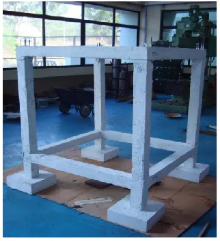
conditions varies largely. The properties of the soil can be altered by providing geo-membrane in the soil [5]. The cost of soil is meager and needs no maintenance cost. Knowing these facts, clean river sand was tried as base isolation material and experiments were conducted on a RCC frame model having raft foundation and isolated footing as shown in Fig.18.
River sand, having engineering properties shown in Table 5 [20], is used in the experiments.
The size of the model is 1.2 x 1.2 x 1.5 m and the raft model is provided with a base raft of size 1.5 x 1.5 x 0.1 m and isolated footing model is provided with footings of size 0.35 x 0.35 x 0.1 m. The size of the cross section of beams
TABLE IV
REPRESENTATIVE VALUES OF ANGLE OF FRICTION FOR SANDS AND SILTS AND REPRESENTATIVE VALUES OF COHESION FOR CLAYS.
Sr.
no. Soil (sands and silts) of friction - degrees Effective angle Sr. no. Soil (Clay) in kN/sqm. Cohesion 1. Sand, round grains, uniform 27 to 34 I. Very soft clay < 12 2. Sand, angular, well graded 33 to 45 II. Soft to medium clay 12 – 25
3. Sandy gravels 35 to 50 III. Silt clay 50 – 100
4. Silty sand 27 to 34 IV. Very stiff 100 – 200
[image:12.612.71.537.344.684.2]5. Inorganic silt 27 to 35 V. Hard > 200
[image:12.612.93.254.482.658.2]International Journal of Emerging Technology and Advanced Engineering
Website: www.ijetae.com (ISSN 2250-2459, Volume 2, Issue 7, July 2012)
450
and columns is 0.1 x 0.1 m. and roof slab thickness is 0.05 m. A metallic box of size 2.0 m x 2.0 m x 1.2 m height is used and is filled with 300 mm thick layer of the dry sand(RAFDRY/ISODRY) / wet sand (RAFWET /ISOWET) / dry sand with geo-membrane (RDSGM/IDSGM) / wet sand with geo-membrane (RAFWETG / ISOWETG) in separate cases. The box is fixed on tri-axial shake table and RCC model is kept on the
sand layer. The locations of the accelerometers fixed on the
TABLE V
RIVER SAND PROPERTIES
Property Value Property Value
Gravel 5.6% Cu 7.37
Coarse sand 19.4% Cc 1.12 Medium Sand 53% γdmax 1.71g/cc Fine Sand 17.6% γdmin 1.40g/cc Silt + Clay 4.4% Sp.gravity 2.66
D60 1.18mm emax 0.77
D10 0.16mm emin 0.48
[image:13.612.340.556.167.243.2]D30 0.46mm
Fig.18c - RCC model with raft base with accelerometer locations
Z
[image:13.612.45.278.169.351.2]Y X
Fig. 19d – Acceleration time history for A6 signal for FXRAF and RAFWETG cases for zone III of IS 1893 excitation.
[image:13.612.340.552.288.383.2]Fig. 19a – Acceleration time history for A6 signal for FXRAF and RAFDRY cases for zone III of IS 1893 excitation.
[image:13.612.80.242.429.625.2]Fig. 19b – Acceleration time history for A6 signal for FXRAF and RDSGM cases for zone III of IS 1893 excitation.
[image:13.612.340.556.443.637.2] [image:13.612.340.559.570.676.2]International Journal of Emerging Technology and Advanced Engineering
Website: www.ijetae.com (ISSN 2250-2459, Volume 2, Issue 7, July 2012)
451
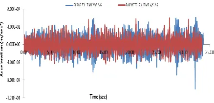
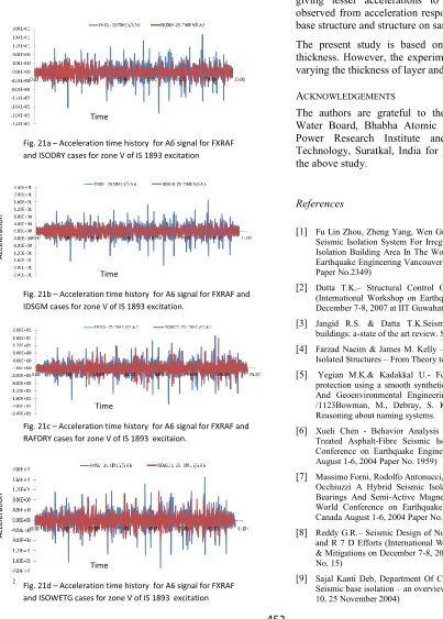
model are indicated in Fig. 18c. Different tests were conducted on the model.The initial research studies show encouraging results. The comparison of acceleration responses recorded at roof level accelerometer A6 for raft model FXRAF and RAFDRY, RDSGM, RAFWET and RAFWETG cases for zone III excitation level of IS 1893 are shown in Fig. 19a to 19d. Also responses for isolated footing model FXISO are compared with ISODRY, IDSGM, ISOWET and ISOWETG cases for zone V excitation of IS 1893 and are shown in Fig.21a to 21d. The response acceleration
comparison shows that the peak accelerations are less in case of models on sand layer as compared to fixed base case.
The FFTs for raft cases (Fig. 20a) as well isolated footing (Fig 20b) cases clearly indicates that there is a reduction in the natural frequency of the model
XV. DISCUSSIONS AND CONCLUSIONS
[image:14.612.321.517.284.426.2]The above studies reveal that the provision of sand layer below base of structure reduces frequency of the structure and reduction in frequency is more with more excitation
[image:14.612.98.285.286.434.2]Fig. 20a - FFTs showing comparison of frequencies of RAFDRY and R DSGM cases with FXRAF case for zone III of IS 1893 excitation.
Fig. 20b - FFTs showing comparison of frequencies of RAFWET and RAFWETG cases with FXRAF case for zone III of IS 1893 excitation.
.
Fig 22a - FFTs showing comparison of frequencies of ISODRY and IDSGM cases with FXISO case for zone V of IS 1893 excitation.
[image:14.612.330.523.506.637.2] [image:14.612.93.301.506.640.2]International Journal of Emerging Technology and Advanced Engineering
Website: www.ijetae.com (ISSN 2250-2459, Volume 2, Issue 7, July 2012)
452
force. As the frequencies are reduced, the response of thestructure also reduces. The part of the excitation energy gets dissipated in the movement and friction of the sand layer, thereby the energy reaching to the structure reduces giving lesser accelerations to the structure, which is observed from acceleration response comparisons of fixed base structure and structure on sand layer.
The present study is based on sand layer of 300 mm thickness. However, the experiments can be performed by varying the thickness of layer and different types of soil.
ACKNOWLEDGEMENTS
The authors are grateful to the Management of Heavy Water Board, Bhabha Atomic Research Center, Central Power Research Institute and National Institute of Technology, Suratkal, India for permitting and supporting the above study.
References
[1] Fu Lin Zhou, Zheng Yang, Wen Guang Liu And Ping Tan - New
Seismic Isolation System For Irregular Structure With The Largest Isolation Building Area In The World (13 th World Conference on Earthquake Engineering Vancouver, B.C., Canada August 1-6, 2004 Paper No.2349)
[2] Dutta T.K.– Structural Control Of Seismic Disaster Mitigation
(International Workshop on Earthquake Hazards & Mitigations on December 7-8, 2007 at IIT Guwahati, India, Paper No. 4)
[3] Jangid R.S. & Datta T.K.Seismic behavior of base isolated
buildings: a-state of the art review. Structural and Building Board
[4] Farzad Naeim & James M. Kelly – A book on ‘Design of Seismic
Isolated Structures – From Theory to Practice’ published in 1999.
[5] Yegian M.K.& Kadakkal U.- Foundation isolation for seismic
protection using a smooth synthetic liner. Journal Of Geotechnical And Geoenvironmental Engineering © Asce / November 2004 /1123Bowman, M., Debray, S. K., and Peterson, L. L. 1993. Reasoning about naming systems.
[6] Xueli Chen - Behavior Analysis And Application Research For
Treated Asphalt-Fibre Seismic Isolation Cushion (13 th World Conference on Earthquake Engineering Vancouver, B.C., Canada August 1-6, 2004 Paper No. 1959)
[7] Massimo Forni, Rodolfo Antonucci, Alessandra Arcadi And Antonio
Occhiuzzi A Hybrid Seismic Isolation System Made Of Rubber Bearings And Semi-Active Magneto-Rheological Dampers (13 th World Conference on Earthquake Engineering Vancouver, B.C., Canada August 1-6, 2004 Paper No. 2177)
[8] Reddy G.R.– Seismic Design of Nuclear Facilities in India – Issues
and R 7 D Efforts (International Workshop on Earthquake Hazards & Mitigations on December 7-8, 2007 at IIT Guwahati, India, Paper No. 15)
[9] Sajal Kanti Deb, Department Of Civil Engineering, Iit, Guvahati –
[image:15.612.55.458.164.727.2]Seismic base isolation – an overview. (Current Science, Vol. 87, No. 10, 25 November 2004)
Fig. 21b – Acceleration time history for A6 signal for FXRAF and IDSGM cases for zone V of IS 1893 excitation.
Time
A
cc
el
er
at
io
n
Fig. 21a – Acceleration time history for A6 signal for FXRAF and ISODRY cases for zone V of IS 1893 excitation
A
cc
el
er
at
io
n
Time
Fig. 21c – Acceleration time history for A6 signal for FXRAF and RAFDRY cases for zone V of IS 1893 excitaion.
A
cc
el
er
at
io
n
Time
Fig. 21d – Acceleration time history for A6 signal for FXRAF and ISOWETG cases for zone V of IS 1893 excitation
A
cc
el
er
at
io
n
[image:15.612.50.281.183.277.2]International Journal of Emerging Technology and Advanced Engineering
Website: www.ijetae.com (ISSN 2250-2459, Volume 2, Issue 7, July 2012)
453
[10]Satish Kumar S.R.– Research On Earthquake Resistant Structural
Design At IIT, Madras. (International Workshop on Earthquake Hazards & Mitigations on December 7-8, 2007 at IIT Guwahati, India, Paper No. 12)
[11]Satish Kumar, K. Muthumani & N. Gopalkrishnan & R. Sreekala –
Design Scheme For Seismic Retrofitting Of Structures Using Visco-Elastic Damper Devices. (13th Symposium on Earthquake Engineering held at IIT, Roorkee, from Dec 18-20, 2004, Paper No. 136)
[12]Veto Verma, Reddy G.R., Vaze K.K. & Khushwaha H.S. – Base
isolation strategies for structures and components.
[13]Alessandro Martelli - State-of-the-Art on the Development and Application of Seismic Vibration Control Techniques and Some Innovative Strengthening Methods for Civil and Industrial Structures (17 th International Conference on Structural Mechanics in Reactor Technology (SMiRT 17) Prague, Czech Republic, August 17 –22, 2003 Paper # K13-4)
[14]FEMA 450, CHAPTER 13 – Seismically isolated structure design
requirements.
[15]FEMA 450, CHAPTER 13 commentary – Seismically isolated
structure design requirements.
[16]IAEA TECDOC 1347- Consideration Of External Events In The
Design Of Nuclear Facilities Other Than Nuclear Power Plants, With Emphasis On Earthquakes.
[17]Ivan Skinner R, William H. Robinson & Graeme H. Mcverry – A
book on ‘An Introduction to Seismic Isolation’.
[18]Parulekar Y.M., Reddy G.R., Vaze K. K., Ghosh A.K.- Seismic
response control of complex piping system using elasto-plastic dampers – Experiments and analysis. (International Workshop on Earthquake Hazards & Mitigations on December 7-8, 2007 at IIT Guwahati, India, Paper No. 55)
[19]Parulekar Y.M., Reddy G.R., Vaze K.K., Ghosh A.K., Khushavha
H.S., Muthumani K. & Sreekala – Passive Seismic Control Of Piping System Using Shape Memory Alloy Damper. (13th Symposium on Earthquake Engineering held at IIT, Roorkee, from Dec 18-20, 2004, Paper No. 149)
[20]BRNS report 2009 – Board of Research in Nuclear Sciences,