Journal of Chemical and Pharmaceutical Research, 2014, 6(7):585-593
Research Article
CODEN(USA) : JCPRC5
ISSN : 0975-7384
FPGA-based implementation of circular interpolation
Mingyu Gao, Jiaxiang Lou, Jilong Ye and Zhanxiong Wu
Hang Zhou Dian Zi University, Hang Zhou, China
______________________________________________________________________________
ABSTRACT
Owing to arithmetic speed’s influence of computer software, the accuracy and speed of numerical control system’s feed based on software interpolation are subject to certain restrictions. FPGA-based realization of four kinds of hardware circular interpolation algorithm in this paper, the hardware logic designed with verilog hardware description language, and the actual trajectory verified by ModelSim simulation and coordinate draw point; ARM+FGPA-based implementations of four circular interpolation algorithms do the verifications in two axes architecture automatic CNC machine tool. From the results, improved min-error interpolation has the best precision and efficiency among the four interpolations. So this interpolation algorithm has superior practical value on CNC machine tools and industrial robots.
Key words: DDA interpolation, min-error interpolation, FPGA, CNC system
______________________________________________________________________________
INTRODUCTION
Machine tool motion is achieved through interpolation in CNC systems, so interpolation algorithm [1-3] affects the processing speed and precision directly. Interpolation task is to calculate the coordinates of several intermediate points between the start and end of the part’s contour, making the coordinates of track are set by the interpolation curve. Since calculation’s time of each point directly affect the control speed of the CNC system, and the accuracy affect the final geometric precision [4-5]. So the interpolation algorithm is critical to performance of CNC system devices, it is seen as the core technology of CNC system devices.
There are high requirements for real-time motion control in modern high-speed CNC systems, although software interpolator has advantages, the software interpolation [6] affects by restriction of synchronous output. So the speed, accuracy, and efficiency of interpolator algorithm are difficult to meet the performance requirements of high-speed and real-time control. The way to solve this problem is to give full play to the respective advantages of software and hardware, the real-time demanding task implemented by specially designed hardware. Due to the design of FPGA is parallel, multi-threaded and online programming, and FPGA has the advantages of both high speed and low cost, while overcomes the shortage of dedicated processor’s inflexibility. Therefore, FPGA-based hardware interpolation [7] has a high practical value, and it is suitable for high efficiency and high precision of the workplace. Finally, the transmission of instructions, parameters between ARM [8] processor and FPGA [9] is through the parallel bus of FSMC, which meets the requirement of real-time better.
BY-POINT COMPARISON INTERPOLATION
Assuming that arc radius is r, to processing a quarter of the first quadrant circle, starting point is and end point is, so the arc equation is:
2 2 2
x
+
y
=
r
(1)Then write the deviation judgment formula:
2 2 2
F
= + −
x
y
r
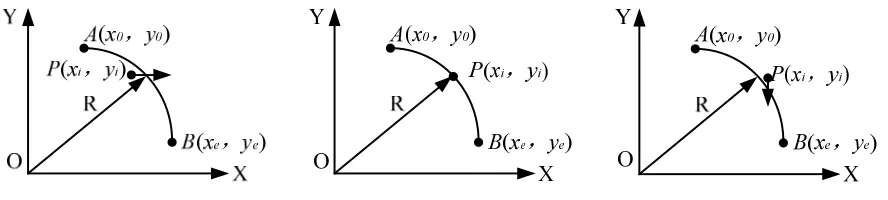
(2)We can summary out the relative position of relationship between the arc and the target, as follows: When
F
<
0
the fixed point P is inside of the set arc;When
F
=
0
, the fixed point P falls on the given arc; [image:2.595.96.540.265.365.2]When
F
>
0
, the fixed point P is outside of the set arc.Fig. 1: Sketch of by-point comparison interpolation
From Fig. 1, we can deduce that, when the deviation judgment formula of point P corresponding to is less than 0, then
X axial feeds and the next point is
( ,
x y
i i+
1)
, the deviation judgment formula is re-calculated as follow:2 2 2
1 1
(
i,
i)
(
1)
( ,
i i)
2
1
F x
+y
+=
x
+ +
y
− =
r
F x y
+
y
+
(3)When the deviation judgment formula of point P corresponding to is greater or equal to 0, then -Y axial feeds and the next point is
(
x
i+
1,
y
i)
, the deviation judgment formula is re-calculated as follow:2 2 2 1 1
(
i,
i)
(
1)
( ,
i i) 2
1
F x
+y
+= +
x
+
y
− =
r
F x y
+
x
+
(4)Finally, the start point is on the circle, so we can give out the initial value of deviation judgment formula:
0 0
( ,
)
0
F x y
=
(5)By-point comparison algorithm implemented on FPGA is relatively simple, and the required logic resource is not too much, but the algorithm outputs only signal axle pulse not both when feeding, so the processing efficiency can’t be higher.
DDA INTERPOLATION
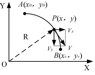
Fig. 2: Sketch of DDA interpolation
From Fig. 2, assuming the arc radius is r, so the equation of circle is
x
2+
y
2=
r
2. Partial derivative obtained for x,we can know:
dy
x
dx
= −
y
(6)From the DDA interpolation, the interpolation formulas of both axils are as follows:
1 1 1
m m m
x i
i i i
x
x
v
t
k
y
= = =
=
∑
∆ =
∑
• ∆ =
∑
(7)1 1 1
m m m
y i
i i i
y
y
v
t
k
x
= = =
=
∑
∆ =
∑
• ∆ = −
∑
(8)Lastly, we give out the initial value of accumulated overflow formula, because accumulated value is compared with the long axis and short axis, it’s always less than or equal to the long axis, there must be a certain lag. So the initial value of the register need loading value firstly. Here we take a preset number of half-loading interpolation for improving the speed and accuracy of the interpolation.
MIN-ERROR INTERPOLATION
Min-error interpolation [12] is that according the minimum deviation among A to N, B to N and C to N to do each feed. This interpolation is realized by comparing the distance of three points, so the realization of FPGA hardware interpolation algorithm needs a large amount of register variables, which makes waste of the logical resource when applying for more register variables.
{
[image:3.595.238.382.586.708.2]{
{
on the arc, and also
A x
(
i+
1,
y
i−
1)
,B x y
( ,
i i−
1)
,C x
(
i+
1,
y
i)
. Arc equation isx
2+
y
2=
r
2. Then deviation judgment formula is:2 2 2
i i i
F
=
x
+
y
−
r
(9)2 2
1
2
(
x
i1)
(
y
i1)
r
F
i2
x
i2
y
i2
n
=
+
+
−
− = +
−
+
(10)2 2
2
2
(
1)
2
1
i i i i
n
=
x
+
y
−
− = −
r
F
y
+
(11)2 2 2
3
(
x
i1)
y
ir
i2
i1
n
=
+
+
− = +
F
x
+
(12)By comparing the distance of n1, n2 and n3, we can know the feed direction:
① When n1 is the smallest, the curve closed the point , so the feed direction feeds both and , the new deviation
formula is:
2 2 2
i+1
(
i1)
(
i1)
i2
i2
i2
F
=
x
+
+
y
−
−
R
= +
F
x
−
y
+
(13)② When n2 is the smallest, the curve closed the point , so the feed direction is , the new deviation formula is:
2 2 2
i+1 i
(
i1)
i2
i1
F
=
x
+
y
−
−
R
= −
F
y
+
(14)③ When n3 is the smallest, the curve closed the point , so the feed direction is , the new deviation formula is:
2 2 2
i+1
(
i1)
i i2
i1
F
=
x
+
+
y
−
R
= +
F
x
+
(15)Finally, the start point is on the circle, so we can give out the initial value of deviation judgment formula:
0
0
F
=
(16) [image:4.595.230.389.540.667.2]Assuming the current point is at , According to the principle of min-error interpolation and distance of n1, n2 and n3, we can get the next pulse feed direction. The output pulse can be made uniformly, quickly and efficiently, and the interpolation algorithm is easier to be realized. But this interpolation needs much logic elements.
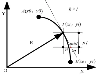
Fig. 4: Sketch of improved min-error interpolation
IMPROVED MIN-ERROR INTERPOLATION
like point mid. This interpolation uses the less logic elements because of the less register variables. So this interpolation can be used well in the limited logic elements of FPGA.
As shown in Fig4, now the processing point is located in the slope |k|> 1, assuming the radius of circular arc is r, start point is
A x y
( ,
0 0)
, and end point isB x y
( ,
e e)
. Then deviation judgment formula is:2 2 2
i i i
F
=
x
+
y
−
r
(17)Due to p1
(
x
p1,
y
i+1)
, so it is satisfies with the formulax
p12+
y
i+12=
r
2, whichy
i+1= −
y
i1
.So we can know2 2 2 2 2 2
1 1
(
1)
2
1
p i i i i i
x
= −
r
y
+= −
r
y
−
=
x
− +
F
y
−
.Taking
d
1=
x
p12and 2 2(
1
)
22
mid i
d
=
x
=
x
+
, then:1 2
5
2
4
i i i
d
−
d
=
y
− − −
x
F
(18)Remove the denominator we can get formula:
1 2
4(
d
−
d
)
=
8
y
i−
4
x
i− −
5 4
F
i(19)We can know whether the shorter axis feeding by judged the symbol of
d
1−
d
2:① when
d
1− ≥
d
20
, the curve is closed the point m, then the feed direction is .New deviation judgment formula:2 2 2
1 1 1
2
2
2
i i i i
F
+=
x
++
y
+− = +
r
F
x
−
y
+
(20)② when
d
1− <
d
20
, the curve is closed the point n, then the shorter axis does nothing .New deviation judgmentformula:
2 2 2
1 1 1
2
1
i i i i
F
+=
x
++
y
+− = −
r
F
y
+
(21)Finally, the start point is on the circle, so we can give out the initial value of deviation judgment formula:
0 0
( ,
)
0
F x y
=
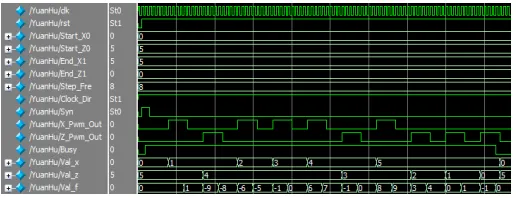
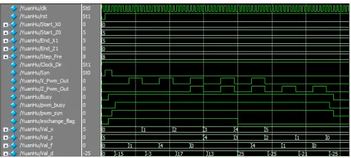
(22) [image:5.595.183.441.616.715.2]waveforms of a radius is 5 of 1/4 smooth round. Which coordinates the arc start point is
(5, 0)
and end point is(0, 5)
. [image:6.595.183.439.233.344.2]Fig. 6: Simulation waveform of DDA interpolation
Fig. 7: Simulation waveform of min-error interpolation
Fig. 8: Simulation waveform of improved min-error interpolation
Here are the generic signals in the simulation waveform:
clk
is the clock signal;rst
is the reset signal;_
0
Start
X
,Start
_
Z
0
,End
_
X
1
andEnd
_ 1
Z
represent the starting point and end point coordinates;Syn
is a synchronization start signal;X
_
Pwm Out
_
andZ
_
Pwm Out
_
is the interpolation pulse output;Busy
indicates when the interpolation is finish;Val
_ x
andVal
_
z
show the current coordinate values. InFig.5, the
Val
_
f
represents the deviation judgment formula . In Fig.6,Sum
_
X
andSum Z
_
represent twoaccumulator registers in DDA. In Fig. 7,
Val
_
f
,Val n
_
1,Val n
_
2 andVal n
_
3represent the deviationjudgment formula
F
i,n
1,n
2 andn
3.THE ANALYSIS OF SPEED AND ACCURACY
[image:6.595.183.438.369.484.2]by-point comparison DDA
1 2 3
1 2 3 4 5 6
5 4
1 2 3
1 2 3 4 5 6
5 4
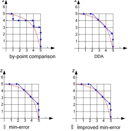
Fig. 9: Four kinds of interpolation trajectory about arc
[image:7.595.175.438.82.352.2]Where the blue line represents the actual trajectory interpolation, red represents the ideal arc. The arrows indicate the direction of servo feed. The comparison of the four interpolations for processing the same circular arc is shown as table 1. Table 1 also lists the number of processing steps (inversely related to the number of steps and the processing speed), processing accuracy (error) and logic resource used, while the error can be obtained with the normalized values.
Table 1: processing speed , error and logic resources of four kinds circular interpolation
Pulse and error by-point comparison DDA Min-error Improved min-error Pulse
(unit:minimum step) 10 8 7 7
Error
(unit:minimum step) 0.877 0.385 0.385 0.385
logic elements 690 724 792 724
According to the diagram of simulation and interpolation trajectories, we can learn that:
① by-point comparison interpolation, each feed direction only could be one of the axes, so the two feed axes can't be
achieved simultaneously, the processing required 10 steps, and normalization of errors is 0.877, but the logic elements required are less.
② DDA, the initial value of accumulator register is set to a half of the major axis with semi-loaded method. X axis and
Z axis can feed simultaneously, but the feed must under the condition of overflow of the accumulator register, the processing of this arc requires 8 steps, normalization of errors is 0.385, and the logic elements required are less than min-error interpolation.
③ min-error interpolation, determine the next pulse feed direction by error of each interpolation directly, the direction
is the same as the closest point among the three points. X axis and Z axis can feed simultaneously and no need to wait the overflow of the accumulator register, so the processing efficiency would be higher. The processing of this arc requires 7 steps, normalization of errors is 0.385, but the logic elements required are more than other interpolations.
min-error interpolation.
[image:8.595.170.452.152.340.2]FPGA-based hardware interpolator has achieved good results in the processing tests of efficiency and accuracy. And real-time of communication between ARM and FPGA by FSMC bus is good. Meanwhile, to the dedicated interpolation controller, the cost of this hardware interpolator can be well controlled. Fig.10 is the actual processing test of improved min-error interpolation.
Fig. 10: The actual processing test of improved min-error interpolation
CONCLUSION
ARM and FPGA-based hardware interpolator has a high real-time performance and a good cost advantage. To this interpolator realized by improved min-error interpolation, by-point comparison is worse in terms of speed and precision, and DDA is worse in terms of process’s speed despite of the same precision. The logic elements of improved min-error interpolation are less than min-error interpolation, so the proposed hardware interpolator is worthy of application and generalization.
By-point comparison interpolation is suitable for the general economical CNC systems, DDA can be used in low-end requirements which don’t need high processing efficiency because of its high process precision, while improved min-error interpolation is widely used in the high precision CNC systems and industrial robots.
REFERENCES
[1]PANG, Qi-shou, and Yu-sheng FENG. Manufacturing Automation 6 (2009): 018.
[2]Hua, Yan, Zuo Jian-min, and Wang Mu-lan. Mod ern Manufacturing Engineering 9 (2007): 016.
[3]TAN, Yong, Zhi-sen WANG, and Xiao-jing YAN. Journal of Hefei University of Technology (Natural Science) 6
(2004): 008.
[4]Guoyong Zhao, Hongjing An, Qingzhi Zhao, Journal of Computers, vol 8, no 6 (2013), 1512-1519, jun 2013.
[5]G Zhixiang Shao, RuifengGuo, Jie Li, JianJun Peng, Journal of Software, vol 6, no 10 (2011), 2056-2063, oct 2011.
[6]Chen, Z. Y., W. Guo, and C. X. Li. Industrial Electronics and Applications, 2006 1ST IEEE Conference on. IEEE,
2006.
[7]WANG, Fang, and Kun-qi WANG. "Hardware Interpolation of Motion Control System Based on CPLD." Journal
of Xi'an Technological University 3 (2008): 007.
[8]STM32F407xx.pdf(http://www.st.com/web/en/resource/technical/document/datasheet/DM00037051.pdf).
[9]Cyclone_II_Device_Handbook.pdf(http://www.st.com/web/en/resource/technical/document/datasheet/DM00037
051.pdf).
[10]Huang Bin ; Wu Chunxue. The research and realization of Circular interpolation track based on the Point-to-point
comparison method of CNC in Scilab, Networking and Digital Society (ICNDS), 2010 2nd International Conference
on , May 2010, pp. 267 - 269.
[11]Chen, C.-Y. ; Liao, P.-S. ; Cheng, C.-C. ; Jong, G.-F. Design and Implementation of Real-time NURBS
Interpolator for Motion Control, Industrial Electronics and Applications, 2007. ICIEA 2007. 2nd IEEE Conference on , May 2007, pp. 426 - 431.
calculation of trajectory processing for a model of CNC machine tool. Computational Cybernetics and Technical