aql pue uo g~ uy u o qaw sey s @
~ aw 30
~ e a 'pueq Te a 0% paqsauuoJ srazuy seq u eu q moq-lemou hang
-[zl
P T Pue SJJ%~ Jyl JO uogqndme sapn13~ s g pue uogqndure q q raddn*
p~ap!sum $ ~ o ~ aq rappoys ayl
moy sped dpoq JO SSOI aq JIW 'M OI ~ moq sped dp q 3 0 SSOI q
sr
qunt n pue dd ~a q ~ xogqndum q M J J ~ u! uogqndue qXJMOI o lu ! p% sq aq r n s~ re d dpoq JO uopwndure my '[I] q pa ~r od a~ se 'read La ~a S~ ~P JJ JT pue q2 y JJE saa~ndum JO S J ~ U a x .ped Lpoq paseasp lo p a m ! u! ue JO po ma ~ a q lo quappJe Jg mn eq
m
mp w d Lpoq ueumq e p ss o~ m p s l uogqndurv0 1 pasn a xa M s pd rs 3 ~
2 'axojaxau .ax03
pue luauranour
qm q T ea 103 pale~aua2 s
e ~ sp dp 3 ~ 3 JO
+as anbrun
e pm S F& ! S aq pagFssep k~ ua pg a ylowau p a u aq l q ~o ys qp3a1 aq ~q um ua dx a
p
sauas a ~ O J J '~ II w) VQM3aN la JN P!T!WV % m pa=oJld sl su o~ mS gu o~ qumy~ p u ~ mioj IUJJJJJ~P, uo p mq @!s 3 54 4 3mn JO uo
ge ~g ~s se l~ m ~ . '(1ad1 sn-so~alu~ @=oa I Sx! dP
( gc 1 td 9ma8
F!Wd JqJnPqV '(fldd) W 3-Wsl~lllod xoxald
'hvl
sl ~? ~i od XO ~~ PW T T am PAIOW qm ura u
w-~rn
uo m u ! =JOJ ~ ~ ~ t ~l ? rr ~r
su og ed gw n qumq luaiq~!p q pamsemu aJa& sq mm
q
ruay rt ld !~3M2
* OM SnIl Ul - sle u % ! s ( 3 ~ ~ 1 m~ So dm oi ~q a Su p liq pallogum d1prqm Jq L IE 3 qA ap 2gat8901d atp $0 IU a U r aA O U l 'SJ~SUJ~ q jQ WJJ ay lJ 0 a ro J tJ l mj TI %Iu=aldmo~*
IIJOM aq 01 p ad o~ a~ ap s l c~ un w qa t8 wd e '~ ma q~ ld W I a~ lo f ITJO ~1 T~JFJI d~ af a~a
aq
IIIM u qu nl puml J ~ O J ~
*
~n ld o~ se le ~ uraq
r~ wa pw JVEY ol mp qumy1 q $0 ss q 'p sz e s v -s ag ~g ~e -~nrml d m q mv ue ue s e uogarry w ad s q sdqd qumqq
's~a%g 2~ - 'suognmj IUJJaJW QI WnWUOJ J q a 10 1 J lJ! 3 Jd s E aA q ~J J%U t ?U I nJ-J 1 JE J +S q V -p q~ @ado~d s !
y~om leu!@~o
aqa pprmjd 'armn?ptu k e ar? uql~npojda~ pue ' uo g nq ? @ ! p ' am pW!IpJUn qw ad p!q,w ' (~ ~h ~a ua !~ ~~ su ow wr na ~~ a~ ~/ ~: ~~
q~ o 3 u rw s uo asuag ueqnq!mv hwnp~wqn~fiare~au :pew-3 Joqjne Bu!pu&a~~o) + elsAelel/y '~ nd un l elen>
'8 ~~
05 '01
xog
0 d'
elsAeley\l All~Jahluji 2iwelsl leuorleumlul '6ul~aau16u3 s,luoJieylaln] $0 lu aw l~ ed aa
z
da ~~ ui ua 40 l pue sJluoJleymy\i ou oq ~l '6u1raau16u3 s~ l IiisJanlun un o ulassnH ~ uu je Ae ~s 'e 0 d xog 'oopg8'~0t eisAelefl 'royora 1
laded ~e
ln
6a
~
lo
~u
o3
qwn
yl
D!payIsoJd
4 0
~u!oy pue
a~
oj
d!~-qwn
yl
thumb plays the role of an anchor to many hand functions due to its unique anatomy. In addition, the thumb
has
the
same flexion, extension, abductionand
adduction function as
the
other fingers with the addition of a unique opposability function that allows for proper object grasping 131. According to clinicians, the thumb is responsible for at leastW h
of overallhand
functions [4]. Therefore,the
function ofthe
thumb is critical to overallhand
function and is uniquely endowed with anatomicalfeatures that allow for circumduction and opposition movement [5]. The loss of
the
thumb will affect human daily activities as the proper hand function is limited. Whereby, the thumb is the most important digit for the pinchd
grasps function ofthe
hand. As a result, research in developing a prosthetic thumb is needed in order to helpthe
amputee to regainthe
complete hand functions so as to live efficiently.The movement of the thumb is conb:oZled
by the
central nervous system in the brain The brain sends a signal to the motor neurons inthe
form of action potentials through the nervous system Upon receiving the signal,the
motor neurons stimulate several muscle h i e s that are located insidethe
muscle and c a w muscle contraction 161. The contraction of muscles then generates forces to move the thumb. During contraction, the activated muscle fibres generate electrical potential known as Electromyogrm(EMG)
sip& that can be measured non-invasively from the skin surface. 171. The amplitudes of these signals are small, ranging from 0 to 10 mV peak- to-peakand the
frequencies are between 0 to 500Hz
[8]. In the prosthetic research field, considerable efforts have been made to improve the performance of the artificial devices to be more naturally operable [9-111. In [9], the researches usedthe
surfaceEMG
signals to contrsl the force of a German Aerospace Centre [DLR) prosthetic hand for more dexterous operation While in [lo] the researchers have carried out a study onMe
surface EMG signals for controlling the individual fingers of a prosthetichand
non-invasively. Additionally, in [Ill the researchers have usedthe
surfaee EMG signals for wntrolling the movement of the robotic hand to perform regular hand activities such as grasping and holding. Furthermore, in [12-151 various techniques such as Artifiaal Neural Network (ANN), RQA, Genetic Algorithm (GA), Wavelet transform and Support Vector Machines (SVM) have been used to classify the EMG signals for better prosthetic function.According to Park et al. [4], the precision of thumb function is closely related to knowledge of the muscle signals governing the operation of the thumb. In [ l l ] the authors reported that for each individual finger, the related EMG signals can be used to control its movement. Besides that, different finger movements require different
amounts of force and [9] investigates the contribution of EMG signals to a number of finger movements. Based on the above discussion, the EMG signals can be used to control the prosthetic thumb for more natural operation and force is required by the prosthetic thumb for proper object handling, which can be measured at the thumb-tip using force sensor.
In this paper, the relationship between the EMG signal of the thumb muscles and the thumb tip force at various thumb bending angles was first established. The model of the relationship will be obtained and used for estimating the joint angle and thumb-tip force from
EMG
signals. The estimated angle and force is the desired joint angle and thumb-tip force. The estimated joint angle will be used to control the angle of the prosthetic thumb movement via a system controller. The movement ofthe
prosthetic thumb will cause force generation at the prosthetic thumb-tip. The prosthetic thumb-tip force will be measured and compared with the estimated force. If there is a difference between the estimated and measured force, the system controller will move the prosthetic thumb by either adding or reducing the angle based on the requirement to increase or decrease the force. The joint angle and thumb-tip force are very much related and both of them are controlled by EMG signals. Therefore, the model of the relationship between
EMG
signals, the joint angle and the thumb-tip force at various joint angles is important in order to develop proper control of the prosthetic thumb device.2. Experimental setup
2.1 Muscle selection
Human thumb movement is controlled by nine muscles that are connected to the bone and are known as skeletal muscles. These muscles can be classified into two groups, known as intrinsic muscles and extrinsic muscles. Intrinsic muscles are shorter muscles that originate primarily in the human hand. The longer muscles, called extrinsic muscles, are located inside the human forearm. The muscles in the intrinsic group are the Adductor Pollicis (AP), First Dorsal Interosseous (FDI), Flexors Pollicis Brevis (FPB), Opponens Pollicis (OPP) and Abductors Pollias Brevis (APB). While the Flexors Pollicis Longus (FPL), Abductors Pollicis Longus (APL), Extensors Pollicis Longus (EPL) and Extensors Pollicis Brevis (EPB) are in the extrinsic group [16]. Among the nine muscles, only AP, APB, FDI and FPB are chosen for collecting EMG signals, since these intrinsic muscles are located at the outermost layer and are easier to measure using surface electrodes. Besides that, the intrinsic muscles are used to assist in power gripping and help to control the stability and movements during pinching and gripping I61.
2.2 Experimental setup
The experiments to m e m r e thumb-tip force and EMG signals were wnducted on five female subjects aged between 25
and
28 years old. The experimental &up for thumb-tip force and EMG signals measurement consists of surface electrodes, a G.ter data acquisition system, a force sensor, an ABC circuit, a computer and angled blo& with a 8 angle, 1P angle, 3 P angle and 450 angle, as shown in Figure 1.frequency of 1200Hz and were saved on the computer. The EMG signals were band pass filtered between 0.5Hz and 500Hz to remove unwanted signals and the notch filter was also applied at 50Hz to remove the artefacts from the power line. The thumb-tip force and EMG signals measurement was repeated for four different thumb configurations, which were at 0, 15, 30 and 45 degrees of the angled block, as shown in Figure 2 and at four different thumb tip forces (100% MVC, 75% MVC, 50% MVC and 25% MVC) on each subject.
aquisition system
[image:3.597.332.499.200.463.2] [image:3.597.88.301.201.393.2]During measurement, the subjects were seated on a chair with their forearm rested on a desk and the thumb-tip was p)aced on the force sensor that was secured on the flat surface of the angled block. The placement of the thumb-tip on the angled block caused
the
thumb joint angle to produce an angle that follows the angle of the block. Then the subjects were instructed to relax and press the thumb-tip against the angled block withthe
increasing force until it reachedthe
maximum force. The thumb-tip f o r m were measured using a Force Sensing Resistor (FSR) force sensor. The measured force is the Maximum Voluntary Contraction (hnC) value and the subjects were asked to maintain the W C force for five s e w h . The NVC value differs between subjects. The forces values were transferred into the computer using an Analogue to Digital Converter ( A X ) circuit to observe the value of the exerted force. The thumb movement is related to the muscle contractionan8
the EMG signals generated during m~lscle contraction were measured simultaneously with the thumb-tip force measurement. For EMG signal measurement purpo-, the AgJAgCl surface electrodes were placed abovethe
related muscles as shown in Figure 2a and Figure 2b. The placements of the electrodes referred to the human anatomy.The
signals captured by the el&& were recorded using the C.tec data acquisition system with a samplingFigure 2 Placement for (a) Electrode on FDI mu& and @)
Ekckodes on AP, APB and FPB muscles
2.3 Pre-processing of EMG signals
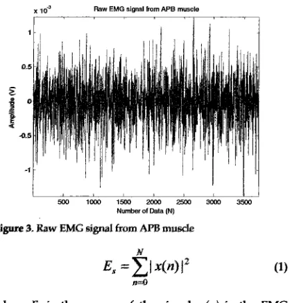
The recorded EMG signals from the muscles, as shown in Figure 3, contain important information about muscle contraction during thumb operation However, these signals can easily be contaminated by external interference such as electrode noise, motion artefacts, power line noise, ambient noise and inherent noise in surrounding electrical and electronic equipment. Therefore, in order to remove the noise, the recorded signals were pre-processed using a band pass filter with a cut-off frequency between 20 and 500Hz [4], [17-191. The strength of the filtered EMG signals that can be observed through signal energy is important for prosthetic thumb control. This energy was computed using Eq. 1 and the example of the signal energy is plotted in Figure 4.
Nor Anrja Jalalud~n, Shahrul Na'lm Sidek and Ahu Uba~dah Shamsudin: Neuro-based Thumb-tip 3
x 10" Raw EMG signal born APB muscle 2.4 Feature Extraction
I 1
After transforming the EMG signals into the form of signal energy, the signals were extracted using the Root Mean Square (RMS) using Eq. 2. This method is used to extract the useful information that is hidden in the EMG signals and remove the unwanted parts and interferences.
(2)
I I I
503 loo0 15W m 2503 3WO 3500
Number of Data (N) where N is the number of EMG data, n is data index and x
is the value of the data F i3. Raw EMG e i g d from All3 musde
where ES is the energy of the signal, x h ) is the EMG signal and
hT
is the rtumber of data.'Ihe signals are later smoothed using the Moving Average
(MA) in Eq. 3 to obtain the enveloped EMG signals.
where k is the size of the moving window, i is data index and xis the value of the data
The amplitudes of the enveloped EMG signals from all the musdes are different between subjects. The
differences need to be unified for better EMG signal classification for the purpose of controlling the prosthetic thumb. One of the techniques used to control these variables is through normalization
The
normalization can be performed by using the max-min normalization technique in Eq. 4 and shown in Figure 4.Figure4. Signal energy from A P B muscle
x-minA
xmm = (new max A -new min A)
+
new min A (4)max A - min A
I
I
---
A P B m C l eI
,.-.-.
---
---
---
A P m u d eI
-p.-
.-,-.
---.-.-.
I
t
I
5""..".""""..""
2
0.6.-.- .---.*
I
-
t....".~'"""""'"
!"..*"
.,.,.---...-....
*J
P
0 . 5 C.-...-.
*...-.
---a- I I - - - -
----
-
-
I--
I
I
-1 5 D w e e
1
30 Degree 45 Degree9.3 7
- - I - - * - - - 0.2
-1
J
-I
0.1 I 1
!
II
I290 400 680 m 1MO 1200
[image:4.596.94.303.81.299.2]Number of Data [N)
Figure 4. Normalized EMG signals of 100 % MVC force at 0,15,30 and 45 degree of thumb configuration for subject 1
[image:4.596.121.500.517.695.2]where Xnorm is the normalized data, X is the data to be learning dataset was trained in the network together with normalize, rnin A is the minimum value in a set of data, the targeted outputs. These datasets were used to compute
max A is the maximum value in a set of data, new max A is the gradient and update the network weights and biases.
the new maximum range and usually set to one and nao The weights of the ANN were adjusted using the LM
min A is the new minimum range and usually set to zero. algorithm provided by the MATLAB Neural Network
2.5 Classification of EMG signals using
Artificial Neural Nehvork (ANN)
The enveloped EMG signals of each m l e have a unique pattern that can be used in s i p 4 dasification The common k x h i q u e for EMG signal h i f i a t i o n is using an Artificial Neural Network (ANN) 1191. In developing the network, the recorded signal was first divided into a training data set and a testing data set. The training dataset from four musde, targeted f o r m rmd targeted angles
that
give a total of 19200 data sets were trained in the network Qe., BOO input datasets from each muscle).
The
type
of networkd
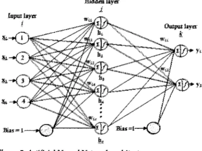
in this work is a feed forwardnetwork with a kvmberg-bbrquardt training a l g o r i h as shown in Figme 5. The designed network wmists of four neurom in the input layer, one
hiaden
layerand
two neurons in the output layer with a s i p i d activationfunction Four neurons at the hput layer, rep-ted as w,
~ 2 , ~ 3 a n d w , a n e ~ E M G s i g n a l s h r o m t h e A B ~ l e , A P B muscle,
FDI
muscleand
FPB
m u . . The yland
y2 notaibn in the output layer reprentthe
targeted thumb-tip force and joint angle. There were two types of activation function used in the system that known as t a n - s i p i d transfer functionand
linear transfer function The tan- s i p i d transfer function that was used to classify the signals intoclasses
was applied in a hidden layerand
the linear transfer function that was US88 to identify and approximatethe relationship between
the
EMG signals, thethumb-tip fore and the joint mgks was applied in h e
[image:5.597.89.296.506.660.2] [image:5.597.319.527.572.686.2]output layer,
Figure 5. Artificial Neural Network architecture
To optimize the generalization, an early stopping method was applied to randomly divide the dataset into 70% learning set, 15% validation set and 15% testing set. The
Toolbox. The algorithm can be represented as follows:
w = w + A w
(5)wherewis~weightvector, Awisthectiffe-between the weight vector, J is the Jacobirm matrix that wntains
the
first derivatives of
the
network error with respect to the weight, is a smle parameter, I is the identity mat& R is h vector of h e refenmce motion, z is a vector of the estimated motion and e is a vector network emors,For the developed network, the choice of the optimal number of hidden neurons used in the hidden layer is based on the evaluation of the ANN performance using Normalized Root Mean Square Error (NRMSE). The best
ANN
architecture is shown by the smallest value ofNRWZ or test error [20]. It should be noted that an insufficient number of neurons could cause the network to be unable to model the complex data, resulting in poor fitting of the modeL Meanwhile excessive neurons wuld
cause the training time to b-me very long, resulting in over fitting of
the
model from the data supplied.Therefore, a series of tests was performed using various numbers of hidden neurons from 10 to 20 for evaluation,
as shown in Figure 6. The number of hidden nodes used in the neural network that gives the smallest test error for force and angle is selected as the optimal number of hidden neurons. In this research five neural networks from five subjects were trained to observe individual responses rather than a combination of all
the
subjects. The optimal numbers of hidden neurons were unique for each subject The selected hidden neurons are 16 neurons, 19 neurons, 15 neurons, 15 neurons and 14 neurons for Subject 1 to Subject 5, respectively.;
0,8002
0,600a +force error
z
0,4000,200 -angle error
0,Oo'J
1011121314151617181920
Number of hidden neurons
Figure 6. ANN simulation result to determine the optimal
number of hidden neurons for subject 1
Nor Anrja Jaialud~n, Shahrul Na'im S~dek and Abu Uba~dah Shamsud~n: Neuro-based Thumb-t~p 5
3. Results and Discussion where x, y and N indicate the measured force by the force sensor, the estimated force from ANN and the total data, The movement of the thumb produces a joint angle and respectively.
force at tiw humb-tip. Therefom, for proper control of
the
prosthetic
thumb
movement,the
relatiomhip between the EMG signals and the joint angh, s well as the tfuunb-tipforce, must be established. This relatiomhip can be
modelled
using ANAl throughthe
clasghtion of EMGsignals at diffemnt joint angles
and
thumb-tip forces. Theperf0nnam-x of the developed newal network can be evaluate8 by applying h d h g data to
the
network. Testing data is another set of enveloped EMG signals thathas
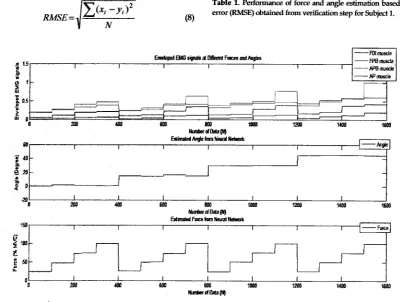
not been seen by the network The outputs from the testing procedure are in the form of % MVC for thumbtip force and degrees for the joint angles, s shown in Figure 7. The patterns ofthe
responses from all five subjects are sim'ir to this m e .B
d
onthe
figure, the neural network has successfully classifkdthe
EMG signals according to the angle and force, Italso has
effectively estimated the joint angles and thumb-tip force6 from the testing data. The response shows thatEMG
amplitude is insredig with the increases in joint anglean8
%hnC,
F u r b o r e , the combinations of envelopedEMG
signals from four muscles are unique for different anglesand
thumb-tip form. The performama ofthe
s t h a t i o n were made based on the RootMean
Square Error (RMSE) obtained fromEq.
8.Table 1. Perfonname of force and angle estimation based on the
[image:6.595.321.532.124.383.2](8) error W E ) obtained from verifbtion step for Subject 1.
Figure 7. Thumb-tip force and joint angles values predicted using neural networks for Subject 1
[image:6.595.107.510.389.691.2]The RMSE is calculated by determining the error between the actual values and the predicted values using the neural network The small errors obtained from the testing step are reflected in Table 1. The table shows that the estimated values are quite close to the actual values. However, there are some errors that are slightly bigger compared the other values due to outliers that occurred at the estimated values and only small portion are affected. The performances of the estimations for all the subjects are similar to this table. Therefore, it can be concluded that the ANN model of the relationship between EMG signals, thumb-tip forces and joint angles have been successfully developed.
The ability of the neural network to classify the signals
and
perform estimations rnakes it suitable to be included in the system that control6 the operation of the prosthetic thumb.The
input to the prmthetic control system is the envelopedEMG
signals from the four muscles. These signals contain information about a particular value of force and joint angle.The information from the signak was extracted using
the
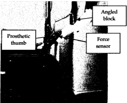
developed neural network and etas the desired values for the prosthetic control. The desired joint angle value was sent to the motor controller to m v e the servomotor by a l&gree step. The servomotor was coupled with
the
[image:7.595.324.530.163.323.2] [image:7.595.94.301.403.570.2]prosthetic h b
and
caused this devise to move towards the angle$ block, as shown in Figure 8.Figure 8. Prosthetic thumb movement toward 450 angle block
The movement of the prosthetic thumb generates force at the thumb-tip. The thumb-tip force was measured using a force sensor that was placed on the flat surface of the angled block. Then, the measured force was compared with the desired force from the ANN. The prosthetic thumb-tip force response is shown in Figure 9. If the measured force is less than the desired force, the controller will send a signal to the motor controller to move the prosthetic thumb in a forward direction by five degrees. This process continues until the error between
the desired force and the measured force has subsided to a minimum value.
I£
the measured force is bigger than the desired force, the prosthetic thumb will send a command to the motor controller to movethe
prosfietic thumb backward by five degrees untilthe
error is very small and steady in that position, as shown in Figurelo.Measured and Desired numbtip Force at 25% MVC (7N)
- Desired +me
7
F i i 9. lMearmrrd and desired h m L ~ t i p force at 25% MVC (7RI')
4. Conclusion
' 3 -
5 30-
g..
0, 25-
0
-
$ 2 0 -
15
'"
"
In this research work, the mapping model between the signals from the AP, FPB, APB and FDI muscles to
the
r'
i
i
j
-
,
r'
I-
I
/+
0 '
thumb-tip forces under four different thumb configurations described by 0,15,30,45 degree bl& is established. The estimated force is obtained from 25%, 50%, 755% and 100% of the MVC. The selected muscles are intrinsic types of muscle and are directly involved in controlling the operation of the thumb. The result shows the efficacy of using the
ANN
model to classify the EMG signals for m e r e n t values of force and thumb angles. Furthermore, the result also shows that theEMG
signals can be used to control a prosthetic thumb with help from a neural netwok0 1 0 2 0 3 0 4 0 5 0 6 0 7 0
NwmerdData(N)
Figure 10. Measured and desired joint angle at 950 angle
Nor Anlja Jalatudin, Shahrul Na'irn Sidek and Abu Ubaidah Sharnsudin: Neuro-based Thumb-ttp 7
Tne authors woulrl liLe to aelrnowledg
the
grant numberEDW
A-12-479-1270 and FRCS 0510-130 for supporting ihis r m c h work[q
PPUM (2009) Laporan Tahunan Pusat Perubatan Universiti Malaya 2909. Kuala Lumpur: Pusat Perubatan Universiti Malaya. 272p[2] Tsledo C, JAja L, h l w z
R,
Vera A, Ramirez A (2009) Upper limb prostheses for amputations above elbow: A review. Pan American Health Care E b g e s (PAHCE), pp. 1WlOS.[3] Chang L Y, h/latsuoka Y (2006) A kinematic thumb model for the ACT
hand.
Proceedings ofthe
2006 IEEE International Conference on Roboticsand
Automation, pp. 1900-1005.
[4] Park W, Kwon S, Lee H, Kim J (2009) Thumb-tip force estimation from sEMG and a muscalmIrektd moclel for real-time finger prosthesis. 2009
IEEE
International Conference on Rehabilitation Robotics, pp. 385-310. [5] Salah M kt, Khalid KN
(20089 Thumb reconstructionby grafting skeletonized amputated phalanges and soft tissue cover
-
A newtechnique:
A case series.Cases Journal, 1: pp. 725- 730.
[6) Cael C (2016) Functional Anatomy: Mugculmkeletal Anatomy, Kinesiology
and
Palpation for Manual Therapists. Pennsylvania: Lippincott Williamsand
wilkins. 452p.[71 Rogers K (2011) Bone and Mus(sIes5tructure, Force and Motion, New York Brittanica Educational Publiihing. 269p.
[8]
So0
Y, Sugi M, Yohi El, Arai T, Nishino h4, Kato R, Nakamura T,Ota
J (2010) Estimation of handgrip force using frequency-band technique during fatiguing muscle contraction J Electromyogr Kinesiol. 20: pp. 888-895.[9] Castelhi C, vnn der Smagt P, Sandhi G, Hirzinger G (20089 Surface EMG for force urntrol sf mechanical hands. 2008 IEEE International Conference on Robotics and Automation pp. 725- 730.
[lo] Harada A, Nakakuki T, Hikita M, Ishii C (2010) Robot finger design for myoelectric prosthetic hand and recognition of finger motions via surface EMG. 2010 IEEE International Conference on Automation and Logistics (ICAL). pp. 273-278.
[ll] Tenore F, Ramos A, Fahmy A, Acharya S, Etienne- Cummings R, Thakor N K (2007) Towards the Control of Individual Fingers of a Prosthetic Hand Using Sudace EMG Signals. Procedhgs of the 29fi International Conference of the IEEE EMBS. pp. 6145- 6148.
[12] Jung K JC, Kim J W, Lee H K, Chung S B, Eom K H (2007) EMG pattern classification using spectral estimation and neural network. SICE Annual Conference. pp. 1108-1111.
[13] Yuan C, Zhu X, Liu G, Lei M (2008) Classification of the surface EMG signal using RQA based representations. 2008 IEEE International Joint Conference on Neural Networks. pp. 21062111. [14] Karimi M, Pourghassem H, Shahgholian G (2011) A
novel prosthetic hand control approach based on genetic algorithm and wavelet transform features. 7a International Colloquium on Signal Processing and its Applications (CSPA). pp. 287-292.
[15] Chu J U, Moon I, Mun M S (2QI96) A Real-Time EMG Pattern Recognition System Based on Linear- Nonlinear Feature Projection for a Multifunction Myoelechic Hand. IEEE Transactions on Biomedical Engineering, 53: pp. 2232 -2239
[16] McKinley M, O'Loughlin V (2011) Human Anatomy. New York: McGraw-Hill Science Engineering. 956p. [17] Konrad P (m5) The ABC of EMG: A Practical
Introduction to kinesiological Electromyography. USA: Noraxon Inc. 60p.
1181 Ibrahim Z, Nagarajan R, Rizon M, Hazry D, Ruslizam D, Azlin C 0 (2008) Electromyography Signal Based For Intelligent Prosthesis Design Proceedii for the 4h International Conference on Biomedical Engineering. pp. 187-190.
[19] Ahsan M, Ibrahirny M I, M a0 0 (2011) Hand motion detection from EMG signals by using ANN based classifier for human computer interaction. 4h International Conference on Modeling, Simulation and Applied Optimization (ICMSAO). pp. 1
-
6.[20] Choi C, Kwon S, Park W, Shin M, Kim J