Pattern Following Bot
Pratik Thakkar*, Ronak Massand*, Sahil Baxi**
*
Electronics Department, Vivekanand Education Society’s Institute of Technology **
Electronics Department, Ramarao Adik Institute of Technology
Abstract-Our idea is to build a pattern following Stinger Bot which follows a specific pattern that is drawn on the computer by a GUI interface by considering various algorithmic factors. It will find its applications in military sting operations and industries where the equipments or the parts need to be dynamically moved.
It uses a ‘Paint’ like GUI on which the user defines a path he wants the robot to follow. This is then broken down using precise algorithms and transmitted wirelessly to the bot. The bot then decodes this information by passing the data through an Intel Atom processor, a serializer which finally maneuvers the motors along the path specified by the user on the GUI interface. The simplicity of the interface hides a labyrinth of contraptions and algorithms- which marks the beauty of this project.
Index Terms- Pattern Following Bot, Intel Atom Processor, Serializer 3.0, Robotics project
I. INTRODUCTION
e are in an age where the application of a robot changes by the minute. A set of movements defined for a robot change with time and situations. Our approach of controlling the path of a robot by just playing around on a virtual chalk board environment aims at raising the intuition behind controlling these expensive and complicated machineries. There are number of subsystems that must be designed to fit together into an appropriate package suitable carrying out the task.
The primary purpose of this project is to make our autonomous vehicles easy to manipulate using a GUI interface. Our setup also provides for a multifunctional reprogrammable general purpose robot which can maintain its internal system and can be redesigned for handling situational tasks.
The Project has two key parts - A GUI interface on a PC.
- A receiver and an Intel Atom Processor on the robot.
1. Program on the computer
This is a program that is executed in the normal PC. It runs the application file on the PC. A paint like GUI opens where the user can define the path by drawing it on the interface. This user specified path is sampled and sent on an IP address. This IP address is the same as that of the Micro-processor Board.
2. Receiver and Executor on the Robot
The sampled data from the host PC is received here. This sampled data is processed on the board and then given to the motor driver. It sends the control signals to the motor driver which in turn controls the motor movements by actuating them at the right duration making the bot follow the same path specified by the user.
3. Software Details
The programs and interfaces for this project have been written in C# in a .NET framework. The simulation and the deploying software used is Microsoft Visual Studio 2008.
II. DESCRIPTION
We have developed a paint like GUI on which user draws any random path which one wants the bot to follow. An Algorithm at the transmitter end extracts angles by sampling the path and creating a table of angles to be transmitted over the Wifi network. This is then received by an application on Intel Atom receiver which translates the angles to motor movement and navigates the bot
A. Design
The Transmitter side
1. Paint GUI
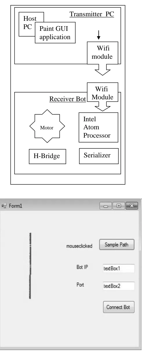
This is the GUI on which the path to be followed is drawn. The GUI contains an IP text field and the port number of the receiver, which allows us to configure the wireless connection. The path is sampled first on the transmitter side and then transmitted through the Wifi module. This takes place once all the inputs are mentioned and the user clicks on the sample button on the interface.
2. Wifi Transmitter
The sampled path along with the information about the sampled points is then sent through the Wifi transmitter and received on the other side through a Wifi receiver on the stinger bot.
Figure 1: Block diagram of system
Figure 2.Dialogue box on Transmitter Side
The Receiver side:
1. Wifi Reciever
It is a normal wireless receiver used at the receiving end since the board doesn’t have a inbuilt Wi-Fi receiver. It receives the sampled path signals. This is processed by the atom processor and converted at the machine level language.
2. Intel Atom Processor
This is the brain of the complete system. Intel Atom Processor computes the distance between the sampled points and also calculates the angles that the bot needs to take by the algorithm explained later. This processor has a Windows Embedded 7 installed on it and it also provides all the necessary networking services required to support the Wifi receiver. The processor then sends the angles and the distances calculated to the serializer. It interacts with the serializer and in turn actuates the motors.
3. Serializer
Serializer is the component which converts all the calculated angles and distances into machine language that the bot can understand in order to control the motors. It is an interfacing device between the processor and the bot which acts like a translator so that the bot understands the commands and hence the motors will rotate accordingly. It is used in the .NET framework.
4. H Bridge
[image:2.612.362.528.427.538.2]H Bridge is a circuit which helps rotate the motors in both the directions. This helps in taking steep turns with unusual angles.
Figure 3: H-Bridge
B. ALGORITHMS
1. Distance
Extrapolating distance is a simple matter of calculating the length between each successive point. The longer the distance between successive points, the faster the car should be going. Calculating this distance is a trivial matter of utilizing Pythagorean's Theorem: Distance = √[(x2-x1)2+(y2-y1)2]
2. Angles
Extrapolating the direction from the points requires a bit more math and a lot more creativity. What is important here is not the absolute angles derived from the points, but the angle compensation needed by the Bot with respect to its current position in order to correctly follow the user path. The desired
Transmitter PC
Host
PC Paint GUI
application
Wifi
module
Receiver Bot
Wifi
Module
Intel
Atom
Processor
Serializer
H-Bridge
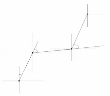
final output is the angle that the Bot's wheels must turn in order to keep following the path. The basic math behind deriving absolute angles between points is simple trigonometry. What we desire in the end is the change in the angle from the previous value, illustrated in figure.
Figure 4: Figure showing sampled points
The lines that connect each point have been elongated to illustrate the placement of the desired angle. This angle can be easily calculated by first calculating the absolute angle from the line connecting the current point and the previous point with respect to the Y-axis. Then the calculated absolute angle formed by the previous line must be subtracted from this current angle.
Figure 5: Figure describing angle calculation
Embedded within the problem of finding the turn angle lays the problem of detecting when the car needs to move backwards. To deal with this problem of different forms of path that can be drawn we decided to form an exhaustive case structure which would handle all sorts of possible movement combinations. Any user drawn path either leads to increase or decrease or none in X and Y directions.
[image:3.612.79.256.138.293.2]According to this there can be eight exhaustive cases:
Figure 6: Eight cases for angle calculation
We mathematically calculated the angle compensation for all these cases and we mapped the X and Y co-ordinates obtained from our curve in these eight cases. The angles so calculated are sent to the bot.
Case 1
According to the cases listed above let us take an example of the first case where ∆x=0 and ∆y>0.This means there is no movement of the bot in the X axis but the bot will turn 90 degrees and move along the Y axis in the positive direction.
Case 2
The second case ∆x=0 and ∆y<0 denotes there is no movement along the x axis but the bot will turn 90 degrees in the negative Y axis and move along it.
Case 3
The third case, which says ∆x>0 and ∆y=0 denotes there is no movement of the bot along the Y axis but the bot will turn in the positive X axis and move along it.
Case 4
The fourth case, which says ∆x<0 and ∆y=0 shows absence of movement in the Y direction but the bot will turn and move along the negative X axis.
Case 5
The fifth case, which says ∆x>0 and ∆y>0 denotes the movement of the bot in the top right direction i.e. along the positive X axis and the positive Y axis as x2 and y2 are greater than x1 and y1 respectively.
Case 6
The sixth case where ∆x>0 and ∆y<0 shows the movement of the bot along the positive X axis and the negative Y axis i.e. bottom right direction.
Case 7
The seventh case ∆x<0 and ∆y>0 signifies the movement of the bot along the negative X axis and the positive Y axis i.e. top left direction.
Case 8
[image:3.612.67.268.408.546.2]III. HARDWARE AND SOFTWARE DETAILS
A. Hardware Details
The details of all the hardware equipments we have used are specified below.
1. AIMB-212(Intel Atom N450/D510) Processor:
We used an Intel Atom processor instead of using an AVR microcontroller because we made provisions to integrate real time video to assist the stinger bot.
The Intel Atom Processor is a 1.66 Ghz processor with 6 serial ports for interfacing. It supports USB 2.0.The Processor does all the mathematical distance and angle calculations at the run time when it receives the signal from the WiFi receiver. The calculated answer is then given to the serializer.
The specifications of Intel Atom are as follows:
Standard SBC functions
CPU: Intel® Atom™ processor N450/D510 1.66 GHz BIOS: Award 16 Mbit SPI
Chipset: ICH8M
System Memory: Up to 2 GB; 200-pin SODIMM x 1, Single-channel 667 MHz DDR2
SATA2 Interface: Two onboard Serial ATA connectors and data transfers up to 300 MB/s
CF interface: Supports compact flash Type II
Serial ports: Six serial ports, COM1, COM3, COM4, COM5 and COM6 are RS-232; COM2 is RS-232/
422/485
Keyboard/mouse connector: Supports one standard PS/2 keyboard, one standard PS/2 mouse(Onboard 6pin wafer box)
Watchdog timer: 1~255 level timer intervals
USB 2.0: Supports up to eight USB 2.0 ports, four exter-nal ports and four onboard pin headers
GPIO: 8-bit general purpose Input/Output
Graphic Interface
Controller: Embedded Gen3.5+ GFX Core, 200/400 MHz render clock frequency for
N450/D510
Display memory: Dynamically shared system memory up to 224 MB
VGA: Supports resolution up to SXGA 1400 x 1050 pixels, 32bits, 60Hz refresh rate
for Atom N450, supports resolutions up to 2048 x 1536 @ 60 Hz for Atom D510
LVDS interface: Supports 18-bit single channel and up to WXGA 1366 x 768
LVDS port: Supports Single LVDS connector Ethernet Interface
LAN1: 10/100/1000 Mbps GbE LAN Intel 82567V LAN2: 10/100/1000 Mbps GbE LAN Intel 82583V
Mechanical and Environmental
Dimensions (L x W): 170 x 170 mm Power supply voltage: 12 V
Power requirements: AIMB-212N sku +12 V @ 1.78 AAIMB-212D sku +12 V @ 1.99
A(Maximum measured current values with system under maximum load)
Operating temperature: 0 ~ 60° C Weight: 0.365 kg (weight of board)
2. Serializer
The Serializer 3.0 Robot Controller provides a ready-to-use solution to interface the Microsoft™ .NET framework, or C++ applications to the most common robotic hardware. The pluggable interface modules include RS232 or USB. The TTL serial port is built into the base serializer board. XBee, USB, and RS-232 modules are purchased separately. Through the serializer it is very easy to interface DC motors, servos, analog sensors, I2C slave devices, single and quadrature encoders, switches/relays, and other devices to the .NET framework and/or C++ applications.
B. Software Details
The Software design phase consisted of the following stages: 1. PAINT GUI Application on C#
A GUI was developed in C# for the Paint GUI. It essentially generates a field area where the user can draw the path. The application then extracts the co-ordinates of various sampled pixels and converts co-ordinate information into corresponding angle and distance information to be transmitted. On clicking the Start button, these values are written into a file.
2. Socket Programming over Wifi
The IP address of the receiver is obtained. After establishing the communication over a port, the transmitter sends the angles and distances in the stored file as bytes. Once all the data is transmitted, the communication is terminated using a special character.
3. Control signals for BOT
Visual Studio 2008
Visual Studio 2008 is focused on development of Windows Vista, 2007 Office system, and Web applications. For visual design, a new Windows Presentation Foundation visual designer and a new HTML/CSS editor influenced by Microsoft Expression Web are included. J# is not included. Visual Studio 2008 requires .NET 3.5 Framework and by default configures compiled assemblies to run on .NET Framework 3.5, but it also supports multi-targeting which lets the developers choose which version of the .NET Framework (out of 2.0, 3.0, 3.5, Silverlight CoreCLR or .NET Compact Framework) the assembly runs on.
IV. FUTURE WORK
A lot of structural and functional changes can be made to our prototype model to fit this robot into various commercial slots. The Angle calculations can be optimized using better and much more complex algorithms resulting in better turn angles and precise movement. We aim to add obstacle detection to the interface by scanning the work surface to make this a versatile automated machine. There has also been a direction of thought given to creating a real time path trace which would mean superimposing a real time image from an onboard camera as the background of the Paint interface. This would increase the intuition with which the user can control the bot. The power of such a device can be improved two folds by using its windows OS and providing control signals for the robot over the internet. A high speed Atom processor could also mean this robot can act as a host machine to control and coordinate with multiple sub-machines and organize an entire colony of intelligent sub-machines.
REFERENCES
[1] Atmel AVR Microcontroller Primer,.Steven F. Barrett Daniel J. Pack [2] The design of Everyday things,Donald Norman
[3] Serial Port Complete Second Edition,Jan Axelson
AUTHORS
First Author – Pratik Thakkar, Bachelor of Engineering,
Vivekanand Education Society’s Institute of Technology and [email protected]
Second Author – Ronak Massand, Bachelor of Engineering,
Vivekanand Education Society’s Institute of Technology and [email protected]
Third Author – Sahil Baxi, Bachelor of Engineering,