IMPLEMENTATION OF INTELLIGENT CONTROL
STRATEGIES ON CURRENT RIPPLE REDUCTION AND
HARMONIC ANALYSIS AT THE CONVERTER
SIDE OF THE INDUSTRIAL INVERTERS
AND TRADEOFF ANALYSIS
1R.SAGAYARAJ, 2 Dr. S.THANGAVEL
1
Research Scholar, Department of Electrical & Electronics Engineering,
Anna University, Chennai, Tamil Nadu, India
2
Professor & Head, Department of Electrical & Electronics Engineering,
K.S.R. College of Technology, Tiruchengode, Tamil Nadu, India
E-mail: [email protected] , [email protected]
ABSTRACT
This paper presents a trade-off analysis among different intelligent control based resistance emulation techniques. Resistance emulation, which is the consequence of the current ripple reduction and harmonic reduction, is developed with intelligent control on different Pulse Width Modulation (PWM) techniques. In industrial drives, the harmonic reduction has been carried out using different PWM techniques in the inverter side of the drives, but this paper deals the harmonic current ripple reduction in the converter side of the electrical drives. The three-phase induction motor is connected as load to the boost converter for this analysis. Traditional PI controller based active resistance emulation is compared with the Fuzzy Logic Controller (FLC) and ANFIS controller based emulator. The analysis that would suggest the trade-off on the performance of each of this technique gives guidelines to select on which technique to be adopted at what situation. MATLAB / Simulink based simulation is carried out and the results are tabulated for the comparison purposes. The parameter for comparison is the current ripples and the Total Harmonic Distortion (THD). The simulation results show the effectiveness of the proposed method.
Keywords: Adaptive Neuro-Fuzzy Inference System (ANFIS), Average Current Mode (ACM), Fuzzy Logic Controller (FLC), Pulse Width Modulation (PWM), Total Harmonic Distortion (THD)
1. INTRODUCTION
Modern computers, communication and electronic systems get their “Life Blood” from power electronics. But unfortunately power electronic systems are subjected to low power factor, harmonic distortions on supply as well in load circuits. However these bottlenecks can be overcome by using “Intelligent Controlled Power Electronics Converters” which uses fuzzy logic, artificial intelligence, ANFIS, swarm intelligence for generating control signals and mitigating current harmonics. Broadly AI based techniques will play significant role in power electronics and motor drives. Fuzzy Logic control, ANFIS control will possibly provide the best robust performance in non-linear feedback systems such as in thermal plant, nuclear generating stations, solid state drives and so on. Hence an intelligent controlled energy efficient power electronic system plays a vital role
against the thrust areas in research, which is addressed in this paper.
devices along with the PWM techniques. This active resistance emulation was basically implemented using the traditional PI controller [3].
This paper introduces the ANFIS controller to be implemented for resistance emulation and compared for the performance with the PI controller. These intelligent techniques would adopt the model of the resistance emulation and would help the control to be done faster and adaptable. These decision-making algorithms are developed by the use of the expert knowledge gathered from the history of experiments. The output from the PI controller is taken as the knowledge and is transferred to the FLC and ANFIS model and the performance is analyzed. The parameters of analysis are taken as the Total Harmonic Distortion (THD), current ripple, peak overshoot and settling time.
The comparisons of these parameters are taken and are concluded using Power Factor Correction (PFC) device, which is the boost rectifier with third harmonic elimination using the current injecting reactors. The active PFCs are the combination technique involved in the PWM generation [4]. This paper takes up the power factor correction in the single phase among the three phases and can be extended to each phase of the three-phase supply. The adaptability of these intelligent techniques would make the control very robust and the design overheads being neglected.
The paper is organized as follows. A brief review about the work done by various authors was presented in the introductory section. Section II gives a brief overview of the resistance emulation technique. Development of the fuzzy logic and ANFIS controller is presented in section III, whereas the design of the boost converter is presented in section IV. Controller for the proposed method is depicted in section V followed by the simulation results and discussions in section VI. The conclusions is presented in the last section VII followed by the references.
2. RESISTANCE EMULATION
Resistive emulation is defined as the process of attaining unity power factor in the AC supply side by emulating the rest of the circuit to be resistive [5]. Thus, the input voltage across the rectifier and input current to the rectifier are
in-phase with each other at every in-phase. The resistance emulation technique boils down to shaping the input current, supply being of constant voltage. The Average Current Mode (ACM) method is a successful method implemented for emulating resistance by the use of power electronic devices. The boost converters are usually used for PFC in many Switched Mode Power Supply (SMPS) applications and the same has been taken up in this paper.
The boost converters are natural harmonic reduction devices, as the capacitor in their load side would eliminate the second order harmonics in the supply side [6]. So, only the odd harmonics are to be taken up seriously and the PWM techniques are developed towards reducing or eliminating the odd harmonics. The basic design including the PI controller is developed and is compared with the FLC and ANFIS controller for this purpose. The current is usually sensed and compared with the reference current for generating the switching sequence. The switching sequence that is developed for the switches depends on the variation between these two currents [7].
The current comparison is made with the up-slope of the inductor current and the level of the reference current. Because of this, a spike is created at each switching of the switches. A sub-harmonic oscillation is produced at a duty cycle greater than 0.5 in this peak current control method [19]. The Average Current control Mode (ACM) would track the current program with higher accuracy. The immunity to noise is more robust in the ACM method. This can be used to sense and control the current in any circuit branch.
3. FUZZY LOGIC CONTROLLER & ANFIS CONTROLLER
Fuzzy Logic Controller (FLC) is more advantageous than the traditional controller like PI and PID controller as it is linear and simple. The simplicity is that the development of the FLC is a possibility, even without the knowledge of the system under study. The FLC based on the fuzzy rules using the membership functions makes a control system look easy as compared to the mathematical model for a control system.
knowledge of the ACM method’s input and output parameters applied on the boost converter under study. The settling time and the peak overshoot are tuned to more desirable values by the use of FLC. In this paper, the fuzzy logic control is taken for comparison, because the fuzzy logic controller acts like the inference engine that would follow the PI controller.
The peak overshoot is completely brought down while we use FLC. But, after reconsidering the membership functions and the inference engine, we would develop a better control than the PI controller. This improved controller is trained into the ANFIS controller. The controller would act dynamically as it is trained with the neural network.
The Fuzzy membership functions are trained with the Neural Network nodes to have the control technique inherited into the ANFIS controller. ANFIS gets trained with the membership functions and the fuzzy rules in its model. The learned ANFIS system is a model that would be more adoptable to any kind of situations than the FLC. So, for more dynamic environment, the ANFIS system would act very efficiently.
4. BOOST CONVERTER DESIGN
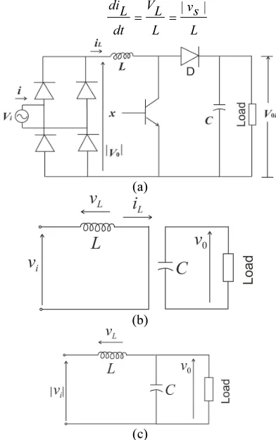
[image:3.595.307.503.292.604.2]Boost converter based PFC has been a trend as it has the design that would eliminate the second order harmonics in the supply side. The reduction of harmonics and the voltage ripple is taken care by the ACM method. This circuit is obtained by combining the uncontrolled rectifier with the boost converter topology which is then connected to the Voltage Source inverter (VSI) with the three phase induction motor as given in the Figure 1.
The Induction motor is made to work without any control technique, thus running at its rated speed. The specification of the induction motor considered for the research study is 5.4 HP, 400V, 1430 rpm, 50 Hz, 4 poles one. As the motor is a 400 V three phase induction motor, in order to limit the starting current, we should have used the starter in order to get rid of the starting current dynamics, but the inductor in the boost converter would serve the purpose of the smooth starting of the induction motor, hence starter can be avoided. The schematic of the converter with the induction motor is as given in Fig. 1.
Figure 1: 1-φ Boost Rectifier with he 3-φ
Electric Drive System
The boost converter is designed for the following design criteria. When the transistor switches ON, the equation of the current iL(t) is given by the following equation (1) as
L s v
L L V
dt L
di | |
=
= (1)
(a)
(b)
(c)
Figure 2 : Single-Phase Boost Rectifier for the Electric Drive System: (A) Power Circuit and Equivalent Circuit
for Transistor T in (B) On-State And (C) Off-State
Due to the fact that |vs| > 0, the ON state of transistor T always produces an increase in the inductance current iL. The design parameters for the design of the boost rectifier is given in equation (2) as
) ( 5 . 8
2 0 2 0
0 0
min min
2
approx mF
L hld
V
V
t
P
C
=
−
=
(2)
C0 = Output capacitance,
P0 = Output power of the converter 4 KW,
thld = Hold up time, normally 20 ms,
V0min = Minimum value of the output regulated voltage (400 V DC),
V0Lmin = Range of input voltage (230V AC).
The value of the boost inductor affects many other design parameters. Most of the current that flows through this inductor is at low frequency. This is particularly true at the lowest input voltage where the input current is the highest. Normally, the acceptable level of ripple current is between 10 and 20 %. For a switching frequency of 100 kHz, the following formula will produce acceptable results.
La = 3000 / Po mH
La = 300 / 250 = 1mH (approx.)
The capacitor that is designed from the boost converter configuration will eliminate the second harmonic in the first hand. The Fourier analysis tells that the amount of the second harmonics present is about 0.02 % whereas the third harmonic is about 63.93 %. Considerable attention is given towards suppressing the third and successive odd harmonics in our proposed system, which is one of the contributions of the research work.
5. PROPOSED METHOD
The average current mode model has been an important which has been extensively used in most of the SMPS design platform for the power factor correction purposes. The modeling of the resistance emulation technique that is based on the average current mode model using fuzzy logic and neuro-fuzzy systems is designed and the performance of this method is analyzed with and without the three phase induction motor. The Fuzzy logic and the ANFIS toolbox from Matlab / Simulink are used for the modeling and implementation of these analyses.
The boost converter is loaded with the three-phase induction motor for the analysis that would also include the harmonics due to the induction motor introduced to the source .This harmonics also must be taken care of by the boost converter’s resistance emulation technique. This paper deals with the comparison of THD and
current ripple introduced to the source side of the boost converter both with the drive and without the electric drive and how much the resistance emulation ACM technique reduces the THD and current ripple. Our proposed design uses the following fuzzy parameters,
• Number of Membership Function (MF) : 9, • Type of MF : Triangular & Trapezoidal, • Type of fuzzy system : Takagi Sugeno, • Fuzzification method : Normalization, • De-fuzzification method : Centroid and the
following neuro–fuzzy parameters are as below,
• Number of Epoches : 100,
• Function used for learning : Sigmoidal, • Tolerance : 0.0001,
• Number of hidden layers : 2,
• Algorithm used for learning: Back propagation
network.
6.
SIMULATION RESULTS & DISCUSSIONSOnce the design has been over, the Simulink model of the proposed design is developed in the MATLAB / SIMULINK environment. The simulation is run for a certain amount of time for the above designed boost converter with the parameters mentioned in the previous section. The resistance emulation using the average current model of the PWM generation is developed with the sampling frequency of and switching frequency of in the above said boost converter. The boost converter for the THD reduction in two modes is taken and analyzed. One is static and the other is dynamic mode. The first mode is with constant load and the second one is with dynamic change in the load.
Figure. 3 : Voltage Response from the Converter without ACM Applied
The initial peak overshoot is evident in the transfer average current mode model that can be reduced in the fuzzy logic implementation, that being the advantages of the Fuzzy Logic Controller (FLC). The PI and the PID controller also reduce the peak overshoot in the boost converter. But, the major advantage for the FLC is the settling time, which also gets reduced. As the implementation is the transfer function based we have modeled that into the FLC and the ANFIS systems. The FLC system showed fast settling times, but when considered for dynamic performance; it fails, whereas, ANFIS system exhibited superior dynamic performances.
The THD and the Current ripple calculated from each method have been tabulated in Table 1. From the table, we can infer that the current ripple can be reduced efficiently by the reconfiguration of the fuzzy inference engine and the ANFIS. The Takagi Sugeno model was used for both the FLC and ANFIS. The waveform for the voltage and current response for dynamic change in load without ACM controller is shown in Figs. 2 & 3. The initial peak overshoot for voltage and current response in the PI controller based ACM would affect the life of the reactive elements in the SMPS. The AC side voltage and current response without ACM controller is given in Fig. 4.
Figure 4 : Current Response from T\the Converter
without ACM Controller Applied
Figure 5 : AC Side Voltage and Current Response
without ACM Controller
[image:5.595.92.321.103.331.2] [image:5.595.308.537.362.555.2]
Figure 6 : Output Current Response with PI
based ACM Controller
Figure 7 : AC Side Voltage and Current Response with
PI Based ACM Controller
In Fig. 7, we could see that the voltage and the current in the source side are in phase and the dynamics of the current is reduced to a greater extent. The input supply voltage and current waveform that is in phase with each other for the ANFIS controller is shown as below in Fig. 8.
Figure 8 : AC Side Voltage and Current Response with
FLC Based ACM Controller
Figure 9 : AC Side Voltage and Current Response with
Figure 10 : Output Voltage Response with FLC based
ACM Controller
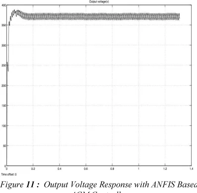
The current and the voltage waveforms are in phase with each other in the supply side as observed from Figs. 8 and 9. It can be concluded that the ANFIS controller has been a good power factor controller than the PI controller from the simulation results. The dynamic performance of the ANFIS controller has been superior than the PI controller based ACM. It can be inferred that the ANFIS controller has high stability through current ripple waveforms as shown in Fig. 5. The current ripple has reduced from 4.28 to 4.16 % when compare to PI and ANFIS controller.
Figure 11 : Output Voltage Response with ANFIS Based
ACM Controller
Table 1: Experimental Results for ACM and ANFIS
Controller
Control
Technique THD in %
Current Ripple in (% of rated current)
Without ACM 63.93 % 30 %
ACM with PI 4.93 % 4.28 %
FLC 2.9 % 4.17 %
ANFIS 2.8 % 4.16 %
7. CONCLUSIONS
In this paper, the resistance emulation model is developed using ACM, ACM trained FLC and ANFIS controllers. The PI controller losses credibility because of the higher peak overshoots. Simulink model is developed in the Matlab environment, simulations are performed & the results are observed. Performance evaluation of the developed controller along with the simulation results concludes that ANFIS controller exhibits superior performance on both transient and dynamic situations. FLC acts only as an inference engine with reduced peak overshoot, however under dynamic conditions only the trained controller like ANFIS would take seat.
As a future enhancement the difficulty in the implementation of the hardware has to be eliminated, by developing an Application Specific Integrated Circuit (ASIC) design on the Field Programmable Array (FPGA) for the ANFIS controller and can be suggested as a future Integrated Circuit (IC).
The merit that is introduced in this method is that the reduction of the lower order harmonics is automatic and doesn’t require any mathematical model. The ANFIS method would introduce the linearity in the non linear nature of the control in the controllers.
The demerits of this implementation are the realization of hardware is difficult and need an ASIC for ANFIS controller.
REFERENCES:
[1] Carbone, R., Corsonello, R., “A new passive power factor corrector for single phase diode rectifier”, IEEE Power Electronic Specialist Conference (PESC’04), Jun. 2004, Aachen, Germany.
[image:7.595.88.298.105.324.2] [image:7.595.89.288.497.692.2]
[3] Garcia, O., Cobos, J.A., Prieto, R., Alou, P., Uceda, J., “Single Phase power factor correction : A survey,” IEEE Trans. Power Electron., vol. 18, no. 3, pp. 749-755, May 2003.
[4] Salmon, J.C., “Reliable 3-Phase PWM boost rectifier operated 1-phase and 3-phase AC supplies and using either single or split DC rail voltage output”, APEC’- 95, pp. 473-9. [5] Carbone, R., and Scappatura, A., “A
high-power PWM adjustable speed drive with low current harmonics,” ISIE-IEEE 2005.
[6] Singh, B., Singh, B.N., Chandra, A., Al-Haddad, K., Pandey, A., Kothari, D.P., “A review of single-phase improved power quality AC-DC converters,” IEEE Trans. Ind. Electron., vol. 50, no. 5, pp. 962-981, Oct. 2003.
[7] Hsu, S., Brown, A., Rensink, L., Middlebrook, R.D., “Modelling and analysis of switching DC-to-DC converters in constant frequency current programmed Mode,” IEEE PESC Proceedings, 1979.
[8] Bird, B.M., Marsh, J.F., Mchellan, P.R., “Harmonic reduction in multiplex converter by triple-frequency current injection”, Proc. IEE, vol. 116, no. 10, Oct. 1969, pp. 1730-1734. [9] Ametani, A., et al., “Generalized method of
harmonic reduction in AC-DC converter by harmonic current injection”, Proc. IEE, vol. 119, pp. 857-864, Jul. 1972.
[10]Carbone, R., Corsonello, P., Fantauzzi, M., Scappatura, A., “Power factor correction in single-phase rectifiers: a performance analysis of passive and line-frequency-commutated active techniques”, Third IASTED Int. Conf. on Power and Energy systems, Europe, Sept. 3-5, 2003, Marbella, Spain.
[11]Carbone, R., Scappatura, A., “A high efficiency passive power factor corrector for single phase bridge diode rectifiers”, IEEE power electronic specialist conference (PESC’04), Jun. 04, Aachen, Germany. [12]Dragan Maksimovic, Yungtaek Jang and
Robert W Erickson, “Non-linear carrier control for high-power-factor boost rectifiers” IEEE Transactions on Power Electronics, vol. 11, no. 4, 1996.
[13]Qian, J., and Lee, F.C., “A high efficient single stage single switch high power factor AC / DC converter with universal input,” IEEE Trans. Power Electron, vol. 13, no. 4, pp. 699-705, Jul.1998.
[14]Qian, J., Zhao, Q., and Lee, F.C., “Single-stage single-switch power factor correction AC / DC
converters with DC bus voltage feedback for universal line applications,” IEEE Trans. Power Electron, vol.13, no.6, pp.1079-1098, Nov.1998.
[15]Qiao, C., Smedley, K.M., “A topology survey of single–stage power factor corrector with a boost type input current–shapes,” IEEE Trans. Power Electron., vol. 16, no. 3, pp. 360-368, May 2011.
[16]Chow, M.H.L., Lee, Y.S., and Tse, C.K., “Single-stage single-switch isolated PFC regulator with unity power factor, fast transient response and low voltage stress,” IEEE Trans. Power Electron., vol. 15, no. 1, pp. 156-163. [17]Zhao, Q., and Lee, F.C., “High efficiency, high
step-up DC-DC converters,” IEEE Trans. Power Electronics, vol. 18, no. 1, pp. 65-73, Jan. 2003.
[18]Jovanovic, M.M., Jang, Y., “State-of-the-art, single phase, active power-factor correction techniques for high-power applications-An overview”, IEEE Trans. Ind. Electronics, vol. 52, no. 3, pp. 701-708, Jun. 2005.
[19]Middlebrook, R.D., “Topics in Multiple –loop Regulators and Current –mode programming”, IEEE PESC Proceedings, Jun. 1985.