USING LDP FASTREROUTE VERSUS LDPORSVP IN AN
MPLS CORE BACKBONE FOR CONVERGENCE
ENHANCEMENT
1
ALA ABDELALI , 2DRISS EL OUADGHIRI, 3 MOHAMED ESSAAIDI
1 Phd student., Department of Electrical Engineering, Abdelmalek Essaadi University , Tetuan 2Assoc. Prof., Science Faculty, Moulay Ismail University, Meknes
3 Prof., Department of Electrical Engineering, Abdelmalek Essaadi University , Tetuan
E-mail: [email protected], [email protected], [email protected]
ABSTRACT
MPLS/VPN backbones are widely used today by various operators and private companies in the world, high to medium-sized, either use an operator or build their own MPLS/VPN backbone. Real time applications like voice and video are more and more integrated to end user applications, making them ever more time sensitive. Operators are offering services like hosting companies voice platforms, voip call centers, iptv ..etc. All these aspects make the convergence time inside a backbone a challenge for service providers. However, the global convergence time is an assembly of several factors including: link or node failure detection, IGP failure detection, LSP Generation, SPT Computation, RIB update, local FIB creation and distribution ...updates signaling...etc., a lot of approaches can be used to minimize the convergence time, our approach consist on enhancements and optimization in control and forwarding plane, the scope of our work is the core backbone, however a lot of things can also be made at the access. In this article we especially focuses on stressing and comparing two methods: “LDP over RSVP in the core P routers” and “ LDP Fastreroute in the core P routers”. Beyond the “state of the art” and implementation of both protocols, we describe in detail our design considerations, impact of faults and test results, the aim of the study is to give an accurate idea of gains and drawbacks of each method and which one more fits an operator infrastructure. We consider this work as a contribution to the global research on the “network convergence item”, it more deals with the state of the art, and features interoperability. A continuation of this work is using same approach while modeling new protocol concepts holding intrinsically the convergence as a constraint.
Keywords: Fast-convergence ( FC), Resource Reservation Protocol (RSVP), Label Distribution Protocol (LDP),Virtual Private Network (VPN), Loop Free Alternate (LFA), Next Hop Label Forwarding Entry (NHLFE), Intermediate System to Intermediate System ( IS-IS), Label Switched Path (LSP), Lost of Signal Detection (LOSD), Multiprotocol Label Switching (MPLS), Protocol Independent Convergence (PIC), Route Distinguisher (RD), Routing table manager (RTM), Provider edge route (PE), bidirectional failure detection (BFD), Provider Router (P), Label Switch Router (LSR).
1. INTRODUCTION
The convergence time reflects the time required by a network to react to the failure of a link or a router itself. When all nodes (routers) have updated their respective routing and forwarding databases, we can say the network has converged. We delimited the perimeter of our study to a
stay under sub-second and consistent in both directions: [core to PE], [PE to core]. From customer point of view: the overall [end-to-end] convergence should stay under 1 sec (no impact on most time sensitive applications).
2. LDPoRSVP
The ldp over rsvp principle can be illustrated in the Fig.1:
Figure 1. LDP over RSVP principle
Only core routers P1, P2 and P3 are enabling RSVP TE and ldp, however they are configured to prefer rsvp tunnels to ldp one’s. The edge routers PE1 end PE2 are enabling only LDP with P1 and P3. PE1 end PE2 are VPN and use MP-iBGP to signal vpn labels.
2.1. Control Plan Establishment:
Let us consider PE2_FEC representing prefixes coming from CE2.
• Establish RSVP tunnel-1-3 from P1 to P3, the label distributed to P2 from P3 is LR2, and the label distributed from P2 to P1 is LR1
• Establish a targeted ldp session between P1 and P3
• Enable IGP shortcut on P1, the egress path for PE2_FEC will be the tunnel-1-3.
• PE2_FEC triggers the establishment of LSP on PE2, and the label mapping message will be sent to P3, let us consider this label is L2.
• After P3 receives the label mapping message, it forwards that message to P1
through the targeted LDP session, let us consider this label is Lx
• P1 receives the label mapping message, and finds out that the egress fo the route is tunnel-1-3.Then the LSP from PE1 to PE2 is transmitted I RSVP TE. The external label is LR1.
• P1 continues to send Label mapping message to PE1, the label is L1.
• PE1 generates Ingress
• MP-BGP sends private network route of CE2 from PE2 to PE1, the label of private network is Lb.
At this stage the establishment of LSP between PE1 and PE2 is complete. This LSP traverses the RSVP TE area ( P1 ~~ P3).
2.2.Forwarding Plane Process
We describe here the forwarding process of data from CE1 to CE2, if needed do the symmetrical reasoning regarding flows from CE2 to CE1:
• After PE1 receives packets from CE1, it tags the BGP label Lb of private network and then it tags LDP label L1 of the provider network
• (Lb,L1) label of PE1 is received on P1, replace L1 with Lx (the label sent to P1 through the targeted ldp session, and then tag tunnel label LR1 of RSVP TE, the label of packet becomes (Lb,Lx,Lr1).
• From P2 to P3, with the RSVP TE
transparently transmitting packets, the LR1 is replaced by LR2,
that is, the packets received by P3 are tagged with the following labels (Lb,Lx,LR2)
• Upon arriving P3, the LR2 is first stripped and then comes out Lx, and the label of LDP wich is replaced by L2.The packet is then sent to PE2 and the label becomes (Lb,L2)
• After the packet reaches PE2, L2 is first stripped and then the Lb. After that, the packet is sent to CE2
IP lb
PE
CE
P1 P2 P3 PE
CE IP lb Lx
IP lb
IP lb Lx
LDP Label:(Lx) on tldp
I
I
LDP LDP
RSVP Label
LR1
LDP Label L1
RSVP Label
LR2
LDP Label L2 L b
2.3. LSP Protection , One To One Backup Method
[image:3.612.337.543.95.359.2]Each P creates a detour (tunnel) for each LSP, the detour will play the rôle of a protecting LSP :
Figure 2. LDP over RSVP backup method
If the router P2 fails, P1 switches received traffic from PE1, along the detour tunnel [P1,P5] using the label received when P1 created the detour. The detour is calculated based on the shortest IGP path from P1 to the router terminating the protected LSP, let us say PE2. In this case the protecting LSP will avoid the failed router P2 (node protection). At no point does the depth of the label stack increases as a consequence of taking the detour.
While P1 is using the detour, traffic will take the path [PE1 - P1 - P5 - P6 - P7 - PE2 ].
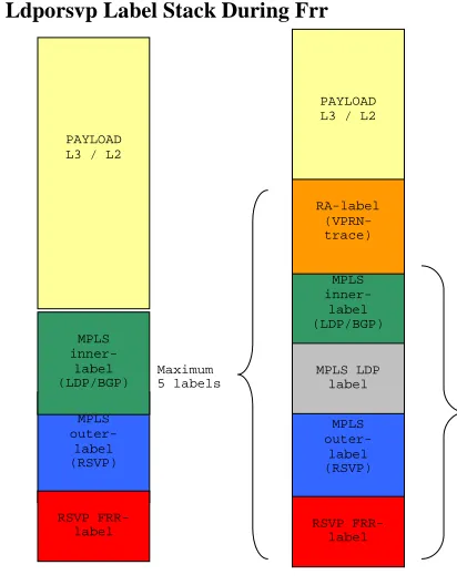
2.4. Ldporsvp Label Stack During Frr
Figure 3. LDPoRSVP labels stack during FRR
Nota: when deploying LDPoRSVP and enabling FRR (facility) as protection mechanism keep the 4 potential MPLS labels into account for MTU definition
2.5. Lab Setup And Tests Scope
• Inter-P traffic will be encapsulated in a tunnel.
• No impact on all PE configuration, Only P routers are concerned by (LDPoRSVP)
• The tunnel is a TLDP session, between each P, so full mesh of: n x P routers
• Each TLDP session is using an LSP which is dynamic
• Signaling protocol for LSP is RSVP-TE , using cspf
• CSPF is a modified version of SPF algo (Dijkstra) , used in ISIS
• CSPF algorithm finds a path which satisfy constraints for the LSP (our test limits only to one constraint: the shortest path igp)
PE
P
P
PE
P P
P
P CE
P
CE
MPLS outer-label (RSVP) PAYLOAD L3 / L2
MPLS inner-label (LDP/BGP)
MPLS outer-label (RSVP) MPLS inner-label (LDP/BGP)
MPLS LDP label PAYLOAD L3 / L2
RSVP
FRR-label RSVP FRR-label
RA-label (VPRN-trace)
[image:3.612.74.306.168.345.2]• Once a path is found by CSPF, RSVP uses the path to request the LSP establishment
Figure 4. LDPoRSVP Lab setup
2.5.1.Lab test method :
On each P router, we check that a (detour LSP is precalculated, presignaled for each LSP). We load heavily the P routers with:
• BGP routes vpn, internet
• IGP (ISIS) routes
• LDP labels
• TLDP sessions
• RSVP sessions
We generate traffic consisting of hundred thousands of packets in both directions, PE1 to
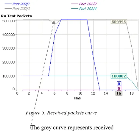
PE3 see (Fig.4), note that the chosen igp metrics will force then nominal path to be [PE1 - P1 - P3 - P4 - PE3] (the red path). We cut the link [P4 – P3] either by shutting the physical port or by removing the fiber from the port, we measure the convergence time through the number of lost packets related to the ratio:
[sent /received] packet/s.
[image:4.612.317.552.288.508.2]We check that, when the link [P4 – P3] goes down, the P3 router, instead of waiting the igp convergence, instantly uses the pre computed backup link [P3 – P1 - P2 - P4] (the green or detour path), then after the igp converges, the traffic goes, without impact, through the link [PE1 - P1 - P2 - P4 - PE3] (the blue path).
Figure 5. Received packets curve
The grey curve represents received packets, we notice a small traffic fall.
Table 1 .LDPoRSVP Traffic measurement
We check fast reroute performance at different load conditions: firstly we start with few LSPs
500 k vpn routes 60 TLDP neighbors 121 k internet routes
2000 LSP 1000 FEC
P1 P2
P3 P4
PE1 PE2
PE3
100
1000 10
10 50 100
1000
Legend:
Simulator Access points
PE router
P router
Nminal traffic
Emulated P router
Fast RR traffic
After converg traffic
then we increase the number progressively: (500, 1000, 2000 …)
2.5.2.Test results:
We see that mainly: convergence time stays between:
20 msec < t < 100 msec, independently of number of LSP. We notice some issues regarding scalability of LDP FECs. The “on purpose” studied case in the Fig.4 shows that during the fast-reroute phase, traffic goes back to the sender before taking the good (remaining) path. This topology case would exist in a backbone design, so the sizing of the link must take into account the potential and transient traffic load.
3. LDP FASTREOUTE:
It’s a mechanism that providse a local protection for an LDP FEC by pre-computing and downloading to the “forwarding plane hardware”: both a primary and a backup NHLFE (Next Hop Label Forwarding Entry) for this FEC.
The primary NHLFE corresponds to the label of the FEC received from the primary next-hop as per standard LDP resolution of the FEC prefix in RTM (routing table manager). The backup NHLFE corresponds to the label received for the same FEC from a Loop-Free Alternate (LFA) next-hop.
• LFA next-hop pre-computation by IGP is described in RFC 5286.
• LDP FRR relies on using the label-FEC binding received from the LFA next-hop to forward traffic for a given prefix as soon as the primary next-hop is not available.
In case of failure, forwarding of LDP packets to a destination prefix/FEC is resumed without waiting for the routing convergence. The RTM module populates both primary and backup route and the “forwarding hardware” should populate both primary and backup NHLFE for the FEC.
3.1. Reminder Routes and LFA Computation
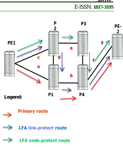
[image:5.612.324.539.69.329.2]Assuming : a,b,c,d,e,f,g represent the igp metrics on each node link:
Figure 6. LFA concept reminder
The primary route will be via P1 assumed that:
{a < (c + d)} and {(a + b) < (c + e + f)}
The LFA route via P2 and P1 protects against failure of the link PE1-P1:
• Loop Free Criterion (computed by PE1): The cost for P2 to reach P4 via P1 must be lower than the cost via routes PE1 then P1 {assumed d < (a + c )}
• Downstream Path Criterion (to avoid micro-loops): The cost of reaching P4 from P2 must be lower than the cost for reaching P4 from PE1 {assumed d <a }.
The LFA route via P2 and P3 protects against the failure of P1:Node-protect condition for P2 assumed that:
{(e + f) < (d+ b)}.
3.2. The SPF Algorithm Behavior:
• Attempt the computation of a node-protect LFA next-hop for a given prefix
• If not possible, attempt the computation of a link-protect LFA next-hop.
• If multiple LFA next-hops for a given primary next-hop are found, pick the node-protect in favor of the link-protect.
• If there is more than one LFA next-hop within the selected type, pick one based on the least cost.
PE1
PE-2
P1 P4
b a
c d
e
f g
Primary route
LFA link-protect route P
2 P3
LFA node-protect route
• If more than one have the same cost, the one with the least (outgoing interface: OIF) index is selected.
Both the computed primary next-hop and LFA next-hop for a given prefix are programmed into the routing table management.
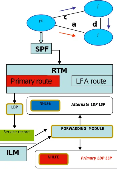
[image:6.612.312.524.113.385.2]3.3. LDP Fast Reroute Operation
Figure 7. LDP Fastreroute operation
When LFA and LDP FRR are enabled, LDP use both the primary next-hop and LFA next-hop, when available, for resolving the next-hop of an LDP FEC against the corresponding prefix in the RTM. This results in LDP programming a primary NHLFE and a backup NHLFE into the “forwarding module” for each next-hop of a FEC prefix for the purpose of forwarding packets over the LDP FEC.
[image:6.612.83.288.220.519.2]3.4. Failure Event and Restoration
Figure 8. LDP Fast reroute failure event and restoration
Upon failure event (1), LDP instructs in the fast path the Forwarding module to enable the backup NHLFE for each FEC next-hop impacted by this event (2). Forwarding is resumed. LDP will also update the impacted ILMs (LSR) and service records (LER) to use the backup NHLFE as their primary NHLFE until the next routing update (3).
3.5. Failure Triggers for LDP FRR
Backup NHLFE are activated upon any of the following condition:
LDP interface down: physical or admin shutdown.
• Then LDP sends a neighbor down event to the forwarding modules for each LDP peer it has adjacency with over this interface.
LDP session down as the result of the Hello or Keep-Alive timer expiring.
• Then LDP sends a neighbor down event to the forwarding modules for this LDP peer only.
TCP connection used by a link LDP session down (e.g, due to NH tracking):
NHLFE Alternate LDP LSP
P2
P1
PE1
a
d
SPF
Primary route
RTM
LFA route
LDP
Service record
ILM
NHLFEPrimary LDP LSP 1
2
3
FORWARDING MODULE
c
NHLFE Alternate LDP LSP
P2
P1
PE1
a
d
SPF
Primary route
RTM
LFA route
FORWARDING MODULE LDP
Service record
ILM
NHLFE• Then LDP sends a neighbor down event to the IOMs for this LDP peer only.
Timeout of BFD session enabled on a L-LDP/T-LDP session
• Then LDP sends a neighbor down event to the IOMs for this LDP peer only.
At same time IGP will start to converge and LDP will program new primary/backup NHLFE as soon as protocol is converged. Switchover from old backup NHLFE to new primary NHLFE should be hitless.
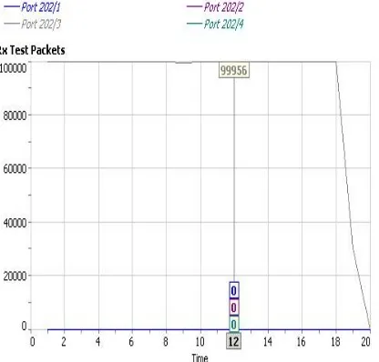
3.6. Ldp Fastreoute: Lab setup and test method:
Figure 9. LDP Fastreroute Lab setup
[image:7.612.74.540.102.697.2]Table 2. Example of LFA precomputation
Table 3. LFA Lab coverage percentage
3.6.1.Lab test method
Same as described before in (2.5.1) except here, we cut the inter P link [P1 - P3], the backup path is [P1 - P2 - P4]. We measure the convergence time through the number of lost packets related to the ratio:
[image:7.612.320.528.503.702.2][sent /received] packet/s.
Figure 10. received traffic curve
P1# show router isis routes alternative 10.0.222.5/32 Route Table Prefix[Flags] Metric Lvl/Typ Ver.
NextHop MT AdminTag Alt-Nexthop Alt-Metric Alt-Type --- 10.0.222.5/32 11130 2/Int. 4950 P3
10.0.79.21 0 0 10.0.70.49 (LFA) 11140
nodeProtection
---
P1# show router isis lfa-coverage
================================================ LFA Coverage
================================================ Topology Level Node IPv4 IPv6
---IPV4 Unicast L1 0/0(0%) 3257/3260(99%) 0/0(0%) IPV4 Unicast L2 27/28(96%) 3257/3260(99%) 0/0(0%) ================================================
500 k vpn routes 60 TLDP neighbors 121 k internet routes
2000 LSP 1000
P1 P2
P3 P4
PE1 PE2
PE3
10
1000 10
10 50 10
110
Legend:
Simulato r Access points PE
t
P
t
Nominal
Emulated P
t
Table 4 .LDP-FRR Traffic measurement
3.6.2.LDP Fast-Reroute test results:
We see that mainly: convergence time stays around 5 ms. This makes the LDP fast-reroute more attractif, however it doesn’t offer a 100% topology coverage.
4. CONCLUSION:
In this paper we presented a comparative study of RSVP-TE versus LDP(/IP) FRR, here is the outcome summarize:
RSVP-TE gains: Fast convergence « P »
(detour LSP is pre calculated, pre signaled for each LSP. A convergence time around: 20 msec < t < 100 msec.
RSVP-TE drawbacks: Additional level of
routing complexity; requires P-P trunk support rsvp, TLDP sessions, additional cpu load (rsvp msg).
LDP(/IP) FRR gains: Local decision, no
interoperability issues with other vendors. Very simple configuration (just turn it on). Better scaling compared to full-mesh RSVP model. Less overhead compared to RSVP soft-refresh states
LDP(/IP) FRR drawbacks: Lower backup
coverage, depending on topologies may vary between 65 to 85%, indeed, the source routing paradigm: LDP will always follows IP route, so if a candidate backup router has its best route through originating node, this candidate node can not be chosen as backup.
While the conceptual restriction of LDP(/IP) FRR is efficient against loops, it doesn’t allow a 100% coverage of all topologies, however we can reach a good compromise by a mixture of both, RSVP shortcuts will be deployed if and where LDP(/IP) FRR cannot offer coverage.
Finally, we consider this work as a part of a global research on the “network convergence item”, it deals with the state of the art, the convergence characterization on a core backbone with IGP and BGP load, and with some standard features and interoperability. A Next step would be modeling new protocol concepts holding intrinsically the convergence as a constraint.
REFRENCES:
[1]. Nuova Systems, K. Kompella Juniper Networks, JP. Vasseur Cisco Systems, Inc., A. Farre Old Dog Consulting. Label Switched Path Stitching with Generalized Multiprotocol Label Switching Traffic Engineering (GMPLS TE).
[2]. Atlas, Ed BT, A. Zinin, Ed. Alcatel-Lucent. Basic Specification for IP Fast Reroute: Loop-Free Alternates (RFC 5286).
[3]. E. Oki,T. Takeda NTT, A. Farrel Old Dog Consulting. Extensions to the Path Computation Element Communication Protocol (PCEP) for Route Exclusions.
[4]. L. Andersson Nortel Networks Inc., P. Doolan Ennovate Networks, N. Feldman IBM Corp, A. Fredette PhotonEx Corp, B. Thomas Cisco Systems Inc. LDP Specification (RFC 3036).
[5]. D. Awduche Movaz Networks, Inc., L. Berger D. Gan Juniper Networks, Inc. T. Li Procket Networks, Inc. V. Srinivasan Cosine Communications, Inc. G. Swallow Cisco Systems, Inc. RSVP-TE: Extensions to RSVP for LSP Tunnels (RFC 3209).
[6]. D. Awduche, J. Malcolm, J. Agogbua,M. O'Dell, J. McManus UUNET MCI Worldcom (RFC-2702).
[7]. E. Rosen, Y. Rekhter. BGP/MPLS IP Virtual Private Network (VPNs) (RFC-4364).
[8]. Ina Minei, julian Lucek Juniper Networks, MPLS-Enabled Applications,Emerging Developments and New Technologies.
[9]. L. AnderssonNortel Networks Inc, P. Doolan Ennovate Networks N. Feldman IBM Corp, A. Fredette PhotonEx Corp, B. Thomas Cisco Systems, Inc. (RFC-3036).
[10]. P. Pan, Ed. Hammerhead Systems, G. Swallow, Ed. Cisco Systems, A. Atlas, Ed. Avici Systems (RFC-4090).
[12]. Y. Rekhter, E. Rosen. BGP MPLS Carrying Label Information in BGP-4 (RFC 3107).
[13]. Y. Rekhter, T. Li, S. Hares, A Border Gateway Protocol 4 (BGP-4) (RFC-4271). [14]. Alia K. Atlas (editor), Raveendra Torvi,
FutureWei Technologies Inc, Gagan Choudhury: IP Fast Reroute: Loop-Free Alternates (RFC 5286)
[15]. P.Marques, R.Bonica from Juniper Networks, L.Fang, L.Martini, R. Raszuk, K.Patel, J.Guichard From Cisco Systems, Inc. Constrained Route Distribution for Border Gateway Protocol/MultiProtocol Label Switching (BGP/MPLS) Internet Protocol (IP) Virtual Private Networks (VPNs). (RFC 4684)
[16]. Susan Hares, NextHop Technologies Scaling MPLS Software to Meet Emerging VPN Demands.
[17]Zhuo (Frank) Xu Alcatel-Lucent SRA N0.1. Designing and Implementing IP/MPLS-Based Ethernet Layer 2 VPN Service.
![Assessment of Physiological Health Status in Relations to Different Anthropometric and Cardio respiratory Measures of Head Supported Load Carrying Male Porters of Sikkim, India [Article Retracted]](data:image/gif;base64,R0lGODlhAQABAIAAAP///wAAACH5BAEAAAAALAAAAAABAAEAAAICRAEAOw==)