DESIGN PARAMETER OPTIMIZATION BASED ON
ARTIFICIAL BEE COLONY (ABC) ALGORITHM FOR MEMS
ACCELEROMETERS
1KRUSHNASAMY V.S, 2A.VIMALA JULIET
1
Assistant Professor, Department of ICE, SRM University, KATTANKULATHUR
2 Professor and Head, Department of ICE, SRM University, KATTANKULATHUR
E-mail: [email protected], [email protected]
ABSTRACT
As MEMS technology continue to grow, MEMS device design optimization is becoming an interesting and important research issue. In order to design a MEMS device to meet the given specifications, the relationship between the device performance and various design parameters must be investigated. There are various optimization algorithms that can produce an optimized design of MEMS. Designing of MEMS accelerometer may include the parameters like Beam length, Beam width, Beam depth, Beam mass, proof mass etc. The primary intension of this research is to identify the optimal parameters to design an efficient accelerometer in MEMS. Here the optimization will be done by using Artificial Bee Colony Optimization (ABC) algorithm. This algorithm will overcome the issues of GA and the ABC based design parameter optimization technique will helpful to design MEMs accelerometer architecture. The fitness is based on the parameter die area with specified range. The implementation of the proposed method will be done by MatLab 7.12 and the performance will be analyzed with some existing methodologies.
Keywords: ABC(Artificial Bee Colony),MEMS,Optimization,Accelerometer,GA
1. INTRODUCTION
MEMS is a process technology used to create tiny integrated devices or systems that combine mechanical and electrical components. They are fabricated using integrated circuit (IC) batch processing techniques and can range in size from a few micrometers to millimeters.[2] These devices (or systems) have the ability to sense, control and actuate on the micro scale, and generate effects on the macro scale. MEMS have been identified as one of the most promising technologies for the 21st Century and have the potential to revolutionize both industrial and consumer products by combining silicon based microelectronics with micromachining technology. Its techniques and micro system based devices have the potential to dramatically affect of all of our lives and the way we live. If semiconductor micro fabrication was seen to be the first micro manufacturing revolution, MEMS is the second revolution [4].
MEMS range from simple beams and electrostatic gaps to more complex sensors and actuators that include fluidic, magnetic, and thermal systems. Modern methodology of MEMS design implies that the entire MEMS can be investigated
only at higher abstraction levels such as schematic and system ones, where accurate macro model scan be used [1]. On the other hand, at component or device levels the physical behavior of three-dimensional continuums is described by partial differential equations (PDE) solvable by Finite Element or Finite Difference Element Methods (FEM or FDM)[2]. Micro-Electro-Mechanical Systems consists of mechanical elements, sensors, actuators, and electrical and electronics devices on a common silicon substrate [3]. The sensors in MEMS gather information from the environment through measuring mechanical, thermal, biological, chemical, optical, and magnetic phenomena. The electronics then process the information derived from the sensors and through some decision making capability direct the actuators to respond by moving, positioning, regulating, pumping, and filtering, thereby controlling the environment for some desired outcome or purpose. [2]
millimeter.[9] These have been used as sensors for pressure, temperature, mass flow, velocity, sound and chemical composition, as actuators for linear and angular motions, and as simple components for complex systems such as robots, lab-on-a-chip, micro heat engines and micro heat pumps.[1] The Lab on-a-chip in particular is promising to automate biology and chemistry to the same extent the integrated circuit has allowed large-scale automation of computation
Accelerometers for automobile airbags, keyless entry systems, dense arrays of micro mirrors for high definition optical displays, scanning electron microscope tips to image single atoms, micro heat exchangers for cooling of electronic circuits, reactors for separating biological cells, blood analyzers, and pressure sensors for catheter tips are but a few of the current usages. Micro ducts are used in infrared detectors, diode lasers, miniature gas chromatographs, and high-frequency fluidic control systems. Micro pumps are used for ink jet printing, environmental testing, and electronic cooling. Potential medical applications for small pumps include controlled delivery and monitoring of minute amount of medication, manufacturing of nanoliters of chemicals, and development of artificial pancreas. [4]. Commercial tools like MEMCAD (Microcosm Technologies) [3] and MEMS Modeler (MEMSCAP) use parametric curve-fitting of simulation data to obtain macro models.[6] The primary drawback of these methods is that they do not generate scalable macro models
However, the greatest potential for MEMS devices lies in new applications within telecommunications (optical and wireless), biomedical and process control areas Military use of MEMS such as triggers for weapons, micro-gyros, micro-surety systems, and micro-navigation devices give another dimension to the importance of reliability of these devices.[9] Any accidental triggering may Claim many lives and, if in a warehouse, may have a domino effect. Initial air bag technology used conventional mechanical ‘ball and tube’ type devices which were relatively complex, weighed several pounds and cost several hundred dollars. They were usually mounted in the front of the vehicle with separate electronics near the airbag. MEMS have enabled the same function to be accomplished by integrating an accelerometer and the electronics into a single silicon chip. Another example of an extremely successful MEMS application is the miniature disposable pressure sensor used to monitor blood pressure in hospitals. These sensors connect to a patient’s intravenous (IV) line and monitor the blood
pressure through the IV solution. For a fraction of their cost ($10), they replace the early external blood pressure sensors that cost over $600 and had to be sterilized and recalibrated for reuse.[2]
MEMS have several distinct advantages as a manufacturing technology [1]. In the first place, the interdisciplinary nature of MEMS technology and its micromachining techniques, as well as its diversity of applications has resulted in an unprecedented range of devices and synergies across previously unrelated fields (for example biology and microelectronics).Secondly, MEMS with its batch fabrication techniques enables components and devices to be manufactured with increased performance and reliability, combined with the obvious advantages of reduced physical size, volume, weight and cost. Thirdly, MEMS provides the basis for the manufacture of products that cannot be made by other methods. These factors make MEMS potentially a far more pervasive technology than integrated circuit microchips. However, there are many challenges and technological obstacles associated with miniaturization that need to be addressed and overcome before MEMS can realize its overwhelming potential. MEMS is a manufacturing technology; a paradigm for designing and creating complex mechanical devices and systems as well as their integrated electronics using batch fabrication techniques.
A number of actuators operate by thermal actuation that imposes relatively high temperatures and require resistance against thermal cycling, high temperature fatigue or creep. All these issues necessitate rigorous mechanical tests, on MEMS scale, to examine the effect of various processing parameters, types of loading, service environments and temperatures for different materials and applications [4] Components such as micro mirrors that have several levels of alignment controls using structural hinges operating at high frequencies suffer from cyclic fatigue damage accumulation and may fail by crack initiation and propagation under cyclic loading [2].
The rest of the paper is organized as follows. Section II provides various researches conducted in relation to our proposed work. Section III explains about the design strategy and the proposed method. Section IV shows the result and discussion of our proposed method and finally section V concludes our proposed method for design parameter optimization of MEMS accelerometer.
2. RELATED WORKS
The inception of MEMS devices occurred in many places and through the ideas and endeavors of several individuals. And of course, new MEMS technologies and applications are being developed every day. Following is a timeline which includes many efforts leading to MEMS development. This lesson by no means includes all the efforts put forth in developing MEMS technology and applications. It gives a broad look at some of the milestones which have contributed to the development of Microelectromechanical Systems as we know them today
Zhang et al. [6] implemented a hierarchical MEMS synthesis and optimization architecture, integrating an object-oriented data structure with SUGAR and two types of optimization: genetic algorithms (GA) and local gradient-based refinement. They noted that the MOGA approach needed a means for automating the starting populations for MOGA that would enable a larger sampling of the solution space of MEMS design. Jain et al. [5] developed a MEMS transducer for an ultrasonic flaw detection system. This experiment appears to be the first to attempt ultrasonic signal detection by MEMS transducers in direct contact with solids.
Attoh-Okine et al. [7] Proposed the potential applications of MEMS in pavement engineering and highlighted some of the potential applications. They highlighted both the advantages and disadvantages of MEMS within pavement engineering applications they also developed an experimental protocol for the use of MEMS resonator sensors in monitoring micro cracking in concrete
Kamalian et al. [9] extended Zhou’s work to more advanced MEMS problems and explored interactive evolutionary computation (IEC), integrating human expertise into the synthesis loop to leverage the strength of human expertise with computational efficiencies.
Li and Anton son [2] applied GAs to the mask-layout aspect of MEMS synthesis. Ma and Anton son [4] also used GAs for automated mask-layout synthesis, but extended their work to include process synthesis for MEMS. Given a desired MEMS device topology and fabrication process, their tool could produce mask layouts and associated fabrication steps for a particular MEMS device. GAs was used to evolve an optimal mask layout given a user-defined shape. Li et al. [3] also concentrated on developing automatic fabrication process planning for MEMS Devices for the later
stages of MEMS product development, once a designer always has a defined device concept. Obadat et al. [10] developed full-scale MEMS-based biaxial strain transducers for monitoring the fatigue state of railway track. A unique feature of this work involves the combined use of the finite element method (FEM) and MEMS. FEM analysis was used to determine the critical fatigue locations where the MEMS transducers were to be attached to these locations.
Since the invention of the transistor, scientists have been trying to improve and develop new micro electromechanical systems. MEMS devices have been used in so many commercial products. New applications and better technologies are emerging every day. The first MEMS devices measured such things as pressure in engines and motion in cars. Today, MEMS elements are controlling our communications networks. They are saving lives by inflating automobile air bags. They are placed in the human body to monitor blood pressure and used to administer drugs when and directly where they are needed.
3. PROPOSED METHODOLOGY
technique for selecting the design parameters of MEMS accelerometer.
3.1 Optimized Parameter Design of Micro-Electro-Mechanical System Accelerometer
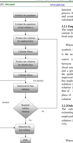
The importance of MEMS optimization is its dependency in concerning performance, power consumption, and reliability increases. There are various optimization algorithms that can produce an optimized design of MEMS. The optimization algorithm mainly focuses on the objective function or fitness function. In our proposed method we have utilized the Artificial Bee Colony Optimization algorithm for optimizing the design of MEMS Accelerometer. Various parameters that are required for the accelerometer design of MEMS includes the Beam length, Beam width, Beam depth, Beam mass, proof mass etc. The flow diagram for our proposed methodology is given in fig1. As shown in the figure, the various design parameters of the accelerometer is selected and for each of these parameters the optimization process is carried out using the ABC algorithm and the finally optimized parameters are obtained as the final solution.
Fig 1: Block Diagram For Our Proposed Design Optimization Of MEMS Accelerometer.
3.1.1 Design parameters of MEMS accelerometer
The MEMS accelerometer design in our proposed method is employed with the aid of the various design parameters like Beam length, Beam width, Beam depth, Beam mass, proof mass etc.To begin the process a MEMS designer will approach the system and select a MEMS design domain of interest such as accelerometer as in our method because a concept domain must be selected before
one can begin entering design specifications. Once this is done, the designer inputs their design specifications for these various parameters. The parameters and its specifications can be represented below as follows,
Beam Length : Z {Z1, Z2, Z3, Zj}
Beam Width : H {H1, H2, H3, Hj}
Beam Depth : D {D1, D2, D3, Dj}
Beam Mass : m {xm, ym}
Proof Mass : k {xk, yk}
Of these parameters, Z1, Z2, Z3, yk should be
optimized to produce the optimal design of MEMS. The remaining parameters are assigned with the constant values as follows,
H1=H2 =H3=Hj=A (1)
B D D D
D1= 2 = 3= j = (2)
Where A=B=1.8µ m.
The MEMS accelerometer diagram specifies all the parameters that can be used to get an optimal design of MEMS. It makes use of a folded beam structure. The structure is specified as follows,
Fig 2: MEMS Accelerometer With Design Parameters
The MEMS accelerometer diagram specifies all the parameters that can be used to get an optimal design of MEMS. It makes use of a folded beam structure. The parameter values is specified as follows,
P
Zj = (3)
Q
ym= (4)
1 2H
Z
xm = j+ (5)
3 1
2 2 2
2Z H H
H
xk = j+ + + (6)
Where P=150µm, Q=100µ m.
Whereas the other parameters like Z1, Z2, Z3, yk
should be in the following ranges,
Z1=R (7)
Z2=S (8)
yk =U (10) Where 20 µm≤ R ≤ 500 µm, 20 µm≤ S≤ 100 µ m, 100 µm ≤ T ≤ 500 µm, 100 µm ≤ U ≤ 500 µm. The parameters are optimized using the ABC algorithm. The process of ABC is explained below.
3.2 Artificial Bee Colony Algorithm for Optimization of Design Parameters
Artificial Bee Colony (ABC) is a novel optimization algorithm inspired of the natural behavior of honey bees in their search process for the best food sources [16]. In the ABC algorithm, the colony of artificial bees contains three groups of bees: employed bees, onlookers and scouts [14] [18]. At the initialization step, a set of food source positions are randomly produced and also the values of control parameters of the algorithm are assigned [17]. The nectar amount retrievable from food source corresponds to the quality of the solution represented by that food source. So the nectar amounts of the food sources existing at the initial positions are determined [19]. A bee waiting on the dance area to obtain the information about food sources is called an onlooker, a bee going to the food source is named as an employed bee, and a bee carrying out random search is called a scout [20].
The goal of bees in the ABC model is to find the best solution, the position of a food source represents a possible solution to the optimization problem and the nectar amount of a food source corresponds to the quality (fitness) of the associated solution [15]. After sharing their information with onlookers, every employed bee goes to the food source area visited by herself at the previous cycle since that food source exists in her memory, and then chooses a new food source by means of visual information in the neighborhood of the one in her memory and evaluates its nectar amount [13]. At the second stage, after sharing the information, every employed bee goes to the food source area visited by herself at the previous cycle since that food source exists in her memory, and then chooses a new food source by means of visual information in the neighborhood of the present one [11].At the third stage, an onlooker prefers a food source area depending on the nectar information distributed by the employed bees on the dance area [12]. When the source is abandoned, the employed bee becomes a scout and starts to search a new source in the vicinity of the hive.
In ABC algorithm the possible solutions for the optimization problem can be denoted by the
position of a food source and the fitness of a related solution can be obtained by the nectar quantity of food source. The quantity of solutions in the population is equal to the quantity of the employed bees or the onlooker bees. At first cycle, ABC produces a randomly distributed initial population of solutions. After initialization, the population of the solutions is focused to the replicated cycles of the search process of the employed bees, the onlooker bees and the scout bees. An employed bees generates alteration on the solution in their memory depending on the area knowledge and verify the nectar quantity of the new solution. If the nectar quantity of the new one is better than that of the earlier one, the bee memorizes the new position and forgets the old one or else it memorize the earlier position in their memory. The employed bees, after their completion of search process it shares the nectar knowledge of the food sources and their position knowledge with the onlooker bees. Then onlooker bees estimate the knowledge from the employed bees and select a food source with a probability similar to its quantity. If it is satisfied means then we can memorize the solution and stop the process, otherwise the process have to be repeated until the new solution satisfies the eligible criteria. The working process of the ABC algorithm is based on the fitness value of the solution and the flow diagram given below shows the overall process that is being carried out in the ABC algorithm.
The fig 3 shows the entire process of ABC algorithm. The first stage is the initialization of the population which is followed by the fitness calculation. The procedure of fitness calculation is carried out for employed bees as well as the onlooker bees. The algorithm is terminated only when the conditional criteria is met. By using ABC algorithm the intensity parameters are adjusted and improved output image is obtained. The proposed ABC algorithm is explained below.
Fig 3: Optimization ProcessIin ABC
The objective function or Fitness function for the MEMS design is represented by,
Α
=D
F (11)
Where, DA is the Die Area. The Die Area DA can be evaluated by the following equation,
m
m L L L W y
x
DΑ=(( +2 2+( 3− 1)+2 2) (12) Die Area value can be between 90,000 to 160,000µm2 and it can be relaxed up to 240,000 µ m2
The maximum fitness value is considered as the best food source and by keeping this fitness
function as initial stage we start our searching process by using employed bees, onlooker bees, and scout. The initial stage of fitness function is calculated.
3.2.1 Employed bees
The employed bee searches the neighborhood of its current food source (solution) to find out a new food source (new solution) using the equation (13)
(
i l)
f f
f X X X
C = +ω − (13) Where,
l
andf
are the arbitrary selected symbols. Herel
is the very next value off
orl
is the next chance off
to find the new food source (solution).ω
f is a random numberbetween
[
−1,1]
. After creating the new solution (food source), the quantity of it will be determined and a greedy choice process will be presented. If the quality of a new food source (solution) is improved than the existing position, the employed bee neglects that position and moves towards new solution (food source), or else the fitness of a new solution (food source) is equal or improved than that of Xi , therefore the new solution takes the place of Xi in the population and becomes a new solution.3.2.2Onlooker bees
The onlooker bees select a food source by estimating the knowledge obtained from all of the employed bees. The probability pi of choosing the solution (food source) is evaluated by the equation (14),
∑
=
= n
f f
F F P
1
(14)
manner which helps in improving the design process of the MEMS accelerometer.
4.
RESULT AND DISCUSSIONBy applying the ABC algorithm we have obtained the optimal values for L1, L2, L3, ym. In
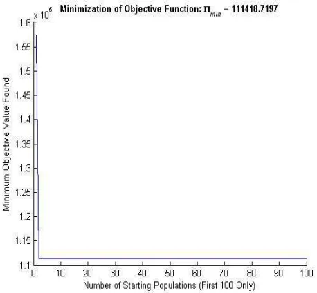
[image:7.612.315.533.80.298.2]our method we have used totally thousand iterations to obtain the optimal design. The optimization process has minimized the die area, represented by the objective or fitness function F, by satisfying the design criteria. The best performing design was saved for each successive starting population to converge on the optimum values. The results had been displayed for the following iterations and the optimum values obtained by the ABC algorithm have also been described in the tables.
[image:7.612.80.287.340.624.2]Fig 4: Minimization Of Objective Function In The 100th Iteration
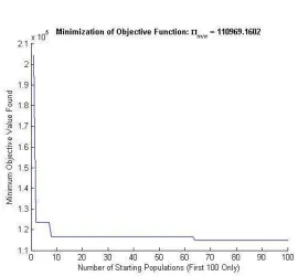
Fig 5: Minimization Of Objective Function In The 200th Iteration
[image:7.612.322.551.373.585.2]Table 1: Five Optimal Values Obtained In The 100th Iteration By ABC Algorithm
[image:8.612.120.502.241.607.2]Table 2: Five Optimal Values Obtained In The 200th Iteration By ABC Algorithm
[image:8.612.174.444.359.609.2]Table 3: Five Optimal Values Obtained In The 400th Iteration By ABC Algorithm
Fig 7: Final Minimization Of Objective Function
The table 1,2 and 3 shows the optimal values Obtained for 100th,200thand 400th iteration.Five optimal values for each of the iterations are found out and tabulated. The corresponding graphical representation is shown in the fig 4,5 and 6 respectively with the minimized objective function.
The fig 7 shows the graphical representation of the Final Minimization of Objective function using ABC algorithm.
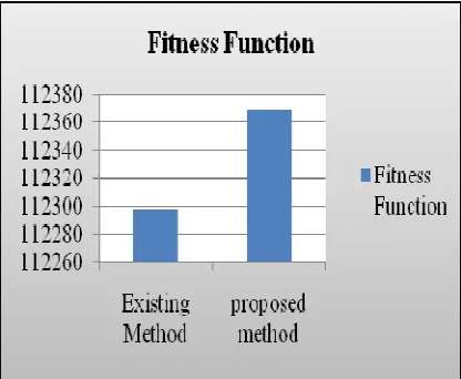
The table given below shows the comparison of the fitness value that is obtained using our proposed method and the existing method using the genetic
Iteration L1 L2 L3 Ym F
Rank 1 2.814e-05 5.817e-05 4.746e-04 1.009e-04 111739.81521 Rank 2 2.592e-05 6.620e-05 4.654e-04 1.004e-04 111820.19521 Rank 3 2.592e-05 6.620e-05 4.654e-04 1.004e-04 111820.19521 Rank 4 2.592e-05 6.620e-05 4.654e-04 1.004e-04 111820.19521 Rank 5 2.592e-05 6.620e-05 4.654e-04 1.004e-04 111820.19521
Iteration L1 L2 L3 Ym F
Rank 1 2.100e-05 5.446e-05 4.897e-04 1.010e-04 111979.77470 Rank 2 2.100e-05 5.446e-05 4.897e-04 1.010e-04 111979.77470 Rank 3 2.100e-05 5.446e-05 4.897e-04 1.010e-04 111979.77470 Rank 4 2.100e-05 5.446e-05 4.897e-04 1.010e-04 111979.77470 Rank 5 2.315e-05 6.079e-05 4.800e-04 1.007e-04 112358.53887
Iteration L1 L2 L3 Ym F
algorithm. The fitness value proved to have improved than the existing method.
Table 4: Comparison Of Fitness Value Using The Existing And Proposed Method
Methods Fitness function Existing method 112297.95163 Proposed method 112369.1602
[image:9.612.93.301.269.440.2]
The graphical representation for the comparison of two methods is given in fig 8 below. As shown in the graph the fitness value of the proposed method is improved using the ABC algorithm when compared with that of genetic algorithm.
Fig 8: Graphical Representation Of Fitness Value Using The Existing And Proposed Method
5. CONCLUSION
In this paper, we have proposed a system to perform the optimization of the design parameters in the MEMS accelerometer. For this, we have employed Ant Bee Colony optimization algorithm which provides an efficient optimization technique. The result shows that our proposed method has delivered better results in terms of the fitness values when compared to other optimization techniques like genetic algorithm and also better optimization. This algorithm will overcome the issues of GA and the ABC based design parameter optimization technique will helpful to design MEMs accelerometer architecture. The fitness is based on the parameter die area with specified range.
REFRENCES:
[1] Kim, M., Hacker, J. B., Mihailovich, R. E., & DeNatale, J. F. ,”A DC-to-40 GHz four-bit RF-MEMS true-time delay network”, Microwave and Wireless Components Letters, IEEE, Vol.11, No.2, pp. 56-58. 2001.
[2] Neukermans, A., & Ramaswami, R.,” MEMS technology for optical networking applications”, Communications Magazine, IEEE, Vol.39, No.1,pp. 62-69, 2001.
[3] Cetiner, B. A., Jafarkhani, H., Qian, J. Y., Yoo, H. J., Grau, A., & De Flaviis, F. “Multifunctional reconfigurable MEMS integrated antennas for adaptive MIMO systems”, Communications Magazine, IEEE, Vol.42,No.12, pp. 62-70. 2004.
[4] Udina, S., Bosch, J., Pardo, A., Calaza, C., & Marco, S. “A MEMS based compact natural gas analyzer implementing IEEE-1451.2 and BS-7986 smart sensor standards”, Tagungsband, pp.1213-1216, 2012.
[5] Thuau, D., Dubourg, G., Haupt, K., Pellet, C., Poulin, P., Dufour, I., & Ayela, C. “Integration of functional polymers in organic MEMS for sensing applications”, In.proc.of. 10th International Workshop on Nanomechanical Cantilever Sensors, 2013.
[6] Deng, L., Kundur, V., Naga, N. S. J., Ozel, M. K., Yilmaz, E., Ozev, S,& Dar, T. “ Electrical calibration of spring-mass MEMS capacitive accelerometers”, In.Proc.of the Conference on Design, Automation and Test in Europe , pp. 571-574,2013.
[7] Tu, R., Wang, R., Ge, M., Walter, T. R., Ramatschi, M., Milkereit, C.,& Dahm, T, “Cost‐effective monitoring of ground motion related to earthquakes, landslides or volcanic activity by joint use of a single‐frequency GPS and a MEMS accelerometer”, In.proc.of Geophysical Research Letters, 2013.
[8] Frank, K., Nadales, M. J. V., Robertson, P., & Angermann, M, “Reliable real-time recognition of motion related human activities using MEMS inertial sensors”, In.Proc.of the 23rd International Technical Meeting of the Satellite Division of the Institute of Navigation, pp. 2906-2912, 2010.
[10] Laboriante, I., Suwandi, A., Carraro, C., & Maboudian, R, “Lubrication of polycrystalline silicon MEMS via a thin silicon carbide coating”, Sensors and Actuators A: Physical, 2013
[11] Dervis Karaboga · Bahriye Basturk, A powerful and efficient algorithm for numerical function optimization: artificial bee colony (ABC) algorithm, Journal of Global Optimization, Vol. 39, No. 3, Pp. 459–471, 2007.
[12] R. Srinivasa Rao, S.V.L. Narasimham, M. Ramalingaraju, Optimization of Distribution Network Configuration for Loss Reduction Using Artificial Bee Colony Algorithm, International Journal of Electrical Power and Energy Systems Engineering, Vol. 45, 2008. [13] Dervis Karaboga, Bahriye Akay, A
comparative study of Artificial Bee Colony algorithm, Journal of Applied Mathematics and Computation, Vol. 214, Pp. 108–132, 2009.
[14] Ali Hadidi, Sina Kazemzadeh Azad, Saeid Kazemzadeh Azad, Structural optimization using artificial bee colony algorithm, In proceedings of International Conference on Engineering Optimization, 2010
[15] Dervis Karaboga and Celal Ozturk, Fuzzy clustering with artificial bee colony algorithm, Journal of Scientific Research and Essays, Vol. 5, No. 14, pp. 1899-1902, 2010.
[16] Mohammad Shokouhifar, Gholamhasan Sajedy Abkenar, An Artificial Bee Colony Optimization for MRI Fuzzy Segmentation of Brain Tissue, In proceedings of International Conference on Management and Artificial Intelligence, Vol. 6, Pp. 6-10, 2011.
[17] Nadezda Stanarevic, Milan Tuba, and Nebojsa Bacanin, Modified artificial bee colony algorithm for constrained problems optimization, International Journal Of Mathematical Models And Methods In Applied Sciences, Vol. 5, No. 3, Pp. 644-651, 2011.
[18] Nurhan Karaboga, Mehmet Bahadır Cetinkaya, A novel and efficient algorithm for adaptive filtering Artificial bee colony algorithm, Turk J Elec Eng & Comp Sci, Vol.19, No.1, Pp. 175-190, 2011.
[19] Vijayarani, M.Sathiya prabha, Association Rule Hiding using Artificial Bee Colony Algorithm, International Journal of Computer Applications, Pp. 41-47, Vol. 33, No.2, 2011. [20] Miao Ma, Jianhui Liang, Min Guo, Yi Fan,
Yilong Yin, SAR image segmentation based