http://dx.doi.org/10.4236/opj.2016.61001
The Image Conversion in Optical
Echo-Holography by External
Electromagnetic Standing Waves
Guzel I. Garnaeva, Leonid A. Nefediev, Alsu R. Sakhbieva
Department of Educational Technologies in Physics, Kazan Federal University, Kazan, Russia
Received 25 September 2015; accepted 20 January 2016; published 25 January 2016
Copyright © 2016 by authors and Scientific Research Publishing Inc.
This work is licensed under the Creative Commons Attribution International License (CC BY). http://creativecommons.org/licenses/by/4.0/
Abstract
The recording and playback of information using a reverse stimulated photon—echo hologram when exposed to the recording medium pulse of non-resonant electromagnetic standing wave was considered. It was shown that the spatial intensity distribution in stimulated echo hologram re-sponse depended on the electric field intensity of non-resonant standing wave that allowed con-trolling by a reproducible image.
Keywords
Data Recording, Playback Information, A Reverse Stimulated Echo Hologram, Standing Wave, Control of the Reproduced Image
1. Introduction
The recording of dynamic echo-hologram in a case of coherent nonlinear interaction of laser pulses with a reso-nant medium allows for the memorization and reproduction of information about the dynamic processes asso-ciated with the change of states in space and time [1]-[5].
photon echo locking effect [8]-[10].
This work investigates the influence of non-resonant electromagnetic standing waves on image in a stimulated echo-hologram response when the first laser pulse is taken as object pulse.
2. Spatial Phase-Synchronism of Stimulated Echo-Hologram
We write the electric field intensity E1( )
r,t of the object laser pulse, as:( )
( ) (
)
(
)
1 , exp . . 0 1
E r t =U r −i t
ω
+c c ≤ ≤ ∆t t ,(1)
where ∆t1— the duration of the exciting laser pulse, and U r
( )
describes the spatial structure of the object la-ser pulse.Consider approximation where we can expand into a series of spherical or plane waves in the electric field in-tensity of the object laser pulse. The object will be regarded as a set of points with the radius vectors rn. Each point radiates a spherical wave. The totality of these waves in the location of j-th optical center with the radius vector r0j gives the value of the perturbation of the resonance transition of the optical center. In this case, the electric field intensity of the object laser pulse at the point r0j can be written as
(
)
{
0}
0
exp n j n n
j nj
n j n
i i t i
E
ω
ϕ
− − +
= Α
−
∑
k r rr r ,
(2)
where n n
c ω
=
k n , 0
0 j n n j n − = − r r n r r
, ϕn—the initial phases of the spherical waves, and exp
( )
iϕ
n can be in-cluded in the complex amplitudes Αnj (the index j indicates that in general the amplitudes Αnj may depend on the orientation nn). If r0j−rn symbol is much larger than the dimension of the medium in which echo- hologram is recorded, then the expansion into a series (2) in spherical waves is converted to the expansion into a series in plane waves:
{
0}
exp
j n n j
n
Е =
∑
ε ik r −i tω , (3)where εn—the amplitudes of the electric field intensity of the waves from the individual points of the object. At every point of the sample in this approximation, disturbance is almost created with the same set of plane waves. The best reproduction of information can be achieved by the use of stimulated echo-hologram (SEH). When recording stimulated echo-holograms possible two there are cases: when the first laser pulse is an object pulse or the second laser pulse is an object pulse. In the first case, the wave front of stimulated echo-holograms response is a complex conjugate to the wave front of object laser pulse and for the individual spatial components, which only meet the following condition of spatial phase matching:
0n = − 1n+ 2+ 3
k k k k . (4)
In the second case
0n = − +1 2n+ 3
k k k k . (5)
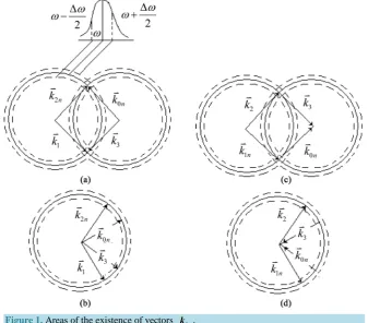
Figure 1 shows the region of existence of the wave vectors of SEH responses in the case of phase synchron-isms (4) (Figure 1(c) and Figure 1(d)) and (5) (Figure 1(a) and Figure 1(b)).
From Figure 1 and the conditions (4) and (5) it follows that only such vectors as k0n can exist in the stimu-lated echo hologram response, the ends of which lie in the region of intersection of the spherical surfaces. The width of this area
n c ω
∆
∆ =k ,
where ∆ω—the width of the excited part of the inhomogeneously broadened line of the resonance transition,
n—refractive index of the medium.
Figure 1. Areas of the existence of vectors k0n.
greatest area of intersection of spheres. Similarly, when the first laser pulse is an object pulse and k2 = −k3 we conclude that k0n = −k1n, and the angles between k1n and k2 can be any, as in this case, the greatest area of intersection of the spheres (Figure 1(d)).
Thus, the stimulated echo-holograms let you reproduce phase wave fronts of object laser pulses with the least distortion. This applies to the images recorded in the echo-holograms, since the image is determined by the in-tensity of the light propagating in the direction of the wave front.
3. Management of Angular Distribution of Amplitudes of the Stimulated
Echo-Holograms Response
The amplitudes of Αnj or εn which are associated with the directions of the spatial components propagation of the object laser pulse in the echo holograms response can be a function of the angles of βn of mutual orien-tation of the vectors kn relative to the direction in the sample along which creates an artificial anisotropy of additional frequency shifts of isochromates of inhomogeneously broadened resonance lines [11]. In the case where object pulse is the first laser pulse, the intensity electric field of the echo holograms response will be:
(
)
*(
)
1 00, ~ Re , e n
i R
n n
n
Е R t
∑
ε β′ t −k(6)
leading to a spatial redistribution of energy and consequent conversion of the stimulated echo-hologram’s re-sponse wave front. The most effective mechanism of influence on the values of the amplitudes of the expansion in plane waves of the electric field intensity stimulated echo-holograms response can be the effect of locking the photon echo upon exposure to non-resonant standing electromagnetic waves. In this case, there may be a change of the quantities ε βn′*
( )
n already at the angles βn in hundredths of a degree [11].To calculate the values *
( )
n n
[
,]
i B t ρ ρ ∂ = ∂ (7)
where
0m
B=H + −V A,
0 e 0 e
iAt iAt
m m
H = H − ,
eiAt e iAt V= V − ,
A—the transition matrix in the rotating coordinate system, V—the interaction operator of the resonant system with exciting laser pulses, H0m—Hamiltonian of an atom in an external spatially inhomogeneous nonresonant laser radiation acting on the time interval τm. In the case of two-level system Α =P22ω, Pij—projective matrix (its element ij is 1, and the others are 0),
11 22 e±iAt =P +P e±i tω ,
(
)
(
)
0m m, 22
H = f τ r P , V=P V12 12e−i tω +P V21 21ei tω ,
( )
( )
{
}
1 1
exp exp ,
2 2
ij ij ij n n
n
V = d U r i tω ≈ d
∑
ε −ik r+i tωω—frequency of the laser radiation, dij—dipole moment of the resonant transition,
r
—the radius vector optical center position, f(
τ
m,r)
—shift isochromatic of inhomogeneously broadened line in the external spa-tially inhomogeneous electromagnetic field. Dependence f(
τ
m,r)
from the location of the optical center in the sample is related to the spatial inhomogeneity nonresonant laser radiation. This inhomogeneity arises, for example, under the influence of a standing wave. In this case, for each direction of propagation of the plane wave in expansion (3) we have [12][13]:(
)
2 2( )
0
2π cos
, cos n
m D m
z
f τ C E β
λ
= ∆ +
r , (8)
where CD—constant dynamic Stark effect, E0m—the electric field intensity a standing wave nonresonant laser pulse, z—axis of the laboratory system coordinate along which a standing wave is formed, λ—a wavelength of nonresonant of laser radiation.
The solution of Equation (7) for a two-level system has been obtained in [13]. In this case, of phase part of the electric field stimulated echo holograms response has the form (6), where for the expansion coefficients
( )
*
n n
ε β′ we obtain
( )
( )
{
(
)
(
(
)
)
}
*
2 1 1
0
~ d d exp ,
L
n n z g i t f
ε β
∞τ
τ
τ
−∞
′
∫ ∫
∆ ∆ ∆ − − r (9)where L—dimension of the sample in the direction of the axis z, g(Δ)—frequency distribution function
inhomo-geneously broadened line of the resonance transition, τ1—the time interval between the first and second laser
pulses, τ2—the time interval between first and third laser pulses.
The integration in (9) with respect to z leads to a peculiar interference effect of radiation of individual optical centers depends on the direction of the radiation. In this case, there may be the effect of the spatial redistribution of the energy of response and, consequently, the transformation of its wave front. Note that this effect can be observed when the wave front of the object laser pulse is not planar.
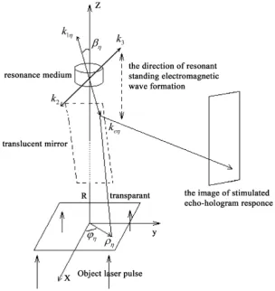
When image of transparant is recording using SEH and if the distance R from the transparant to the resonance medium is much greater than its size, you can use the expansion of the electric field intensity of the object laser pulse on the plane waves. Then for each of the n-th point of the transparant will match the wave vector k1n
having an angle βn with the axis z (Figure 2).
Consider the scheme of recording and playback SEH in inverted mode (Figure 2), the information is given as an image on the transparant and the SEH response is observed on the screen. To control the distribution of the intensity response SEH on the screen along the z-axis acts as a non-resonant electromagnetic standing wave, which leads to a different attenuation of the components of the SEH corresponding of different directions of vectors k1n. This leads to a redistribution of the SEH response intensity on the screen surface.
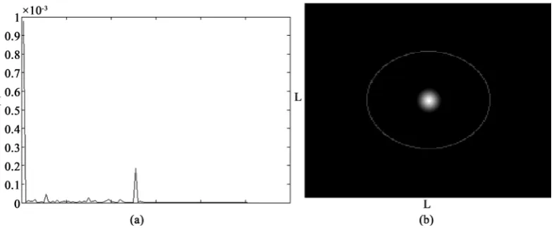
The results of numerical calculation of the expression (9) taking into account the expression (6) are shown in
[image:5.595.96.514.177.696.2]Figures 3-6. Figure 3 shows the distribution of the intensity on the screen in SEH response in the absence of non-resonant standing waves.
Figure 2. Formation SEH in reverse mode.
Figure 3. (a) The intensity distribution of SEH response on the screen. The origin of coordinate-center of a transparant. E1 =
[image:5.595.161.466.190.513.2]Figure 4. (а) The intensity distribution of SEH response on the screen. The origin of coordinate-center of a transparant. E1 = 100 V/cm, E2 = 0 V/cm; (b) Picture in SEH response on the screen. E1 = 100 V/cm, E2 = 0 V/cm.
Figure 5. (a) The intensity distribution of SEH response on the screen. The origin of coordinate-center of a transparant. E1 = 1000 V/cm, E2 = 0 V/cm; (b) Picture in SEH response on the screen. E1 = 1000 V/cm, E2 = 0 V/cm.
Figure 6. (a) The intensity distribution of SEH response on the screen. The origin of coordinate-center of a transparant. E1 = 2909 V/cm, E2 = 0 V/cm; (b) Picture in SEH response on the screen. E1 = 2909 V/cm, E2 = 0 V/cm.
[image:6.595.118.512.477.639.2]4. Conclusion
Exposure of non-resonant standing electromagnetic waves when recording SEH leads to the possibility of image control in SEH response. For certain values of electromagnetic standing waves intensities it is possible to obtain the concentration of energy in different areas of the image in the SEH response.
Funding
This work was funded by the subsidy allocated to Kazan Federal University for the state assignment in the sphere of scientific activities.
References
[1] Zuikov, V.A., Samartsev, V.V., Stelmakh, M.F., et al. (1991) Accumulated Long-Lived Photon Echo in LaF3:Pr3+ Cristal. Laser Physics, 1, 678-688.
[2] Manykin, E.A., Zhamensky, N.V., Marchenko, D.V., Petrenko, E.A. and Selifanov, M.A. (1992) Elaboration of Rapid Data Erasure Methods in an Optical Storage Device Based on the Photon Echo Effect. Optical Memory & Neural Networks, 1, 239-246
[3] Akhmediev, N.N. (1990) Information Erasing in the Phenomenon of Long-Lived Photon Echo. Optics Letters, 15, 1035-1037. http://dx.doi.org/10.1364/OL.15.001035
[4] Alexander, A.L., Longdell, J.J., Sellars, M.J. and Manson, N.B. (2007) Coherent Information Storage with Photon Echoes Produced by Switching Electric Field. Journal of Luminescence, 127, 94-97.
http://dx.doi.org/10.1016/j.jlumin.2007.02.034
[5] Kalachev, A.A. and Samartsev, V.V. (2003) Coherent Phenomena in Optics. Kazan State University, Kazan, 280.
[6] Nefediev, L.A. (1986) Peculiarities of the Formation of Echo Holograms with Three-Pulse Excitation of Resonant Me-dia. Journal of Applied Spectroscopy, 44, 419-423. http://dx.doi.org/10.1007/bf00661063
[7] Nefediev, L.A. (1986) Dynamic Echo Holography in Degenerate and Multilevel Systems. Izvestiya Akademii Nauk SSSR, Seriya Fizicheskaya, 50, 1551-1558.
[8] Nefediev, L.A., Hakimzyanova, E.I. and Garnaeva, G.I. (2013) The Long-Lived Photon Echo Response Locking Effect in the Presence of External Non-Resonant Laser Pulses with a Different Spatial Orientation. Optics and Photonics, 3, 360-363.
[9] Nefediev, L.A. and Garnaeva Khakimzyanova, G.I. (2008) Effect of Locking of Photon Echo Signals in Multichannel data Recording. Optics and Spectroscopy, 105, 924-929. http://dx.doi.org/10.1134/S0030400X08120187
[10] Nefediev, L.A., Garnaeva, G.I. and Ahmedshina, E.N. (2014) Locking Efficiency of Stimulated Photon Echo in Three-Level System Depending on Relative Orientation of Standing Waves of Non-Resonant Laser Pulses. Journal of Applied Spectroscopy, 81, 476-479.
[11] Zuikov, V.A., Nefediev, L.A. and Samartsev, V.V. (1982) Wave Front Reversal in Optical Echo-the Holograms and the Influence of the Movement of the Particles and Their Formation. Proceedings of Applied Issues of Holography, Leningrad, 12 October 1982, 175-179.
[12] Delone, N.B. and Krainov, V.P. (1978) An Atom in a Strong Laser Field. Science, Moscow, 286.