N A N O E X P R E S S
Open Access
Tuning nanoporous anodic alumina
distributed-Bragg reflectors with the number of
anodization cycles and the anodization temperature
Josep Ferré-Borrull
*, Mohammad Mahbubur Rahman, Josep Pallarès and Lluís F Marsal
Abstract
The influence of the anodization temperature and of the number of applied voltage cycles on the photonic properties of nanoporous anodic alumina-based distributed-Bragg reflectors obtained by cyclic voltage anodization is analyzed. Furthermore, the possibility of tuning the stop band central wavelength with a pore-widening
treatment after anodization and its combined effect with temperature has been studied by means of scanning electron microscopy and spectroscopic transmittance measurements. The spectra for samples measured right after anodization show irregular stop bands, which become better defined with the pore widening process. The results show that with 50 applied voltage cycles, stop bands are obtained and that increasing the number of cycles contributes to enhancing the photonic stop bands (specially for the case of the as-produced samples) but at the expense of increased scattering losses. The anodization temperature is a crucial factor in the tuning of the photonic stop bands, with a linear rate of 42 nm/°C. The pore widening permits further tuning to reach stop bands with central wavelengths as low as 500 nm. Furthermore, the results also show that applying different anodization temperatures does not have a great influence in the pore-widening rate or in the photonic stop band width.
Keywords:Nanoporous anodic alumina; Distributed-Bragg reflectors; Photonic properties tuning, Anodization temperature; Pore widening; Cyclic voltage anodization
Background
Nanoporous anodic alumina (NAA) is a material of great interest in nanotechnology because of its cost-effective and easily up-scalable production techniques [1-3] and also because of its vast field of applications [4-8]. This material consists of an array of cylindrical pores in an aluminum oxide matrix obtained by electrochemical anodization of aluminum. In the appropriate fabrication conditions, the pores self-arrange in a triangular lattice with domains containing several hundreds of pores [9]. This pore arrangement is usually obtained with three kinds of acid electrolytes (oxalic, phosphoric, or sulfuric) and in two different regimes, known as hard and mild anodization [10].
The photonic properties of NAA make this material specially interesting in optical applications such as bio-sensing [11-14] In previous works, the authors described
the existence of photonic stop bands for light propagat-ing inside the material [15] in a direction perpendicular to the pore axes, and also described a method to obtain distributed-Bragg reflectors (DBRs) [16] based on NAA. DBRs are dielectric multilayer structures [17-20] with a periodic variation of the refractive index in the direction perpendicular to the surface. This gives rise to photonic stop bands for light incident in a direction parallel to the pore axes. The central wavelength of such stop bands depends on the effective refractive index and on the optical thickness of each of the cycles, while the width of the bands is directly related with the contrast of the refractive index variations. Ideal photonic stop bands are achieved for infinite periodic structures [21,22]. How-ever, DBR structures are finite and consequently, the characteristics of the photonic stop band depend on the number of cycles they contain.
NAA-based DBR can be achieved by taking advantage of the fact that a wet etching applied after the anodiza-tion to enlarge the pore diameter (pore-widening step) * Correspondence:[email protected]
Department of Electronic, Electric and Automatics Engineering, Universitat Rovira i Virgili, Avda. Països Catalans 26, Tarragona 43007, Spain
has a different rate depending on the used anodization voltage [23]. Thus, by combining a cyclic anodization voltage with a subsequent pore-widening step, tunable in-depth modulation of the pore diameter and effective refractive index variations are obtained. Other authors have reported on the fabrication of DBR structures by applying a cyclic anodization voltage [19,20,24] although they did not stress the importance of the pore-widening step in order to obtain the photonic stop bands.
Temperature is also a key factor in the fabrication of NAA structures [25,26], as it is directly influencing the reaction speed. By lowering adequately the temperature, an increase in anodization voltage is possible so that hard-anodization NAA can be obtained without the need of an initial protective layer [25]. The color of the NAA can also be influenced by temperature [26].
In this work, we study the influence of the number of cycles and of the anodization temperature on the optical properties of NAA-based DBR. We also study how the pore-widening step (necessary to obtain the well-defined photonic stop bands) can be combined with these pa-rameters in order to adjust the stop band position of the fabricated structures.
Methods
For the synthesis of NAA-based DBR, we have used
high-purity Al substrates (99.99%) of 500-μm thickness
from Sigma-Aldrich (St. Louis, MO, USA). A pretreat-ment is required to meliorate the physical properties of the commercial Al substrate: first, the Al substrates were rinsed in deionized water, then cleaned with ethanol and
rinsed in deionized water again, then dried with N2and
stored in a dry environment. Then, the surface roughness was reduced by an electropolishing process performed
at room temperature and at 20 V for 4 min in a 1:4v/v
mixture of perchloric acid and ethanol. The sense of the stirrer was switched every 1 min. After electropolishing, the samples were cleaned in water. A first anodization was performed on the electropolished Al surface using 0.3 M oxalic acid (H2C2O4) solution at a temperature of 7°C. The anodization process was carried out in a PVC cell cooled by a circulating system (Thermo Scientific, Waltham, MA, USA) with continuous stirring, which ensured a stabilized temperature within an accuracy of less than 0.5°C. The working surface area of the samples
was 1.4 cm2. A Pt grid was used as a cathode, and the
distance between the two electrodes was about 2 cm. The electrochemical process was controlled by a lab-view program that saved the data of current and voltage and the amount of charge flown through the system every 200 ms. The process was carried out at a constant voltage (V) of 40 V for 20 h. The resulting nanostruc-ture after this first anodization step is a thin film of alu-mina with disordered pores at the top but self-ordered
pores at the bottom. This alumina film was dissolved by wet chemical etching at 70°C in a solution of chromic
and phosphoric acids (0.4 M H3PO4 and 0.2 M
H3CrO4), stirred at 300 rpm for 4 h. A number of sam-ples were prepared in order to examine the effect of the
applied number of cycles (NC) and of the anodization
temperature (Tanod).
In order to examine the effect of the number of cycles,
two types of samples having different NC were
fabri-cated. A detail of the applied anodization voltage to one of the samples is shown in Additional file 1: Figure S1 where Figure S1(a) in Additional file 1 represents the voltage profile of entire anodization process with 50 cycles, while Figure S1(b) in Additional file 1 represents the voltage profile of one cycle. The anodization process started at 20 V and it lasted until a charge of 2 C flowed through the system. In this way, a self-ordered layer of vertical pores was obtained. To obtain the DBR structure, after this anodization at 20 V, the cyclic anodization process started immediately. Each cycle consisted of three phases: (I) a linear increasing ramp from 20 to 50 V, at a rate of 0.5 V/s, (II) an interval at 50 V for certain time
duration to flow a given chargeQ0through the system,
and (III) a subsequent linear decreasing ramp from 50 to 20 V at 0.1 V/s. The increasing and decreasing ramps were chosen as the fastest possible ramps in order to maintain the continuity of the anodization process. After the cyclic anodization steps finished, a final anod-ization voltage of 20 V was applied until 2 C of charge flowed through the system. After the anodization, a wet etching to increase pore radius (pore-widening step)
was performed with 5 wt.% phosphoric acid (H3PO4) at
35°C. This pore widening was applied for different times,
tPW. Samples withNC= 50 andNC= 150 cycles were
ob-tained, with a Q0= 0.5 C. On the other hand, samples
withQ0= 0 C were produced at four different anodization temperatures:Tanod= 8, 9, 10, and 11°C.
Results and discussion
Figure 1 shows the scanning electron microscpy (SEM)
cross-section image of the sample produced with Q0=
0.5 C, NC= 50, and Tanod= 9°C. The picture shows the
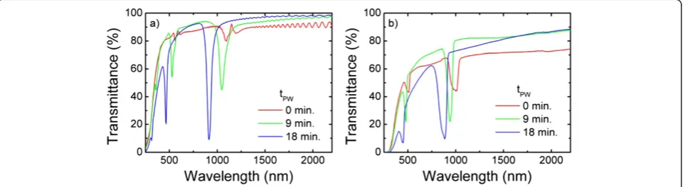
begins to occur with the reduction of the voltage. How-ever, the branching is frustrated by the immediate increase of the voltage as it reaches the 20-V value with the conse-quent single-pore development further into the next cycle. The effect of applying different number of cycles to obtain the NAA-based DBR can be deduced from the transmittance spectra shown in Figure 2. The plots show
the spectra for a sample produced with NC= 50 and
Tanod= 9°C (a) and a sample withNC= 150 andTanod= 7°C (b) after different pore-widening times (tPW= 0, 9, and 18 min). All the spectra show two stop bands (spec-tral ranges with reduced transmittance): the first-order stop band at higher wavelengths and also a second-order stop band at half of the wavelength of the first one. It is interesting to remark that the spectra for the
as-produced samples (tPW= 0 min) show irregular stop
bands, especially for the sample withNC= 50 that shows
even a local transmittance maximum at 1,152 nm. This is usual in NAA-based DBR obtained with a cyclic voltage [16] and is explained by the fact that porosity depends weakly on anodization voltage, and in consequence, volt-age variations create morphology changes in the pores as they grow but small changes in porosity. Nevertheless, it is worth to note that the stop band for the as-produced 150-cycle sample shows a more pronounced decrease in the transmittance within the stop band. Thus, even though the refractive index contrast is small, a higher number of cycles and the corresponding higher number of cycle interfaces contribute to enhance the photonic stop band properties. The spectra for the samples after some pore widening show clearly defined stop bands with decreasing central wavelength for increasing pore widening time. Additional file 1: Table S1 summarizes the values of central wavelength and stop band width of the spectra. By comparing the ranges in the spectra not corresponding to a stop band, it can be concluded that the transmittance forNC= 150 is lower than forNC= 50. This difference can be attributed to scattering losses caused by the irregular interfaces between each cycle. Finally, there is a clear difference between the central wavelength of the stop bands, which is lower for the sample produced at the lower temperature,NC= 150 andTanod= 7°C.
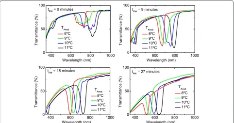
In order to evaluate more precisely this dependence of the stop band central wavelength with the temperature, Figure 3 shows the transmittance spectra for samples
produced with temperatures Tanod= 8, 9, 10, and 11°C
[image:3.595.57.290.89.282.2]and after different times of pore widening,tPW= 0, 9, 18, and 27 min. The spectra show similar trends as the observed in Figure 2: for the as-produced samples, the spectra show truncated stop bands that become better defined with the pore-widening process. At the same time, the pore widening causes a decrease in the central wavelength as it decreases the overall effective refractive index of each cycle in the DBR. Additional file 1: Table S2 reports the values of stop band central wavelength and stop band width for the spectra. The spectra in Figure 3 show that the main influence of the anodization
[image:3.595.59.541.584.716.2]Figure 1SEM cross-section picture of NAA-based DBR sample obtained with Q0= 0.5 C, 50 cycles, andTanod= 9°C.‘a’interfaces limiting one cycle,‘b’pore with conical shape,‘c’beginning of a pore branching corresponding to a decreasing anodization voltage, ‘d’frustrated branch as the voltage increases again, and‘e’surviving pore growing in the subsequent cycle.
temperature is in the stop band central wavelength, while other features such as the depth of the stop band transmittance minimum or the difference in shape ob-served for the as-produced samples are less influenced byTanod.
The dependence of the central wavelength with the anodization temperature is summarized in Figure 4, where the different central wavelengths of the first-order stop band are plotted as a function of the pore-widening time. The data in Figure 4 demonstrate that by a precise control of the temperature and of the pore-widening
[image:4.595.57.540.89.343.2]time, the stop band central wavelength can be modulated between 500 and 820 nm. The curves for the different temperatures show the same behavior, what indicates that carrying the anodization at a different temperature does not influence the pore-widening rate in the subsequent pore-widening process. It is also important to mention that the intervals between the curves in Figure 4 are constant, what indicates that the shift of the central wavelength with the temperature is uniform with an esti-mated average value of 42.5 nm/°C (see Additional file 1: Figure S2). Table 1 shows the average stop band width for the different pore-widening times and the corresponding standard deviation. This average and standard deviation for a given pore-widening time are obtained considering all the values for the different temperatures. The results show that there is a small dispersion in stop band width
Figure 3Comparison of the spectra of samples obtained at different anodization temperatures and after different pore-widening times.
[image:4.595.57.290.527.694.2]Figure 4Evolution of central wavelength of the first stop band as function of pore-widening time for different anodization temperatures.
Table 1 Average stop band width and corresponding standard deviation as a function of the pore-widening time
Pore-widening time (min)
Average stop band width (nm)
Stop band width standard deviation (nm)
0 103 22
9 68 14
18 50 5
27 46 6
[image:4.595.304.539.613.690.2]for the different temperatures. Since the stop band width depends basically on the refractive index contrast that can be achieved within a cycle, it can be concluded that the anodization temperature has a small influence in the refractive index contrast.
Conclusions
In this work, we analyzed the influence of the anodization temperature and of the number of applied voltage cycles on the photonic properties of NAA-based DBRs obtained by cyclic voltage anodization. In previous works, it was shown that DBR structures with stop bands can be ob-tained by the application of an anodization based in the repetition of voltage cycles between 20 and 50 V in 0.3 M oxalic acid. It was also shown that the application of a pore-widening step after anodization is crucial in order to obtain well-defined stop bands with low transmittance and high reflectance. In this work, these nanoporous structures have been obtained in the range of temperatures between 8°C and 11°C, for 50 and 150 applied voltage cycles and pore-widening times up to 27 min. The effect of these pa-rameters on the morphologic and photonic properties of the nanostructures has been studied by means of SEM and spectroscopic transmittance measurements.
The results show that 50 applied voltage cycles are enough to produce stop bands and that increasing the number of cycles has two opposite effects: on one hand, an enhancement of the photonic stop bands is observed, in particular specially for the case of the as-produced samples, which is much better defined for samples with higher number of cycles. On the other hand, scattering losses are observed in the spectra caused by the irregular interfaces between cycles observed in the SEM images. Such losses increase with increasing number cycles and the corresponding interfaces.
Increasing the anodization temperature produces a re-markable shift of the photonic stop band central wave-length, with a linear rate of 42.5 nm/°C. On the other hand, a change in anodization temperature does not in-fluence noticeably the obtained stop band widths or the rate of the subsequent pore widening. These three facts suggest that anodization temperature has a strong effect on the pore growth rate during anodization, but a small influence on the pore diameter or morphology. With this, it is also put into evidence that a precise control and stabilization of the temperature along the whole fabrica-tion process is crucial to ensure accuracy in the tuning of the photonic stop bands.
Additional file
Additional file 1:Applied cyclic anodization voltage, linear fits of the evolution of the stop band central wavelength, and central wavelength and width of the first-order stop band.Example of the
applied cyclic anodization voltage, linear fits of the evolution of the stop band central wavelength with the temperature for the different applied pore widening times, and central wavelength and width of the first-order stop band for the samples obtained with different number of cycles and different anodization temperatures.
Abbreviations
DBR:distributed-Bragg reflector; NAA: nanoporous anodic alumina; NC: number of anodization voltage cycles;Tanod: anodization temperature; tPW: pore-widening time; SEM: scanning electron microscopy.
Competing interests
All the authors declare that they have no competing interests.
Authors' contributions
MMR, LFM, and JFB designed the experiment and analyzed and discussed the results. MMR fabricated the NAA-based DBR and performed the optical characterization. All authors redacted and revised the manuscript. All authors read and approved the final manuscript.
Acknowledgments
This research was supported by the Spanish Ministerio de Economía y Competitividad through the grant number TEC2012-34397 and the Generalitat de Catalunya through the grant number 2014-SGR-1344.
Received: 16 May 2014 Accepted: 16 July 2014 Published: 21 August 2014
References
1. Lee W:The anodization of aluminum for nanotechnology applications. JOM2010,62:57–63.
2. Sulka GD:Nanostructured Materials in Electrochemistry.Weinheim, Germany: Wiley-VCH Verlag GmbH & Co. KGaA; 2008:1–116.
3. Ingham CJ, ter Maat J, de Vos WM:Where bio meets nano: the many uses for nanoporous aluminum oxide in biotechnology.Biotechnol Adv2012, 30:1089–99.
4. Santos A, Kumeria T, Losic D:Nanoporous anodic aluminum oxide for chemical sensing and biosensors.TrAC Trends Anal Chem2013,44:25–38. 5. Pallarés J, Marsal LF, Ferré-Borrull J, Santos A, Formentin P:Quasi-ordered
P3HT nanopillar-nanocap structures with controlled size.Mater Lett2010, 64:371–374.
6. Kato T, Hayase S:Quasi-solid Dye sensitized solar cell with straight Ion paths.J Electrochem Soc2007,154:B117.
7. Santos A, Vojkuvka L, Pallarés J, Ferré-Borrull J, Marsal LF:Cobalt and nickel nanopillars on aluminium substrates by direct current electrodeposition process.Nanoscale Res Lett2009,4:1021–1028.
8. González-Díaz JB, García-Martín A, Armelles G, Navas D, Vázquez M, Nielsch K, Wehrspohn RB, Gösele U:Enhanced magneto-optics and size effects in ferromagnetic nanowire arrays.Adv Mater2007,19:2643–2647.
9. Masuda H, Fukuda K:Ordered metal nanohole arrays made by a two-step replication of honeycomb structures of anodic alumina.Science (80-) 1995,268:1466–1468.
10. Lee W, Ji R, Gösele U, Nielsch K:Fast fabrication of long-range ordered porous alumina membranes by hard anodization.Nat Mater2006, 5:741–7.
11. Macias G, Hernández-Eguía LP, Ferré-Borrull J, Pallares J, Marsal LF: Gold-coated ordered nanoporous anodic alumina bilayers for future label-free interferometric biosensors.ACS Appl Mater Interfaces2013,5:8093–8098. 12. Santos A, Kumeria T, Losic D:Optically optimized photoluminescent and
interferometric biosensors based on nanoporous anodic alumina: a comparison.Anal Chem2013,85:7904–7911.
13. Kumeria T, Rahman MM, Santos A, Ferré-Borrull J, Marsal LF, Losic D: Structural and optical nanoengineering of nanoporous anodic alumina rugate filters for real-time and label-free biosensing applications.Anal Chem2014,86:1837–1844.
15. Maksymov I, Ferré-Borrull J, Pallarès J, Marsal LF:Photonic stop bands in quasi-random nanoporous anodic alumina structures.Photonics Nanostructures - Fundam Appl2012,10:459–462.
16. Rahman MM, Marsal LF, Pallarès J, Ferré-Borrull J:Tuning the photonic stop bands of nanoporous anodic alumina-based distributed Bragg reflectors by pore widening.ACS Appl Mater Interfaces2013,5:13375–13381. 17. Macleod HA:Thin-Film Optical Filters.Boca Raton, Fl., U.S.A.: CRC Press Taylor;
2010.
18. Yeh P:Optical Waves in Layered Media.New York: John Wiley; 1988. 19. Wang B, Fei GT, Wang M, Kong MG, De ZL:Preparation of photonic
crystals made of air pores in anodic alumina.Nanotechnology2007, 18:365601.
20. Sulka GD, Hnida K:Distributed Bragg reflector based on porous anodic alumina fabricated by pulse anodization.Nanotechnology2012,23:075303. 21. Sakoda K:Optical Properties of Photonic Crystals.2nd edition. Berlin: Springer;
2005.
22. Joannopoulos JD, Meade RD, Winn JN:Photonic Crystals: Molding the Flow of Light.Princenton, N.J., USA: Princenton University Press; 1995.
23. Santos A, Alba M, Rahman MM, Formentín P, Ferré-Borrull J, Pallarès J, Marsal LF:Structural tuning of photoluminescence in nanoporous anodic alumina by hard anodization in oxalic and malonic acids.Nanoscale Res Lett2012,7:228.
24. Zheng WJ, Fei GT, Wang B, Jin Z, De Zhang L:Distributed Bragg reflector made of anodic alumina membrane.Mater Lett2009,63:706–708. 25. Santos A, Formentín P, Ferré-Borrull J, Pallarès J, Marsal LF:Nanoporous
anodic alumina obtained without protective oxide layer by hard anodization.Mater Lett2012,67:296–299.
26. Zheng W, Fei G, Wang B, De Zhang L:Modulation of transmission spectra of anodized alumina membrane distributed Bragg reflector by controlling anodization temperature.Nanoscale Res Lett2009,4:665–667.
doi:10.1186/1556-276X-9-416
Cite this article as:Ferré-Borrullet al.:Tuning nanoporous anodic alumina distributed-Bragg reflectors with the number of anodization cycles and the anodization temperature.Nanoscale Research Letters20149:416.
Submit your manuscript to a
journal and benefi t from:
7 Convenient online submission
7 Rigorous peer review
7 Immediate publication on acceptance
7 Open access: articles freely available online 7 High visibility within the fi eld
7 Retaining the copyright to your article