Tissue differentiation and bone regeneration in an
osteotomized mandible: a computational analysis of the
latency period
A. Boccaccio
1,2, P.J. Prendergast
2
, C. Pappalettere
1,D.J. Kelly
2 1Dipartimento di Ingegneria Meccanica e Gestionale, Politecnico di Bari, 70126, Bari, Italy 2
Trinity Centre for Bioengineering, Department of Mechanical and Manufacturing Engineering, Trinity College
Dublin, Ireland.
Address correspondence to: Dr. Daniel Kelly
Mailing Address:
Centre for Bioengineering,
Department of Mechanical Engineering, Trinity College Dublin,
Dublin 2, Ireland.
Contact Information:
Abstract
Mandibular symphyseal distraction osteogenesis is a common clinical procedure to modify the geometrical shape of the mandible for correcting problems of dental overcrowding and arch shrinkage. In spite of consolidated clinical use, questions remain concerning the optimal latency period and the influence of mastication loading on osteogenesis within the callus prior to the first distraction of the mandible. This work utilized a mechano-regulation model to assess bone regeneration within the callus of an osteotomized mandible. A 3D model of the mandible was reconstructed from CT scan data and meshed using poroelastic finite elements. The stimulus regulating tissue differentiation within the callus was hypothesized to be a function of the strain and fluid flow computed by the finite element model. This model was then used to analyse tissue differentiation during a fifteen day latency period, defined as the time between the day of the osteotomy and the day when the first distraction is given to the device. The following predictions are made: (i) the mastication forces generated during the latency period support osteogenesis in certain regions of the callus, and that during the latency period the percentage of progenitor cells differentiating into osteoblasts increases; (ii) reducing the mastication load by 70% during the latency period increases the number of progenitor cells differentiating into osteoblasts; (iii) the stiffness of new tissue increases at a slower rate on the side of bone callus next to the occlusion of the mandibular ramus which could cause asymmetries in the bone tissue formation with respect to the middle sagittal plane. Although the model predicts that the mastication loading generates such asymmetries, their effects on the spatial distribution of callus mechanical properties are insignificant for typical latency periods used clinically. It is also predicted that a latency period of longer than a week will increase the risk of premature bone union across the callus.
Keywords: Mechanobiology; Mandibular distraction osteogenesis; Orthodontic devices; Tissue
1. Introduction
The problems of posterior buccal nonocclusion (a skeletal deficiency where occlusion cannot occur on both sides of the posterior region of the oral cavity), mandibular anterior crowding and narrowed arches are usually solved in growing patients by tooth extraction or expansion techniques. However expansion of the anterior dentoalveolar structures is often unstable and tends to relapse towards the original dimension [22, 40]. Mandibular transversal distraction osteogenesis may solve transverse mandibular deficiency problems. With this clinical procedure the mandibular geometry is definitively changed. Distraction osteogenesis facilitates osteo-synthesis via distraction of the existing bone tissue. Bone elongation begins when the callus formed after the osteotomy is slowly distracted. Tensile stresses acting on the bone tissue are thought to stimulate bone re-growth in the direction of applied forces [14]. Mandibular transversal distraction osteogenesis is therefore based on the “law of tension-stress” proposed by Ilizarov [26], which states that progressive tensioning of vital tissues will create stresses that induce and maintain growth and proliferation of the tissue. This hypothesis is supported by the results of Kaspar et al. [29], who reported greater mitogenic activity in cells from a distracted bone callus compared to a normal bone callus.
complications may arise such as fibrous union, non-union, tooth loss and periodontal defects [13]. On the other hand, too long a latency period may substantially increase the risk of premature bone union [27], which can hinder the subsequent expansion process.
A number of studies have used the finite element (FE) method to investigate the mechanics of mandibular distraction osteogenesis [5, 7, 8, 11, 32]. Loboa et al. [35] used a FE approach to study tissue differentiation at different stages of mandibular distraction osteogenesis in a rat model. By comparing the predicted levels of stresses and strains to histological findings, they showed that tensile strain up 13% in the bone callus corresponded to regions of new bone formation and regions of periosteal hydrostatic pressure with magnitude less than 17 kPa corresponded to locations of cartilage formation. However, to date, no clear mechano-biological explanation has been given for the influence of (i) the length of the latency period, and (ii) the magnitude of mastication loading, on osteogenesis within the callus prior to mandibular distraction ostengenesis.
investigation of the latency time and its effects on the bone regeneration process will be carried out. We hypothesize that the mechanics of the mastication will influence the biophysical stimulus within the callus following the osteotomy to such a degree that it will alter the spatial distribution of the callus mechanical properties. An asymmetric distribution of the callus mechanical properties during the latency period is undesirable because in the subsequent distraction process an asymmetric widening of the mandibular arch – with respect to the middle sagittal plane – can occur. Investigating whether or not the changing the length of the latency period, or reducing the mastication loading, will improve the regeneration in the callus are important questions, that can be difficult to answer experimentally, and computational tools such as that presented here are becoming increasingly important in pre-operative planning.
2. Materials and methods
2.1. Mechano-regulation algorithm
The dispersal of marrow derived mesenchymal stem cells (MSCs) throughout the bone callus can be described using a diffusion equation:
c
D
t
c
2∇
=
d
d
(1)
where c denotes the concentration of MSCs in a given volume and D is the diffusion coefficient. The parameter of Eqn. 1 (i.e. the D diffusion coefficient) was set so that the complete cell coverage in the callus is achieved two weeks after the osteotomy.
As MSCs disperse from the bone marrow throughout the bone callus, the only assumed cell source in this model, they will differentiate into different cell phenotypes based on the value of a biophysical stimulus S. Following Prendergast et al., [43], if γ is the octahedral shear strain and v
b
v
a
S
=
γ
+
(2)a and b being empirical constants [25], where a=3.75% and b=3µms-1. Depending on the value of S, each cell changes phenotype (regardless of its current phenotype) such that:
⇒ < < ⇒ < < ⇒ < < ⇒ < < ⇒ > resorbtion bone q S formation tissue bone mature and osteoblast q S q formation tissue bone immature and osteoblast S q formation tissue eous cartilagin and e chondrocyt p S formation tissue fibrous and fibroblast p S if resorb mature resorb mature 0 1 1 (3)
where qmature, qresorb and p represent boundaries of the mechano-regulation diagram for tissue
differentiation. Their values are taken to be the same as those utilized by Lacroix and Prendergast [33] and Kelly and Prendergast [30] (qresorb = 0.01, qmature = 0.53, p = 3).
2.2. Development of rate equation for material properties
Previous models of tissue differentiation have assumed a rapid differentiation from one tissue type to another, and described the subsequent change in the material properties of the tissue using a simple rule of mixtures [33, 30]. In order to better describe the temporal changes in tissue stiffness as healing progresses within the osteotomized region, it is assumed that the Young’s modulus of all tissues within the callus increase exponentially with time. The equation describing the variation of the Young’s modulus is of the form:
t i i i
e
K
E
=
γ⋅ (4)where Ei represents the Young’s modulus for tissue phenotype i (where i is either fibrous tissue,
cartilage, immature or mature bone), t is the time and Ki and γi are two parameters regulating the
of tissue phenotype i increases, in 75 days from the initial value of 0.2 MPa, typical of granulation tissue, to the final values reported in Table 1. The same time scale was set for the maturation of fibrous and cartilaginous tissue.
After the calculation of the new tissue phenotype and of the number of the MSCs invading the domain, the algorithm evaluates the mechanical properties for every element based on the exponential law (Eqn. 4) and a simple rule of mixtures. The material properties of every element were calculated as an average of the material properties of ten previous predicted tissue phenotypes. For example, if E is the average Young’s modulus for a particular element for the ten previous iterations and if c is the concentration of MSCs in a given volume in the iteration iter evaluated with Eqn. 1, then the Young’s modulus for that element and for the next iteration iter+1 will be given by:
(
)
n granulatio E c c c E c c iterE + = ⋅ + − ⋅
max max
max ) 1
( (5)
and ) ( 10 1 10 ni E E p p ni i
∑
+ == (6)
where cmax is the maximum concentration of MSCs which may occupy any one element domain, Egranulation is the Young’s modulus of the granulation tissue, ni is the number identifying the iteration,
p is the number identifying the tenth last iteration and Ei is the value of the Young’s modulus as
2.3. Generation of the finite element model
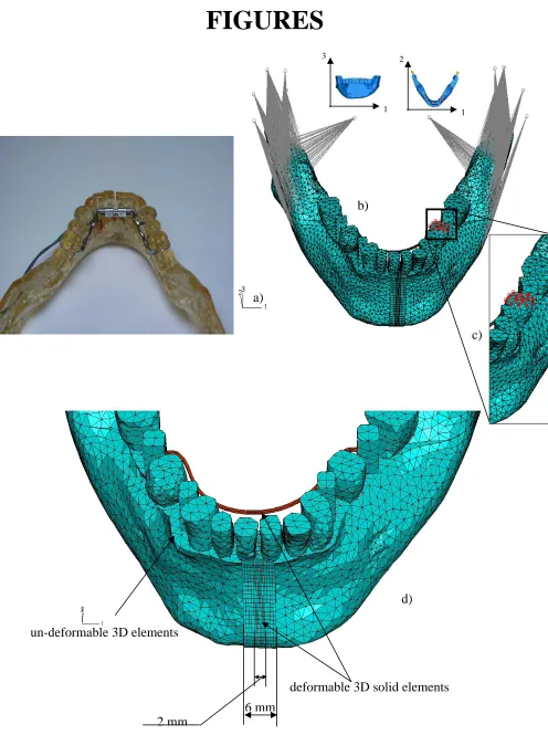
A 3D model of human mandible (see Fig. 1a) has been reconstructed from CT scan data and the processing of the CT files was made by means of the Mimics® Version 7.2 software (Materialise Inc.). The model also includes an orthodontic distractor tooth-borne device. The distractor consists of one band on the first mandibular molar, and one band on the first mandibular premolar, on both sides of the arch. Bands are steel rings connected by a 1.1 mm diameter stainless steel wire and a screw positioned behind the lower incisors.
Since the stiffness of the mandibular bone is orders of magnitude greater than the callus, it is possible to model the portion of bone and of the device far from the osteotomized region as a rigid body. Conversely, the portions of the bone, of the bone callus and of the device near to the middle sagittal plane were modelled with 3D deformable elements, i.e. poroelastic elements C3D8P (8 node trilinear displacement and pore pressure; 8 gauss points; active degrees of freedom u1, u2, u3
and pore pressure) for the bone and the bone callus and standard hexahedral elements C3D8 (8 node linear brick; 8 gauss points; active degrees of freedom u1, u2, u3) for the distraction device. With this
strategy we reduce the computational cost of the analysis without introducing significant alterations with respect to the anatomo-physiological behaviour of the mandibular district. The FEM consists of about 12000 3-node un-deformable triangular elements (see Fig. 1b) and 5432 8-node hexahedral elements for meshing the osteotomized region and the deformable portion of the distractor device (Fig. 1d).
order to connect rigidly the deformable portions of the bone and of the device to the rigid ones. Preliminary numerical tests have been performed in order to evaluate the sensitivity of the results obtained with this model to the bone surrounding the callus. Simplified prismatic models of the bone-callus-bone structure shown in Fig. 2a were built with increasing thickness of the portion of the model representing the bone. The sensitivity of the strain and of the pore fluid velocities to the length of the bone was investigated for loading conditions similar to those acting on the bone callus during the mastication phase. It was found that if the bone thickness becomes three times as large as the thickness used in this study, negligible differences (in strains and in fluid flow velocities) arise. Also, preliminary convergence analyses have been performed on the bone callus model, in order to make the model as much as is possible grid independent.
2.4. Material properties
The bone callus and adjacent bone tissue were modelled as poroelastic materials. The cortical bone was modelled as an orthotropic material (E11=20 GPa, E22=12 GPa, E33=14 GPa; ν12=0.36, ν13=0.33, ν23=0.2), the principal material directions and elastic moduli of which have been taken from Schwartz-Dabney and Dechow [48]. The poroelastic properties have been assumed isotropic with a permeability of 1.10-17 m4/Ns [15] for the cortical bone and 1.05.10-9 m4/Ns [41] for the cancellous bone. The material properties used for all other tissues are the same as used in previous models [33], and are listed in Table 1, while the principal material directions (1, 2, 3) are shown in Fig. 2b.
2.5. Finite element analysis and boundary conditions
modelled by constraining these reference points to three fixed points by means of spring elements aligned to the coordinate system. In this way, the mandible can rotate about an axis defined by the line connecting the two condyles and translate along the coordinate directions.
Boundary condition (ii) models the mastication phase. The action of the most important muscles involved in the mastication process, the masseters, the temporals and the pterygoid
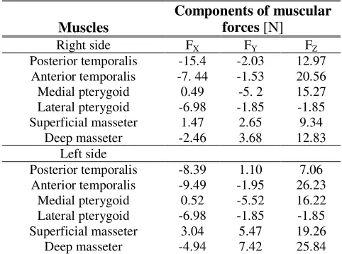
muscles, are included. Loads are applied at points where muscles are inserted into the mandibular bone. Coupling constraints allowed us to distribute the force exerted by each muscle on the mandibular surface where they act. Two different mastication loads have been applied on the model: a full mastication load where the values of forces of each muscle are the same as those used in a previous work [7] (see Table 2) and evaluated by Faulkner et al. [17]; secondly a reduced mastication load where the forces developed by each muscle have been reduced by 70%. For each of these two mastication loadings, two different ramp loading periods were investigated, in order to simulate the patient masticating quickly or slowly. In the first simulation the loading is ramped rapidly over a 1 second period, and in the second simulation the loading is ramped over a 120 second time period.
Boundary condition (iii) simulates the unilateral occlusion on one tooth on the left mandibular arm (see details in Fig. 1c). The action of chewing on the mandibular arch is modelled by constraining, with simple-supports preventing u3-displacements, the second premolar. In other words, we simulated the unilateral occlusion by preventing the displacements along the direction 3 for the second premolar. Typically the mastication process occurs on one side of the mandibular arch, however in the initial stages of mastication it is reasonable to assume that the occlusion occurs on one tooth in particular.
2.6. Implementation of mechano-regulation model
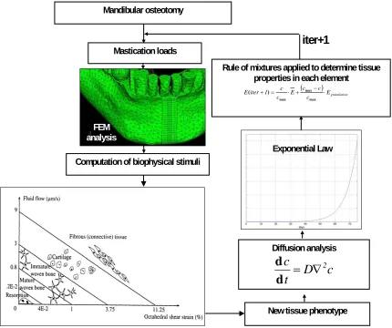
Eqn. 1 was solved using a mass diffusion element in Abaqus (Hibbitt, Karlsson & Sorensen, Powtucket, RI, USA). The equations describing cell dispersal and differentiation, is implemented into an algorithm, a graphical summary of which is depicted in Fig. 3. Mastication loads acting on the mandibular bone produce strain and fluid flow within the bone callus. The computation of the biophysical stimulus S is done by using the octahedral shear strain and the velocity fluid flow calculated by the finite element model at the end of the ramp loading. The algorithm computes the biophysical stimulus S (Eqn. 2) and according to Eqn. 3 the new tissue phenotype. At this point, the diffusion analysis calculates the concentration of MSCs invading every element. Based on the exponential law (Eqn. 4) and on a rule of mixtures (Eqns. 5-6) the algorithm evaluates the mechanical properties for every element for the next iteration. Each iteration corresponds to 4.8 hours, that is, the diffusion equation (Eqn. 1) computes the change of cells concentration occurring every 4.8 hours. Therefore, with 75 iterations a period of 15 days is covered, with 5 iterations corresponding to one day.
In order to evaluate how the bone callus mechanical properties distribute with respect to the middle sagittal plane the symmetry coefficient CS was introduced. Let Eleft and Eright be the Young’s
modulus along the latero-lateral direction (i.e. direction 1 in Fig. 1b) of the left and of the right hand side of callus respectively (for more details see Appendix A). If Eequivalent is the Young’s modulus in
the same 1-direction for the whole bone callus model, the CS symmetry coefficient is given by:
100 E
E E C
equivalent right left
S ⋅
−
=| | (7)
The symmetry coefficient CS has been calculated for a time period of 40 days. It is clear that the
symmetry coefficient CS could provide useful informations for the clinicians. A too high value of CS
Computations are performed on a HP XW4100 workstation with a single 2.8 GHz Intel Pentium IV CPU and 512 Mb of RAM memory. The computation time is about 30 minutes for each iteration.
3. Results
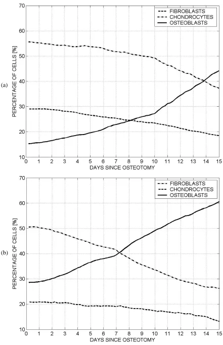
In the case of full mastication loading applied over a ramp period of 120 seconds, the percentage of MSCs within the entire callus differentiating into osteoblasts increases during the latency period, while the percentage of chondrocytes and fibroblasts within the callus decreases (Fig. 4a). Reducing the applied mastication loading is predicted to increase the number of progenitor cells differentiating into osteoblasts and reduce the number of progenitor cells differentiating into chondrocytes. Reducing the ramp time to 1 second is not predicted to have a major effect on the overall differentiation process. In general, the fluid flow within the callus increases and the strain decreases, with a slight overall increase in the biophysical stimulus S within the callus. This results in a slight increase in soft tissue formation and a corresponding decrease in bone formation at both loading magnitudes (see Fig. 4b).
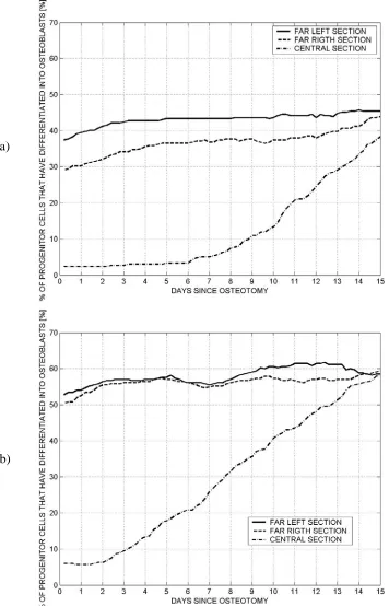
The percentage of MSCs differentiating into osteoblasts is predicted to be greater on the far left side (FLS) compared to the far right section (FRS) (Fig. 5) for the full mastication load. This difference becomes negligible if the mastication loads acting on the mandible are reduced.
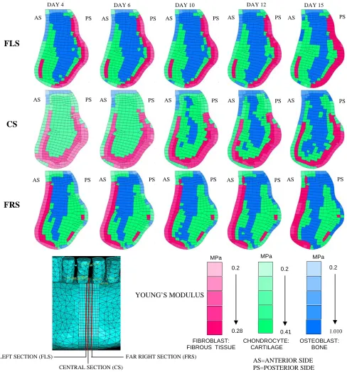
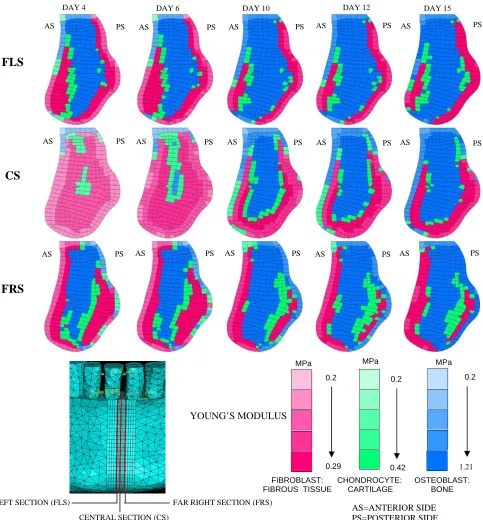
predicted on the anterior side of the far right section (Fig. 6 & 7). In general, it is predicted that applying a full mastication load will lead to new bone formation by both intramembranous and endochondral ossification (Fig. 6), while primarily intramembranous ossification with little cartilage formation is predicted with reduced mastication loading (Fig. 7).
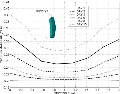
The change in Young’s modulus through the thickness of the callus can be determined by averaging the Young’s modulus of each layer of elements that make up the callus model. The Young’s modulus is lowest in the centre of the callus (Fig. 8). The Young’s modulus of the whole callus increases with time as MSCs invade the region and the new tissues forming within the callus begin to stiffen. Furthermore, in the days following the osteotomy the CS symmetry coefficient (see
Methods section) is near to zero but, after the sixth-seventh day increases (Fig. 9). Only for very long latency periods (> 20 days) are significant asymmetries predicted in the mechanical properties of the callus. Greater asymmetries are predicted in the case when full mastication loads are applied for both120 seconds and 1 second ramp loading period.
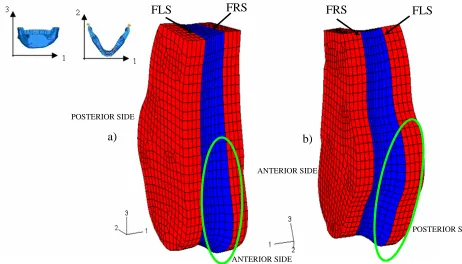
In order to investigate if premature bone bridging between the two sides of the fracture callus could hinder the subsequent distraction process, the amounts of new bone within the callus with a predicted Young’s modulus greater than 0.7 MPa were isolated (see Fig. 10 which illustrates the process of bone formation in the frontal plane 1-3 for the 120 second ramp loading). After seven days, portions of bone tissue linking the left with the right side of the callus are predicted to form in the case of reduced mastication loading, however this process is delayed slightly if full mastication loading is applied (Fig. 10). Similar results are predicted for the faster ramp loading (Fig. 11).
4. Discussion
Concerning the finite element model itself, we modelled the temporo-mandibular joint by combining coupling constrains and spring elements. In reality, the mechanics of this articulation is more complex [9], but nevertheless represents a reasonable approximation to reality. It is difficult to accurately quantify the poroelastic boundary conditions such as the pore pressure boundary conditions in such a model. It has been assumed here that pore pressure was zero on the external surface of the callus and that of the surrounding cortical bone, however this assumption would be invalid in the case of an intact periosteum. No account is made of the forces exerted by soft tissue envelop, which could play an important role in bone relapse. It is also worth noting that chewing is a dynamic task and therefore the assumption that the occlusion is always happening on one side and in one specific location could introduce errors in the computation of the tissue differentiation process. Furthermore, the values of force exerted by each muscle were taken from Faulkner et al.
[17] who measured them by using a symmetric recruiting of the muscles on both the controlateral and ipsilateral side, however there are limitations with this approach [46]. The periodontal ligament (PDL) was not included in the finite element model. The micro-movements produced by the PDL could have an influence on the biophysical stimulus S within the callus. The mandibular bone is also more complex than assumed here. It comprises, in addition to the cortical and trabecular bone, the alveolar bone and it is characterized by the presence of the roots, the alveolar sockets and the periodontal ligament. It spite of these limitations it should be noted that the same modelling of the boundary conditions etc. presented in this study was adopted in a previous model [7] where a good agreement was found between in vivo measurements of interdental distances and the corresponding distances predicted by the numerical model. Predicted stress peaks were also found to be consistent with those determined by Basciftci et al. [5].
respond differently to identical conditions due to genetic differences. Material properties and mechanical loading will vary from person to person, and even the callus within a single patient will experience mechanical loading that changes with time. No account has been made in the present model for inter-patient variability or for what effect uncertainty in loading etc. has on the tissue differentiation process. The reasons for this are two-fold. Firstly, variations, for example, in the boundaries used in the mechano-regulation diagram (Eqn. 3) due to genetic variation were not considered as to do so could lead to suggestions of tweaking these boundaries in order to match model predictions to experimental findings. Secondly, the computational cost of running these simulations is very large, and introducing statistical variation would be prohibitively costly. As computational power increases, it will be possible to run such simulations.
seconds. In this case, a distraction force of 35.8 N and 35.1 N was predicted in the case of full mastication loads for a ramp loading time of 120 seconds and 1 second respectively, while a distraction force of 41.3 N and 37.7 N was predicted in the case of the reduced mastication loading for a ramp loading time of 120 seconds and 1 second respectively. It appears that the values of forces predicted by the computational model in the case of full mastication loadings fall within the range mean ± standard deviation found by Robinson et al. [45], while the values of force computed in the case of the reduced mastication loading are higher than found experimentally. Further validation of such evolution equations will be required in the future.
Certain modelling assumptions adopted in this study are therefore different to those adopted by Lacroix and Prendergast [33] and others. In that study, in order to account for the delay between the time that stimuli first act on the cells and the process of differentiation into a new phenotype, the material properties of an element in their model were calculated as an average of the 10 previously predicted tissue phenotypes. This approach was further developed here in order to account for the fact that mesenchymal cells not only require time to differentiate, but that the differentiated cell types require time to synthesise and remodel a new tissue. Indeed, a more precise formulation should account for the fact that the mechanical stimulus acting on the cells will also regulate the temporal change in tissue mechanical properties. The introduction of evolution equations describing the temporal changes in tissue properties as a function of the tissue type and of the biophysical stimulus would be a worthwhile addition to future models. Also the diffusion coefficient D used in this study is different with respect to that used in Lacroix and Prendergast [33]. In the latter work D
is set so that the MSCs cover totally the bone callus within 16 weeks which is the typical time for the tibial fracture healing. Here, a diffusion coefficient D was set such that the bone callus coverage by MSCs occurs in two weeks. To the author’s knowledge, no clear information is available in the literature about the dispersal rate of the MSCs within a mandibular fracture callus.
callus. However, in general cartilage tissue formation is not observed in vivo until late in the latency period, and the early predictions of cartilage formation by the model indicate that either the limitations of the model discussed earlier will need to be addressed to improve the validity of the mechano-regulation model, or that the fundamental hypotheses (Eqn 2 and 3) on which the model is based will have to be altered to more accurately predict tissue differentiation within membranous bones such as the mandible.
agreement with Conley and Legan [13] who suggest a latency period of seven days.
5. Conclusion
References
[1] Anderson CB (1967) Mechanics of fluids. In: Baumeister, T. (Ed.), Marks’ Saturated Handbook of Mechanical Engineers, pp. 3.48-3.76.
[2] Andreykiv A, Prendergast PJ, van Keulen F, Swieszkowski W, Rozing PM (2005) Bone ingrowth simulation for a concept glenoid component design. J Biomech 38:1023-1033.
[3] Armstrong CG, Mow VC (1982) Variations in the intrinsic mechanical properties of human articular cartilage with age, degeneration and water content. J Bone Joint Surg 64A:88-94.
[4] Aronson J: Mechanical factors generated during distraction osteogenesis. The International Society for Fracture Repair, Ottrot, France, April 1992
[5] Basciftci FA, Korkmaz HH, Iseri H, Malkoc S (2004) Biomechanical evaluation of mandibular midline distraction osteogenesis by using finite element method. Am J Orthod Dentofac 125:706-715. [6] Barbieri G, Barbieri CH, de Matos PS, Pelá CA, Mazzer N (2005) Ultrasonometric evaluation of the
healing of a transverse diaphyseal osteotomy in different periods. Experimental study in sheep tibiae. Acta Ortopedica Brasileira 13(2):61-67.
[7] Boccaccio A, Lamberti L, Pappalettere C, Carano A, Cozzani M (2006a) Mechanical behaviour of an osteotomized mandible with distraction orthodontic devices. J Biomech 39:2907-2918.
[8] Boccaccio A, Lamberti L, Pappalettere C, Cozzani M, Siciliani G (2006b) Comparison of different orthodontic devices for mandibular symphyseal distraction osteogenesis: a finite element study. Am J Orthod Dentofac, In Press.
[9] Beek M, Koolstra JH, Van Ruijven LJ, Van Eijden TMGJ (2000) Three-dimensional finite element analysis of the human temporomandibular joint disc. J Biomech 33:307-316.
[10] Carter DR, Blenman PR, Beaupré GS (1998) Correlations between mechanical stress history and tissue differentiation in initial fracture healing. J Orthop Res 6:736-748.
[11] Cattaneo PM, Kofod T, Dalstra M, Melsen B (2005) Using the finite element method to model the biomechanics of the asymmetric mandible before, during and after skeletal correction by distraction osteogenesis. Comput Methods Biomech Biomed Engin 8(3):157-65.
[12] Claes LE, Heigele CA (1999) Magnitudes of local stress and strain along bony surfaces predict the course and type of fracture healing. J Biomech 32:255-266.
[13] Conley R, Legan H (2003) Mandibular symphyseal distraction osteogenesis: diagnosis and treatment planning considerations. Angle Orthod73:3-11.
[14] Costantino PD, Friedman CD, Shindo ML, Houston CG, Sisson GA (1993) Experimental mandibular regrowth by distraction osteogenesis long term results. Arch Otolaryngol Head Neck Surg 119:511-516.
[15] Cowin SC (1999) Bone poroelasticity. J Biomech 32:217-238.
[16] Del Santo M, Guerrero CA, Buschang PH, English J, Samchukov L, Bell W (2000) Long-term skeletal and dental effects of mandibular symphyseal distraction osteogenesis. Am J Orthod Dentofac 118:485-493.
[17] Faulkner MG, Hatcher DC, Hay A (1987) A three-dimensional investigation of temporomandibular joint loading. J Biomech 20:997-1002.
[18] Gòmez-Benito MJ, Garcìa-Aznar JM, Kuiper JH, Doblaré M (2005) Influence of fracture gap size on the pattern of long bone healing: a computational study. J Theor Biol235:105-109.
[19] Guerrero CA, Contasti GI (1992) Transverse (horizontal) mandibular deficiency. In: Modern Practice in Orthognathic and Reconstructive Surgery (Bell, W.H. Editor). Saunders, Philadelphia (USA), pp. 2383-2397.
[20] Guerrero CA, Bell WH, Contasti GI, Rodriguez AM (1997) Mandibular widening by intraoral distraction osteogenesis. Br J Oral Maxillofac Surg 35:383-92.
[21] Halevy O, Krispin A, Leshem Y, McMurtry JP, Yahav S. Early-age heat exposure affects skeletal muscle satellite cell proliferation and differentiation in chicks. Am J Physiol Regul Integr Comp Physiol. 2001 Jul;281(1):R302-9
[22] Herberger RJ (1981) Stability of mandibular intercuspid width after long periods of retention. Angle Orthod 51:78-83.
[23] Hollis JM, Aronson J, Hofmann OE (1992). Differential loads in tissues during limb lengthening. Trans Orthop Res Soc 38: 14.
interface following total joint replacement. J Biomed Mater Res 16:911-927.
[25] Huiskes R, van Driel WD, Prendergast PJ, Søballe K (1997) A biomechanical regulatory model of periprosthetic tissue differentiation. J Mater Sci Mater Med 8: 785-788.
[26] Ilizarov GA (1989) The tension stress effect on the genesis and growth of tissues. Part I, the influence of stability of fixation and soft tissue preservation; Part II, the influence of the rate and frequency of distraction. Clin Orthop 238:249-285.
[27] Imola JM (2004) Craniofacial distraction osteogenesis. http://www.emedicine.com/ent/topic702.htm [28] Isaksson H, van Donkelaar CC, Huiskes R, Ito K (2006) Corroboration of mechano-regulatory
algorithms for tissue differentiation during fracture healing: comparison with in vivo results. J Orthop Res 24(5):898-907.
[29] Kaspar D, Neidlinger-Wilke C, Holbein O, Claes L, Ignatius A (2003) Mitogens are increased in the systemic circulation during bone callus healing. J Orthop Res 21:320-325.
[30] Kelly DJ, Prendergast PJ (2005) Mechano-regulation of stem cell differentiation and tissue regeneration in osteochondral defects. J Biomech 38:1413-1422.
[31] Kessler P, Neukam FW, Wiltfang J (2005) Effects of distraction forces and frequency of distraction in bony regeneration. Br J Oral Maxillofac Surg 43:392-398.
[32] Kofod T, Cattaneo PM, Dalstra M, Melsen B (2005) Three-dimensional finite element analysis of the mandible and temporomandibular joint during vertical ramus elongation by distraction osteogenesis. J Craniofac Surg 16(4):586-93.
[33] Lacroix D, Prendergast PJ (2002) A mechano-regulation model for tissue differentiation during fracture healing: analysis of gap size and loading. J Biomech 35:1163-1171.
[34] Loboa EG, Fang TD, Warren SM, Lindsey DP, Fong KD, Longaker MT, Carter DR (2004) Mechanobiology of mandibular distraction osteogenesis: experimental analyses with a rat model. Bone 34:336-343.
[35] Loboa EG, Fang TD, Parker DW, Warren SM, Fong KD, Longaker MT, Carter DR (2005) Mechanobiology of mandibular distraction osteogenesis: finite element analyses with a rat model. J Orthop Res 23:663-670.
[36] Luo XF, Luo XD, Wang XY. Thermal stress can inhibit proliferation of ECV304 cells. Chin J Traumatol. 2003 Feb;6(1):8-11.
[37] Meyer U, Meyer T, Wiesmann HP, Kruse-Lösler B, Vollmer D, Stratmann U, Joos U (2001) Mechanical tension in distraction osteogenesis regulates chondrocytic differentiation. Int J Oral Maxillofac Surg 30:522-530.
[38] Meyer U, Kleinheinz J, Joos U (2004) Biomechanical and clinical implications of distraction osteogenesis in craniofacial surgery. J Craniomaxillofac Surg 32:140-149.
[39] Mora G, Forriol F (2000) Mechanical analysis of the healing of different osteotomies fixed externally. Int Orthop 24:295-298.
[40] McNamara JG, Brudon WM (1993) Orthodontic and orthopaedic treatment in the mixed dentition. Ann Arbor (MI): Needham Press; pp. 131-145.
[41] Ochoa JA, Hillberry BM (1992) Permeability of bovine cancellous bone. Trans. of the 38th ORS, p. 162.
[42] Pauwels F (1960) Eine neue theorie über den einfluβ mechanischer reize auf die differenzierung der stützgewebe. Z Anat Entwickl. Gesch. 121, 478-515. Translated as A new theory concerning the influence of mechanical stimuli on the differentiation of the supporting tissues. In: Maquet, P., Furlong, R., (Eds) Biomechanics of the Locomotor apparatus, Springer, Berlin, 1980, pp. 375-407. [43] Prendergast PJ, Huiskes R, Søballe K (1997) Biophisical stimuli on cells during tissue differentiation
at implant interfaces. J Biomech 30:539-548.
[44] Richardson JB, Kenwright J, Cunningham JL (1992) Fracture stiffness measurement in the assessment and management of tibial fractures. J Clin Biomech 7:75-79.
[45] Robinson R, O’Neal PJ, Robinson GH (2001). Mandibular distraction force: laboratory data and clinical correlation. J Oral Maxillofac Surg 59: 539-544.
[46] Ross CF, Patel BA, Slice DE, Strait DS, Dechow PC, Richmond BG, Spencer MA (2005) Modeling masticatory muscle force in finite element analysis: sensitivity analysis using principal coordinates analysis. Anat Rec A 283(A): 288-299.
[47] Schaffer MB, Burr DB (1988) Stiffness of compact bone: effects of porosity and density. J Biomech 21:13-16.
human dentate mandible. Am J Phys Anthropol 120:252-277.
[49] Tepic S, Macirowsky T, Mann RW (1983) Mechanical properties of articular cartilage elucidated by osmotic loading and ultrasound. Proceedings of the National Academy of Sciences USA 80, 3331-3333.
[50] Uhthoff HK, Rahn BA (1981) Healing patterns of metaphyseal fractures. Clin Orthop160:295-303. [51] Weil TS, Van Sickles J, Payne J (1997) Distraction osteogenesis for correction of transverse
APPENDIX A
EVALUATION OF THE SYMMETRY COEFFICIENT
The callus consists of 8 layers of elements. Its axial stiffness along 1 direction can be described by schematizing the callus as a set of springs arranged in series. Each spring will have a length equal to the thickness of each layer. If E(Li), i={1, 2, 3, …,8}, is the mean value of the Young’s modulus
calculated in Li layer, and Eequivalent is the Young’s modulus in the 1 direction for the whole bone
callus model, the CS symmetry coefficient is given by:
100 | | ⋅ − = equivalent right left S E E E
C (A1)
where Eleft, Eright and Eequivalent are given by:
and where SL and STOT are the thickness of each layer of elements and of the entire model
respectively. Considering that SL=STOT/8, therefore Eqn. A2 can be rewritten as:
∑
∑
∑
= = = 8 1 8 5 4 1 ) ( 1 8 ) ( 1 4 ) ( 1 4 i equivalent i right i left L E E L E E L E E (A3)TABLES
Table 1. Material properties utilized in FEM analyses for the bone callus
Material Granulation tissue
Fibrous tissue Cartilage Immature bone
Mature bone
Young’ Modulus
[MPa] 0.2[33] 2[24] 10[33] 1000[33] 6000[12]
Permeability
[m4/Ns] 1*10 -14
[33] 1*10-14 [24] 5*10-15 [3] 1*10-13 [33] 3.7*10-13 [41]
Poisson’s Ratio 0.167 [33] 0.167[33] 0.167[33] 0.3[33] 0.3[33] Bulk Modulus Grain
[MPa] 2300
[1] 2300[1] 3400[49] 13920[15] 13920[15]
Bulk Modulus Liquid
[MPa] 2300[1] 2300[1] 2300[1] 2300[1] 2300[1] Porosity 0.8[33] 0.8[33] 0.8[33] 0.8[33] 0.8[33]
Table 2. Components of muscular forces on mandible
Muscles
Components of muscular forces [N]
Right side FX FY FZ
Posterior temporalis -15.4 -2.03 12.97 Anterior temporalis -7. 44 -1.53 20.56
Medial pterygoid 0.49 -5. 2 15.27
Lateral pterygoid -6.98 -1.85 -1.85 Superficial masseter 1.47 2.65 9.34
Deep masseter -2.46 3.68 12.83
Left side
Posterior temporalis -8.39 1.10 7.06 Anterior temporalis -9.49 -1.95 26.23
Medial pterygoid 0.52 -5.52 16.22
Lateral pterygoid -6.98 -1.85 -1.85 Superficial masseter 3.04 5.47 19.26
[image:26.612.103.361.335.515.2]Figure Legends
Figure 1. (a) Epoxy resin model; (b) mandible-distractor orthodontic device FEM model, illustrating the coordinate system and the boundary conditions used; (c) details of the unilateral occlusion on the second premolar; (d) Details of the osteotomized region and of the tooth borne device.
Figure 2. (a) FEM model of the osteotomized zone. Different regions and materials included in the model: (b) cortical bone, (c) cancellous bone, (d) fracture callus.
Figure 3. Schematic of the implemented mechano-regulation algorithm.
Figure 4. Phenotype of cells composing the bone callus for full mastication loading and for mastication loading reduced by 70 %: (a) mastication loading applied over a ramp period of 120 seconds; (b) mastication loading applied over a ramp period of 1 second.
Figure 5. Bone percentage on the Far Left Section (FLS), Far Right Section (FRS) and Central Section (CS) for a full mastication loading and for a mastication loading reduced by 70%. Mastication loadings are applied over a ramp period of 120 seconds.
Figure 6. Tissue differentiation and mechanical properties of the bone callus computed with the mechano-regulation algorithm. Full mastication loads are applied. Mastication loading is applied over a ramp period of 120 seconds.
Figure 7. Tissue differentiation and mechanical properties of the bone callus computed with the mechano-regulation algorithm. Mastication loads are reduced by 70%. Mastication loading is applied over a ramp period of 120 seconds.
Figure 8. Mechanical properties of the bone callus at different time steps. Full mastication loads are applied over a ramp period of 120 seconds. The value reported for each location along the section is an average value of the Young’s modulus computed over the entire transverse section.
Figure 9. Symmetry coefficient CS at different days since the osteotomy for full mastication loads
and for mastication loads reduced by 70%. The mastication loading is applied over a ramp period of either 120 seconds or 1 second.
Figure 10. 3D visualization of the bone regeneration process, where mastication loads are applied over a ramp period of 120 seconds. (a) Full mastication loads are applied. (b) Mastication loading reduced by 70 % are applied.
FIGURES
1 3
1 2
b)
c)
a)
un-deformable 3D elements
6 mm
2 mm
deformable 3D solid elements
d)
Figure 1
. (a) Epoxy resin model; (b) mandible-distractor orthodontic device FEM model, illustrating
the coordinate system and the boundary conditions used; (c) details of the unilateral occlusion on the
Figure 2
. (a) FEM model of the osteotomized zone. Different regions and materials included in the
model: (b) cortical bone, (c) cancellous bone, (d) fracture callus.
b) c)
a)
1 2 3
Mastication loads
Computation of biophysicalstimuli
FEM analysis
Newtissuephenotype
Rule of mixtures applied to determine tissue properties in each element
( )
n granulatio
E c
c c E c
c 1 iter
E + = ⋅ + − ⋅
max max max
) (
Exponential Law
Diffusion analysis
c
D
t
c
=
∇
2d
d
iter+1
[image:30.595.110.540.124.484.2]Mandibular osteotomy
FLS
CS
FRS
DAY 4 DAY 6 DAY 10 DAY 12 DAY 15
PS PS
AS
AS PS AS PS AS PS AS
PS
AS AS PS AS PS AS PS AS PS
PS AS
AS PS PS AS
PS AS
AS PS
MPa MPa
MPa
FAR LEFT SECTION (FLS)
0.2
0.2 0.2
YOUNG’S MODULUS
0.28 0.41 1.010
CHONDROCYTE: CARTILAGE FIBROBLAST:
FIBROUS TISSUE
OSTEOBLAST: BONE
FAR RIGHT SECTION (FRS)
[image:31.595.59.547.86.609.2]AS=ANTERIOR SIDE PS=POSTERIOR SIDE CENTRAL SECTION (CS)
FLS
CS
FRS
DAY 4 DAY 6 DAY 10 DAY 12 DAY 15
PS PS
AS
AS PS AS PS AS PS AS
PS
AS AS PS AS PS AS PS AS PS
PS AS
AS PS PS AS
PS AS
AS PS
MPa MPa
MPa
FAR LEFT SECTION (FLS)
0.2
0.2 0.2
YOUNG’S MODULUS
0.29 0.42 1.21
FIBROBLAST: FIBROUS TISSUE
CHONDROCYTE: CARTILAGE
OSTEOBLAST: BONE
FAR RIGHT SECTION (FRS)
[image:32.595.63.546.85.605.2]AS=ANTERIOR SIDE PS=POSTERIOR SIDE CENTRAL SECTION (CS)
FRS
FLS
FRS
FLS
POSTERIOR SIDE
b)
ANTERIOR SIDE
POSTERIOR SIDE ANTERIOR SIDE
[image:33.595.86.548.112.376.2]a)
(a)
[image:34.595.108.464.72.626.2](b)
(a)
[image:35.595.89.530.70.752.2](b)
Figure 9
. Mechanical properties of the bone callus at different time step. Full mastication loads are
applied.
FULL MASTICATION LOAD
REDUCED MASTICATION LOAD
Figure 11
: 3D visualization of the tissue formation within the callus. Only elements containing
osteoblasts are included. LHS: full mastication loading. RHS: mastication loads reduced by 70%.
DAY 6 DAY 6
1.010
0.200
1.210
0.200
1
2
3
2
3
DAY 8 DAY 8
3
2
1
DAY 10 DAY 10
Figure 12
. 3D visualization of the bone regeneration process. Full mastication loads are applied.
DAY 6DAY 5 DAY 7
1.010
0.70
DAY 8 DAY 9
1 2
3
1
3
2
Figure 13
. 3D visualization of the bone regeneration process. Mastication loads are reduced by 70%.
DAY 6DAY 5 DAY 7
DAY 8 DAY 9
1.210
0.700
1 2
3
1