Iiïil
A ONE DIMENSIONAL XENON
liPSill
! i
ÌÌ
T R A N S I E N T pROGRAMME
1538
« i
FOR BOILING NUCLEAR REACTORS
í!'íti¿tf¡j
wWr
■m
H
*fflåil. JUS
hr
Toint Nuclear Research Centre
Reactor Physics Department
Ispra Establishment Italy
M P M N I
Reactor Theory and Analysis
mkää^i-t-tSM
;^ w f c w f t ; i ï % ^ ™ W-WK'« WC:
LEGAL N O T I C E
is document was prepared under the sponsorship of the
Commission of the European Communities.
. , , , .
,
<tit* ■
¡MvliSviHlilklffr
Neither the Commission of the European Communities, its
contractors nor any person acting on their behalf :
áEF
make any warranty or representation, express or implied, with
respect to the accuracy, completeness, or usefulness of the
information contained in this document, or that the use of any
information, apparatus, method, or process disclosed in this
document may not infringe privately owned rights ; or
at the price of F.Fr. 7.75 B.Fr. 70.— DM 5.10 It.Lire 870.— Fl. 5.10
This report is on sale at the addresses listed on cover page 4
When ordering, please quote the EUR number and the title,
which are indicated on the cover of each report.
Printed by L. Vanmelle, Ghent
Luxembourg, »*·—*
embourg, March 1971
·"»"
StI IfflBK^li-â^yjf^ î
WÊ
3£8 Í
»li i i
βί§Ρ%
iiilÜI
vm¡¿ \\m »il·. Miti Π H*Míit4Sw>c Æ ν?*, u.« .* .»^»'jLWlíri^iwn
II
EUR 4603 e
XBWR — A ONE D I M E N S I O N A L X E N O N T R A N S I E N T P R O GRAMME FOR BOILING N U C L E A R R E A C T O R S by G. F O R T I Commission of the E u r o p e a n Communities
J o i n t Nuclear Research Centre — I s p r a Establishment ( I t a l y ) Reactor Physics D e p a r t m e n t —■ Reactor Theory and Analysis Luxembourg, March 1971 — 46 P a g e s — B.Fr. 70.—
X B W R is a F O R T R A N p r o g r a m m e for the analysis of Xenon t r a n s i e n t s in axial geometry. I t couples a two g r o u p neutron diffusion calculation in plane g e o m e t r y with a two phase flow coo'ing channel calculation and the h e a t conduction in t h e typical fuel rod. The p r o g r a m m e allows to follow any given power time schedule, such as shutdown and r e s t a r t , daynight power variation etc., while the reactor is being k e p t critical by control rod movement, variable poison ing of the core, or coolant flow recirculation r a t e . The Xenon and Iodine concentrations variation is evaluated pointwise (up to 100 points'» by analytical solution for successive fixed time steps. A t the end
EUR 4603 e
XBWR — A ONE D I M E N S I O N A L X E N O N T R A N S I E N T P R O GRAMME FOR BOILING N U C L E A R R E A C T O R S by G. F O R T I Commission of the E u r o p e a n Communities
J o i n t Nuclear Research Centre — I s p r a E s t a b l i s h m e n t ( I t a l y ) Reactor Physics D e p a r t m e n t — Reactor Theory and Analysis Luxembourg, March 1971 — 46 P a g e s — B.Fr. 70.—
of each time step a new distribution of fluxes, power, voids and
temperatures is obtained, which is consistent with the reactor critical
condition as it is got by variation of the control parameter taking
into account the feedbacks. The new flux distribution is used as
input for Xenon and Iodine concentrations evolution in the next
time step.
EUR 4603e
COMMISSION OF THE EUROPEAN COMMUNITIES
X B W R
A ONE DIMENSIONAL XENON
TRANSIENT PROGRAMME
FOR BOILING NUCLEAR REACTORS
by
G. FORTI
1971
ABSTRACT
XBWR is a FORTRAN programme for the analysis of Xenon transients in axial geometry. It couples a two group neutron diffusion calculation in plane geometry with a two phase flow cooling channel calculation and the heat conduction in the typical fuel rod. The programme allows to follow any given power time schedule, such as shut-down and restart, day-night power variation etc., while the reactor is being kept critical by control rod movement, variable poison-ing of the core, or coolant flow recirculation rate. The Xenon and Iodine concentrations variation is evaluated pointwise (up to 100 points) by analytical solution for successive fixed time steps. At the end of each time step a new distribution of fluxes, power, voids and temperatures is obtained, which is consistent with the reactor critical condition as it is got by variation of the control parameter taking into account the feedbacks. The new flux distribution is used as input for Xenon and Iodine concentrations evolution in the next time step.
KEYWORDS
BOILING WATER REACTORS THERMAL CONDUCTIVITY
FORTRAN FUEL RODS
XENON CONTROL ROD DRIVES
TRANSIENTS POISONING
PROGRAMMING IODINE
NEUTRONS DISTRIBUTION
DIFFUSION FLUXES
GEOMETRY POWER
TWO PHASE FLOW VOIDS
3
-C O N T E N T S
1. Purpose 5
2. Nature of the programme 5
3. Control options θ
4. Output 9
5· Input form 10
6. Programme's performance, computer 10
specifications and user's directions
References 12
Appendix A 13
Appendix Β 29
5
-1 - Purpose *)
In BVR power reactors, the axial power shape is
strongly dependent on void distribution, and this
leads generally to fairly peaked and rather
asymmetric distributions. Another consequence is
that the power shape may be significantly altered
when the total power is changed. The effectiveness
of control rod banks may be significantly affected,
up to the point that in some instances it may even
change sign (actually insertion of a rod may cause,
through void feedback, a positive net reactivity
effect). In such situation, it is clear that Xenon
spatial effects may sometimes add up to the void
effects and lead to unacceptable power peaking
beyond the safety margin.
The problem facing the power plant operator
concerning Xenon is therefore not so much that of
stability in the theoretical sense, as that of
evaluating the actual consequences of specific
operations, and therefore the operative limitations
that spatial Xenon effects may introduce.
To cope with such problems a simulation by a somewhat
detailed model is needed, and this was the motivation
for the present XBWR code, which may anyway also be
used, with or without coolant channel, for classical
stability assessment.
2 - Nature of the programme
XBWR is built as a succession of stationary
calculations in which the criticality of the
reactor is restored, by means of the variation
of a control parameter (see control options)
after a given time step in which the Xenon and
Iodine concentrations at every point of a
discrete meshes are obtained by the analytical
solution of the equations :
4-
r
-
ϊχ{^Λ^Α)^ι
ι
oit
αν- *
in which the value of the fluxes and the initial
conditions for Xenon and Iodine concentrations
are
taken as given by the last time step.
When a problem is started, an initial criticality
search is made, which gives the starting conditions
as the equilibrium conditions for the reactor
with
Xenon and Iodine concentrations at equilibrium
for
the given power, and taking into account the fuel,
liquid coolant, and void fraction feedbacks
corresponding to the average channel conditions
evaluated by the code, according to the given
feedback coefficients. The search is made on λ ζ-~- -·
and the corresponding value found is multiplied ^
into all the ^)L coefficients so as to make
the reactor critical in the stationary condition.
After the initialization, a space dependent
perturbation may be introduced into Xenon and Iodine
concentrations and the transient is started. The
total power of the reactor may be changed at each
time
step, according to any given time schedule. If zero
power is specified for any given time interval, the
code will evaluate in a single jump the Xenon and
Iodine evolution during the shut down time.
The neutronic diffusion calculation is performed
by the finite differences direct method for the
two
group time dependent diffusion equations developed
for the Costanza series of dynamic codes, to which
the reader is referred for detailed information
(EUR 3633 e - EUR 596 e, see References).
There is one difference in the present code, in
the
fact that the fluxes calculated pointwise correspond
to the centre of each mesh, and not to the boundaries.
This has been found to be more quick and exact for
the problem at hand, where the calculation is finally
a stationary one. The criticality is considered
reached when the reciprocal of the period of the
reactor (without considering the delayed neutrons)
7
step, corresponding to a finite time increment, thereby
avoiding to iterate to convergence for each successive
control condition.
The thermohydraulic channel calculation is performed
according to the FRANCESCA one dimensional finite
difference model (EUR 4052 e and EUR 4241 e) which is
essentially based on Bankoff slip correlation for two
phase flow, and Bowring treatment of subcooled boiling.
The mesh description of the core is uniform, and the
same meshes apply to the neutronic and thermohydraulic
calculation. Upper and bottom reflectors of arbitrary
thikness may be represented in neutron calculation.
Three independent types of feedback are represented in
the code.
~
The liquid temperature feedback.o K is given as a
quadratic function of the difference between the
actual temperature in the point and a specified
reference temperature.
The fuel temperature (Doppler) feedback. It is
evaluated at each axial point as function of the
average temperature across the fuel rod at each
level. Three forms are available
/ ο_(/τ·
<JTK£?)
Nfoi
oVC ï. b. (<·
_ 4 ) ·£
( o< i s t h e void f r a c t i o n )
S K K s ο (\Γτ JTREP)
The void coefficient feedback. It is evaluated pointwise.
The form may be a quadratic in the void fraction
or a 20 point table may be given of oK
vas a function of ç<
In this latter case the code will interpolate linearly
in the table for a given value of c*
- 8
feed water according to the formula :
H U-
W fA
+-(.·*«-U/)* carry under ratio χ latent heat of
ύ*^* ""
fvaporization.
where u. is the ratio of feed water to total flow.
The enthalpy of feedwater is supposed to depend on power,
according to a quadratic formula:
3 - Control options
Three levels of control are available at each time step
to keep the reactor in critical conditions.
a) Recirculation flow control (optional)
If the corresponding option is checked, the recirculation
flow rate is varied between specified limits, to get
the reactor critical. The upper limit is fixed, while
the inferior limit is taken as a fraction of nominal
flow given by:
1. - a (1. - relative power).provided the value
obtained is not smaller than a fixed limit.
If the criticality cannot be achieved within the
prescribed limits, the control search is performed
by neutronic poisoning.
b) Neutronic poisoning control - One can choose between
two alternative ways: the neutronic poison may be
diluted in the whole reactor, varying the concentration
between 0 and an upper limit, or a control rod bank
may be represented as a movable boundary between
poisoned and unpoisoned regions. If the criticality
cannot be reached by the complete extraction of the
available poison, the control shifts to the power
reduction option; if the reactor is still overcritical
with fully inserted poison, the calculation stops
with a warning.
c) Power reduction control. If at a given time the
9
-power, a search is made to find out the maximum power
attainable in the current conditions. By this mean, one
can evaluate, for instance, the minimum time required to
reach full power after a shut down or a power reduction
at the end of the life of a fuel charge.
4 - Output
A flexible output routine (see input key) allows to
control the display of the principal items at the different
times, so as to obtain the relevant data without having
too many prints. An example of the output for the sample
case is given in appendix.
The output includes :
- a map of input data
- a description of the average coolant channel
- a first complete map of results referring to a preliminary
adjustment obtained by iterating neutronic and thermal
calculation with equilibrium Xenon concentrations. This
map has no physical meaning but may be useful when
convergence problems arise
- the record of the initial criticality search and the
complete map of the converged results :
- the prints referring to the transient: average values
and complete map of results at wanted times according
to the specifications of the user
The headings appearing in the output are interpreted as
follows :
P1 , P2 Fast and thermal fluxes
CI, CX Iodine and Xenon concentrations
HFL· Heat flux from the average fuel rod
DK 5 k feedback reactivity
VF Void fraction
TS Surface temperature of the cladding
TIC Inner cladding temperature
TL Liquid coolant temperature
TFMAX, AVTF Central (maximum) and average fuel temperatures
IT Time step numeral
INT Number of iterations for convergence
VINLET Inlet velocity of the coolant
REP Reciprocal of the period
- 10
5 - Input form
Many problems may be executed in one run. For every
problem the first input card is a title card, in which
any alphamerical information may appear in columns
from 7 to 70 included. This title will appear in the
output - a 1 in column 6 means that the problem is
the last of the run.
A vector of 3500 memory positions DATA (1) to DATA
(3500) contains all the data in floating point form
(Internal conversion is performed by the code when
needed). Since entire groups of memory positions are
zero, it is possible to read different sets of
significant data; each set must be preceded by a card
containing the integers Ki-j , Ki
2defining the first
and last datum of the set. Ki-j and Ki
2are given in
integer form adjusted to the right at columns 12
and 24. The last set of a problem is indicated by -1
in columns 1 and 2. The data of each set are all in
floating form (FORTRAN FORMAT E 12.8). Any number of
problems may be run in sequence and only the data
changing from the preceding problem need to be given.
A title card must be present for each problem. The
key to the input is given in appendix A.
6 - Programme's performance, computer specifications and
user's directions
The XBWR programme has been written in FORTRAN 360
and assembled in FORTRAN H level 0 under the IBM 360
O.S., and the total lenghth of the programme resulted
18A04 bytes.
Little can be said about the computer time required,
as it is strictly dependent on convergence rates and
thereby on physical conditions for the problem at hand.
An average case of 30 to 50 mesh points, with boiling
channel and recirculation flow control will take about
10 minutes of IBM 360 for 150 time steps. The speed
of calculation is very much increased when there is
no channel and no feedback.
11
The code has been extensively tested and generally performs
satisfactorily; the reader should anyway be aware that not
all the possible uses of the code, which embodies so many
options, have been explored and some difficulty may arise
in practical use. In our experience the difficulties can
be overcome, sometimes with some ingenuity on the part of
the user. Furthermore it should be remembered that the
convergence process of the iterative procedure that leads
to criticality is not theoretically proved. Actually, when
a rod bank search is made, there are cases in which the
process may not converge. Theese correspond to the
situations in which there is a maximum of reactivity for
a certain insertion of the bank, as it was mentioned in
the introduction. In such cases, a provision is made in
the logic of the iterative process to stop the iterations
and force, the insertion to a reasonable value. The
consequence is that the configuration of the reactor
reached by the code is not really critical. Such cases
are detected by observing that the reciprocal of the
period is higher than the convergence criterium, while
the number of iterations is smaller than the maximum.
This may happen also when the iterative process is not
really divergent, but the convergence is so slow that
the code forces the exit from the iteration process to
save machine time. The user should be aware that such
occurrences do not really impair the validity of the
results, as the only consequence is that the configuration
of the reactor is not perfectly critical, but the flux
shape is nearly correct. As in the calculations there is
no representation of delayed neutrons, a reciprocal of
the period of the order of 100, as the prompt neutron
lifetime is of the order of 1 0
- 4sec. corresponds to a
reactivity as low as 1000 pern.
- 12
References
EUR 3633 e The codes COSTANZA for the dynamics
of liquid-cooled nuclear reactors,
G.FORTI and E.VINCENTI, 1967
EUR 596 e Finite difference method for solving
the spatio-temporal diffusion equations
in the two-group approximation
R.MONTEROSSO and E.VINCENTI, 1964
EUR 4052 e A dynamci model for the cooling channels
of a boiling nuclear reactor with forced
circulation and high pressure level
G.FORTI, 1968
EUR 4241 e FRANCESCA, A dynamic program for boiling
cooling channels
APPENDIX A
INPUT KEY for XBWR code
TITLE CARD bbbbbb ANY TITLE to column 70 (1 in column 6 for the last problem of the run)
DATA n°
NAME
Description
Unit
Notes
1
2
3
4
ICORE
NRCORE
DT
IDST
6
7
I BAR
P0WFAC
IXE
Number of meshes (intervals) in the core
Number of regions of different composition in
the core
Time interval for calculation
Put 1. if initialization of the problem is
required
0. for a restarted problem
0. diffused poison control
1. Banked rods control-Rods entering as
coolant flow
-1. Banked rods control-Rods entering
apposite to coolant
Energy release per fission
0. Power time table given in input
1. After equilibrium a shut down is
imposed (see DATA (35))
-1. Iodine and Xenon concentrations perturbed
in input
Sec
up t o 94 ( 98 i f no reflector )
up t o 10
600.=10 minutes gives
very accurate results
u> IDATA n°
8
9
10
11
12
NAME
GAI
GAXE
DLI
DLXE
SAXE
13
17
18
19
SI
14
15
16
HCØRE
AREA
HR1
HR2
BU
DELT
Description
Iodine yeld per fission
Xenon 135 yeld per fission
Iodine decay constant
Xenon decay constant
C
yiiXenon microscopic capture cross
section (effective thermal) (no voids
see DATA 29 and 30 for void effects)
Total power of the reactor in the
nominal condition
Height of the core
Core horizontal cross section area
First reflector thickness (inlet of
coolant)
Second reflector thickness (outlet of
coolant)
2
Radial Buckling Β
Generally omitted (10
is chosen by
the code)
Time step for dynamic iterations
Unit
Notes
sec
sec
2
cm":
1
1
watt
cm
2
cm
cm
cm
2
cm
sec
put 0. if no reflector
has to be represented
A smaller time step
may be required for
convergence in some
cases. A wider time
step will speed up
calculations when
convergence is good.
DATA n°
NAME
Description
Unit
Notes
20
21
22
23
24
CHANN
Number of coolant subchannels (fuel
rods) in the core
IDOPP
Doppler feedback indicator:' , ,
<1.*Sk
ö α C r
f T D o P ) + b (T
fT.top)
7*·
4 , ^ S k ^
Ο(ΝΠ7~)[ΤΟΟΡ)
TDOP
Reference temperature for Doppler
Kelvin
feedback
TREF
Reference temperature for liquid
Kelvin
coolant feedback
,
£ k = a(TtTREF) +b(Te7ftÊF)
DINS
Control poison position at the
beginning of the problem
Depth of insertion for control rod
in core (IBAR = + 1)
cm
Insertion fraction for diluted
poison (IBAR = 0)
Put 0. if no channel.
In this case there will
be no feedback
°C may be used for ID0PP=1
All temperatures in the
input must then be given in
° Celsius
DATA n°
NAME
Description
Unit
Notes
25
26
27
28
29
30
31
32
33
34
SAP1
SAP2
SAPR1
SAPR2
Fast group poison cross section of rods cm
in core
ITV
FVMAX
FVMIN
Thermal group poison cross section of cm
rods in core
Fast group poison cross section of rods cm
in reflector
Thermal group poison cross section of cm
rods in reflector
a) in formula for void dependence of
) Xenon absorption cross section
Control.indicator 0. Recirculation
flow control
1. Only poison
control
Maximum mass flow for recirculation
control (relative to nominal)
Minimum mass flow for control
(relative value)
a in formula FVMIN =
= 1.+a(1 - relative power)
a should be of course negative and in
this case the minimum flow admitted
is the higher value between DATA (33)
and formula. If a is zero or positive,
the formula is neglected.
-1
-1
-1
Only for banked rods
IBAR = + 1
I
Only if ITV = 0.
Idem
DATA n°
NAME
Description
Unit
Notes
35
37
38
TEMPØ Time of shut down for initial shut
down
SI Total power of the reactor at the
beginning of the transient
FVIN Relative value of coolant flow at
the beginning of the transient
hours Only if IXE = 1
watt If omitted, nominal
values will be used
Iteration process parameters
-40
LF
41
42
43
44
DAPF
SPRG
ITCR
Maximum number of iterations for
criticality
Generally omitted. The code will
take 50
Convergence criterium for criticality
(if omitted the code takes 0.01)
Second guess of-òk for initial
criticality search
if omitted the code takes + 0.01
Maximum number of steps for period
evaluation in iterations
0. No operation 1. Channel calculation
repeated in iterations
Generally omitted
IGenerally omitted
Generally omitted
DATA n°
NAME
Description
Unit
Notes
Regions Specification
61
to
70
80 + 1
+ 2
+ 3
+ 4
+ 5
+ 6
+ 7
+ 8
Number of intervals in the succes
sive core regions
(First region corresponds to entry of
the coolant)
Nuclear constants in core
regions
D1(1)
D Diffusion coefficient for fast
cm
group First zone
Xq.
tAbsorption cross section fast
cm
group idem
SSD(1) Σ ^ Slowing down cross section
cm
SF1(1) \¿c Neutron production cross section
fast group
SN1(1) Σ Α Fission cross section Fast
group
Dummy
DZ(1)
D Diffusion coefficient
Thermal group
SA(1)
Σ
Λ2Absorption cross section
cm
Thermal group
1
1
cm
1
cm
cm
1
1
There must be as many data
as there are regions
(NR CØRE = DATA (2))
and the sum must agree with
ICORE = DATA (1)
DATA n° NAME Description Unit Notes
80 + 9 SF(1) ^ f j . Neutron production cross section
- Thermal group
+ 1 0 SN2(1) Σρ Fission cross section - thermal
group
+11 - Dummy
+ 1 2 - Dummy
„ J
92 + i Same for 2 region
i=1,12
rd
114+i Same for 3 region
etc
Feedback parameters
-200 - If left blank, the feedback coefficients
will be the same in the whole core.
Put 1. if they are given regionwise
-1
cm
-1
cm
DATA n°
NAME
Description
Unit
Notes
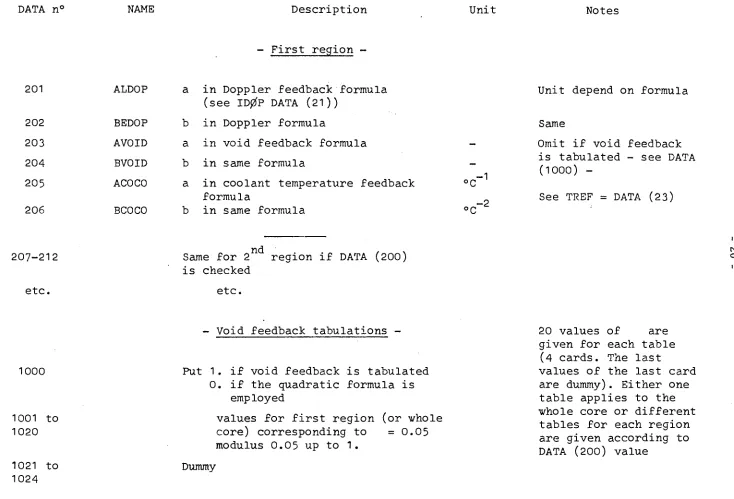
First region
201
ALDO
Ρ
202
203
204
205
BEDOP
AVOID
BVOID
ACOCO
b
a
b
a
206
BCOCO
in Doppler feedback formula
(see IDØP DATA (21))
in Doppler formula
in void feedback formula
in same formula
in coolant temperature feedback
formula
in same formula
1
2
Unit depend on formula
Same
Omit if void feedback
is tabulated see DATA
(1000)
See TREF = DATA (23)
207212
etc.
Same for 2
is checked
etc.
nd
region if DATA (200)
O [SJ1000
1001 to
1020
1021 to
1024
Void feedback tabulations
Put 1. if void feedback is tabulated
0. if the quadratic formula is
employed
values for first region (or whole
core) corresponding to
= 0 . 0 5
modulus 0.05 up to 1.
Dummy
20 values of
are
given for each table
(4 cards. The last
[image:24.842.61.795.61.560.2]DATA n°
NAME
Description
Unit
Notes
1025 to
1048
etc.
Same for second region if DATA (200)
is checked
etc.
281
282
283
284
285
286
287
288
289
290
291
292
D1R1
SA1R1
SSDR1
D2R1
SAR1
D1R2
Reflector constants
-D -Diffusion coefficient - fast
group - first reflector
2o.
AAbsorption cross section
-fast group - idem
Σ
%4
Slowing down cross section
-idem
D Diffusion coefficient
-Thermal group - idem
Σο.
ζAbsorption cross section
-Thermal group - idem
Dummy
D.
1
si
Same for 2 reflector
cm
cm
-1
cm
-1
cm
cm
-1
First reflector
corresponds to
inlet of coolant.
Second to outlet.
ts)
DATA n°
NAME
Description
Unit
Notes
- Initial Data for restarted problem
Only f o r IDST = 0
301-400
401-500
1401-1500
1501-1600
CI(I)
CXE(I)
P1(I)
P2(I)
Iodine concentrations in core mesh points atoms/cm"
Xenon concentrations in core mesh points atom/cm
Fast fluxes in reactor mesh points
Thermal fluxes in reactor mesh points
neut/sec cm
r
neut/sec cm
The first values are
always zero. If any
reflector exists
three meshes are
allocated for it
IS)Perturbation values for Iodine and
-Xenon
Only if IXE = -1
501-600
601-700
FRI(I) Fraction that multiplies equilibrium
values of Iodine concentration in each
core point
DATA n °
NAME
Description
Unit
Notes
Power Tabulation
-701-750
751-800
SI
Times for Power tabulation
Corresponding Power values
The code will interpolate linearly
among values given. If two
successive 0. values for power are
given, the code will calculate a
shut down period in a single step
and restart at the next value of
time and power
hours
watt
The first time must be 0.
Giving two times the same
value in succession, a
step in power is introduced
After the last time given
the power is kept constant.
- Cooling channel specifications -
Only if CHANN > 0
2901
2902
2903
NF Number of radial meshes in the fuel
rod
ύ
10.
ISTD 1. Standard formulae for water are
selected
0. Heat transfer constants given in
input
ITIPØ 0. or blank Cylindrical fuel rods
1. Slab fuel element
-1. General geometry
DATA n°
NAME
Description
Unit
Notes
2904
2905
2906
IVAR
0. Thermal conductivity in fuel
elements are constant
1. Variable conductivity (exponential
formula)
2. Variable conductivity (quadratic
formula)
JPjzfW
0. Constant power density along the
thickness of the fuel rod
1. Power shape in radial zones given
in input
ITET
0. Ôcalculated by the code
1. θ given in input
See DATA (3021)to(3023)
Channel data
Only if CHANN> 0
+ See DATA (20)
3001
3002
3003
3004
3005
A
DIAF
GAPTH
CLTH
AKF
3006
RGAP
Coolant cross section area (referred
cm
dto a single rod)
Diameter of the fuel rod (or thickness
cm
of the slab)
Thickness of the gap
Thickness of the cladding
Thermal conductivity of the fuel
(at reference temperature if
variable)
Thermal resistance of the gap
cm
cm
watt/cm°C
2
cm °C/watt
DATA n°
3007
3008
3009
NAME
AKCL
FLØW
FMDFØ
3010
Τ
SAT
3011
3012
3013
3014
R0
ROVAP
CP
HLAT
Description
Thermal conductivity of the cladding
(at ref.temp.)
Coolant total mass flow into core
in initial conditions
Feedwater mass flow in initial
condition
(During transient it will be
taken proportional to power)
Saturation temperature of the
coolant
Liquid coolant density
Vapour density
Liquid coolant specific heat
Latent heat of vaporization
Unit
watt/cm°C
m.ton/hour
m.ton/hour
Notes
Kelvin
gr/cm
/
3gr/cm
Joule/gr°C
Joule/gr
Used to evaluate inlet
enthalpy of coolant
(see later)
tSJ
αϊ
- Heat transfer parameters -
Only i f ISTD = 0.
3015
3016
3017
3018
HC Convective heat transfer coefficient
(omit if standard)
HB Boiling heat transfer parameter
φ
= HB AT" (idem)
AN Exponent in the boiling heat
transfer correlation (idem)
TAU Bowring ratio of heat transmitted
through vapour bubbles to total
heat transmitted by boiling mechanism
watt/cm °C Omit if standard
watt/cm °C Omit if standard
DATA n°
NAME
Description
Unit
Notes
3019
3020
AK
ZE
Benkoff's K slip constant (
S = ¿
Relaxation parameter for void profile in
diabatic two phase flow
cm
Omit if standard
Omit lacking
information
3021
3022
3023
TKF
AKF1
AKF2
Variable conductivity in fuel
To
in formula K = AKF + a exp [(TTo)/bJ
or formula K =
A K F C +a (TTo)+b(TTo)
£3024
3025
3026
TKCL
AKCL1
AKCL2
To
a
b
for fuel conductivity
in same formulae for cladding
conductivity
Parameters for special geometries
Kelvin
If To is omitted
.n
watt/cm°C
one of the formulae,
or °C~^
°C or °C2
t h e v a l u e i s k e p tconstant to AKF =
DATA (3005)
The formula chosen
same
j
j
.,,,.
depends on IVAR =
DATA (2904)
(V
3027
3028
3029
SWID
Slab width (only for slab elements ITIP0=1)
cm
TINPUT Value of θ parameter (only if ITET=1.)
°C
ELSUR Area of the heating surface per cm of height
cm
For slab geometry
DATA
3030
3031
to
3040
3041
to
3050
n°
NAME
ACONCL
CONF(I)
FMASS(I)
Description
Thermal conductance of cladding per cm
of height
Thermal conductance from one zone to the
following in the outer direction (per
cm of height)
Mass/cm in every zone in the fuel
(Center to periphery)
Unit
watt/cm°C
watt/cm°C
gr/cm
Notes
ITIPO = 1
idem
idem
30 51
3052
3053
3054
PRESS
vise
WCØN
D
IAH
Data for standard water formula
Average pressure
Liquid water viscosity
Liquid water heat conductivity
Hydraulic diameter of the coolant
channel
Only if ISTD=1
Kg/cm
poise
watt/cm°C
cm
- j
3055
3056
3057
HENO
Inlet enthalpy parameters
Η λ In formula for feed water enthalpy
ƒ subcooling
a [ HFDW = Ho + a Ρ + b Ρ
2b J where Ρ is Power in MW
Joule/gr
Joule/gr MW
Joule gr MW
£The inlet subcooling
of the coolant is
calculated as:
H. = U » HFDW +
in
DATA n° NAME Description
3058 XDR Carry under ratio, i.e. quality of coolant
in downcorner at the mixing point with feed
water
Unit Notes
where U is the ratio
FMDF . . _ .
FTØW"
between feed
-water flow and total
flow
1851
1852
1853
KTP
U P
I 2 P
1854
1855
1856
1857-1862
etc
IDST
Printing and calculation specifications
-Number of time steps for the first printing
pattern
Number of time steps for restricted print
(Only average values)
Number of time steps for extended print
(Complete map of fluxes, concentrations,
voids etc)
if checked 1 gives special print of
convergence
steps - generally left blank
Dummy
.nd
Same for 2 printing pattern
Any number of successive
printing patterns may
be given. The problem
will stop when the last
is completed.
A new problem is then
started unless the title
card of the problem has
1 in column 6, in which
case the run is stopped.
00
1
3 0 .
î .
8 0 0 .
0. 0004
1 .
5 .
1 5 .
2 . 2
0 . 4
2 . 2
0 . 4
0 . 0 0 6
2 . 3
2 . 3
3 .
1 . 8
0 . 1 6
5 . 1 6
7 3 .
- 1
2 0 .
SAMPLE PROBLEM
1
2 .
0 . 0 6 3 5
+ 0 6 3 0 0 .
1 3 0 0 0 .
0 . 0 0 5
1 .
43
6 1
1 5 .
81
0 . 0 1 5
0 . 0 6 1
0 . 0 1 5
0 . 0 6 1
201
0 . 1 7 5
281
0 . 0 0 0 5
0 . 0 0 0 5
2901
1 .
3001 1.25
1 4 0 0 0 .
1 5 0 0 .
3051
0 . 0 0 0 1
1851
2 .
3 6
1 8 0 0 .
0 . 0 0 4
6 0 0 0 0 .
0 . 0 0 0 4
1 .
43
6 2
1 0 4
0 . 0 3 7
0 . 0 8 7
0 . 0 3 7
0 . 0 8 7
204 0 . 0 9
292
0 . 0 7 5
0 . 0 7 5
2902
3014
0 . 0 0 1
1 0 0 0 .
3056
0 . 0 0 5 6
1856
4 .
FOR XBWR
3 0 .
0 . 2 8 7
4 0 .
5 6 0 .
0 . 0 0 5
- 2 .
0 . 0 0 5
0 . 0 3 5
0 . 0 0 5
0 . 0 3 5
- 0 . 1
0 . 2 9
0 . 2 9
0 . 0 9
5 6 0 .
1 . 2 5
1 .
- 0 4 0 . 2 1 1
4 0 .
5 6 0 .
- 0 . 1 5
1 0 0 .
0 . 0 0 2 3
0 . 0 0 2 3
0 . 0 1
0 . 0 1
0 . 0 2 3
0 . 7 4
- 1 1 5 0 .
0 . 3 2
- 0 4 0 . 2
1 0 0 .
- 0 . 4 2
1 . 5
0 . 0 3 6 6
- 1 0
- 1 7
Η
i
fed
O W CO
1
APPENDIX C
SAMPLE OUTPUT
-COSTANZA AXIAL XFNON-BOILING CHANNEL
T . C . R . FURATOM-ISPRA
1 7 13 19 25
U
6 1 8 1 87 93 99 2 0 1 2 8 1 2B7 2 9 0 1 3 0 0 1 3007 3013 3 0 5 ] 18510 . 3 0 0 0 0 O E 0 . 1 0 0 0 0 0 E 0. 800000E 0 . 0
0 . 4 0 0 0 0 0 E -0 . 1 -0 -0 -0 -0 -0 E 0 . 5 0 0 0 0 0 E 0 . 1 5 0 0 0 0 E 0 . 2 2 0 0 0 0 E 0 . 4 0 0 0 0 0 E 0 . 2 2 0 0 0 0 E 0 . 4 0 0 0 0 O E 0 . 6 0 0 0 0 0 E -0. 230000E 0 . 2 3 0 0 0 0 E 0 . 3 0 0 0 0 0 E 0. 180000E 0 . 160000E 0 . 5 1 6 0 0 0 E 0 . 7 3 0 0 0 0 E 0 . 2 0 0 0 0 0 E
02 O l 09
- 0 3 O l O l 0 2 O l 0 0 O l 0 0 -02 O l Ol O l Ol 0 0 O l 0 2 02 2 8 14 2 0 2 6 3 2 6 2 8 2 88 9 4 100 2 0 2 2 8 2 2 8 8 2 9 0 2 3 0 0 2 3 0 0 8 3 0 1 4 3 0 5 2 1 8 5 2
0 . 2 0 0 0 0 0 E O l 0 . 6 3 5 0 0 0 E - 0 1 0 . 3 0 0 0 0 O E 03 0 . 1 3 0 0 0 0 E 05 0.5OOOOOE-02 0 . 1 0 0 0 0 0 E O l
0 . 1 5 0 0 0 0 E 0 2 0 . 1 5 0 0 Γ 0 Ε - 0 1
0 . 6 1 0 0 0 0 F - 0 1 0 . 1 5 0 0 0 O F - 0 1 0 . 6 1 0 0 0 0 E - 0 1 - 0 . 1 7 5 0 0 0 E 0 0
0 . 5 0 0 0 0 0 E - 0 3 0 . 5 0 0 0 0 0 E - 0 3 0 . 1 0 0 0 0 0 E O l 0 . 1 2 5 0 0 0 E O l 0 . 1 4 0 0 0 OF 05 0 . 1 5 0 0 0 0 E 0 4 0 . 1 0 0 0 0 OE-03 0 . 2 0 0 0 0 0 E Ol
SAMPLE PROBLEM 3 9 15 2 1 27 33 83 P9 Q *
1 0 Ì 203 283 2 8 9
3 0 0 3 3 0 0 9
3 0 5 3 1 8 5 3
0 . 1 8 0 0 0 0 E 04 0 . « 0 0 0 0 0 E - 0 2 0 . 6 0 0 0 0 0 F 05 0 . 0
0 . 4 0 0 0 0 0 F - 0 3 0 . 1 0 0 0 0 0 E O l
0 . 3 7 0 0 0 0 E - 0 1 0 . 8 7 0 0 0 0 E - 0 1 0 . 3 7 0 0 0 0 E - 0 1 0 . 8 7 0 0 0 0 E - 0 1 - 0 . 9 0 0 0 0 0 F - 0 1 0 . 7 5 0 0 0 0 E - 0 1 0 . 7 5 0 0 0 0 F - 0 1
0 . 1 0 0 0 0 0 F - 0 2 0 . 1 0 0 0 0 0 E 0 *
0. 5 6 0 0 0 0 E - 0 2 0 . 4 0 0 0 0 0 F O l
FOR XBWR 4 10 16 22 28 34 84 9 0 96 1 0 2 204 2 8 * 290
3 0 0 « 3 0 1 0
3 0 5 4 1 8 5 4
0 . 3 0 0 0 0 0 E 0 2 0 . 2 8 7 0 0 0 E - 0 4 0 . 4 0 0 0 0 0 F 0 2 0 . 5 6 0 0 0 0 E 0 3 0 . 5 0 0 0 0 0 F - 0 2 - 0 . 2 0 0 0 0 0 E O l
0 . 5 O O 0 0 0 E - 0 2 0 . 3 5 0 0 0 0 E - 0 1 0 . 5 0 0 0 0 0 E - 0 2 0 . 3 5 0 0 0 0 E - 0 1 - 0 . 1 0 0 0 0 0 E 0 0 0 . 2 9 0 0 0 0 E 0 0 0 . 2 9 0 0 0 0 F 0 0
0 . 9 0 0 0 0 0 E - 0 1 0 . 5 6 0 0 0 0 E 03
0 . 1 2 5 0 0 0 E O l 0 . 0
*
l ì
17 23 29 35 85 9 1 9 7 103 285 2 9 13 0 0 5 3 0 1 1
3055 1855
O.IOOOOOE 0 . 2 1 1 0 0 0 F -0 . 4 -0 -0 -0 -0 -0 F 0 . 5 6 0 0 0 0 E - 0 . 1 5 0 0 0 0 F O.IOOOOOE
0 . 2 3 0 0 0 0 E -0 . -0
0 . 2 3 0 0 0 0 E -0 . -0
0 . 1 0 0 0 0 0 E 0 . 1 0 0 0 0 0 E
0 . 2 3 0 0 0 0 E -0.74-00OOF
- 0 . 1 1 5 0 0 0 E 0 . 0
O l - 0 *
0 2 03 0 0 0 3
- 0 2
- 0 2
- O l - O l
- O l 0 0 0 4 6 12 18 2 4 3 0 36 86 9 2 9 8 1 0 4
2 8 6 2 9 2
3 0 0 6 3 0 1 2
3 0 5 6 1 8 5 6
0 . 3 2 0 0 0 0 E - 1 0 0 . 2 0 0 0 0 0 E -0 . -0
O.IOOOOOE - Ο . Λ 2 0 0 0 0 Ε
0 . 0
0 . 0 0 . 0 0 . 0 0 . 0
0 . 0 0 . 0
0 . 1 5 0 0 0 0 E -17
0 3 0 0
O l 0 . 3 6 6 0 0 0 E - O Î
0 . 0 0 . 0
FUEL RADIUS
0.62500E 00
CLAD RADIUS
0.62600F 00
FUEL DATA
EXT.RADIUS
0.71600E 00
3REGI0NS IN FUEL
RADII
0.36084 0.51031 0.62500
RELATIVE POWER
0.33333 0.33333 0.33333
TEMPERATURE INDEPENDENT CONSTANTS
0.230000E-01
TOTAL
FEEDWA1
KCL
0.16CO00F 00
3H^P·14000E_05T0N/HQUR
FLOW Ò.10000E
/HOUR
FÊEDWATER SUBCOOLING HFDW »-0.11500E 0* + 0 . 0 *POWFR(MW) + 0 . 0
INLET SUBC00LING-U*HFDW+tl.-U)*CARRVUNDER*VAP.HEAT*-0.R2143E 02
HEAT TRANSFER CONSTANTS
HC 0.44958E 01
TETA 3.53
HB 0.25615E-01
TETAF 2.56
AN K4 . 0 0 0
0.858
*P0WER**2 »-0.11500E 04 JOULE/GR
TAU 0.43500
ZE 0 . 0
HOURS 0 . 0 POWER 0.80000E 09 MASSFL 0.10000E Ol ROD INSERTION 0.10000E 03 I N T * * * * * *
AVERAGE VOID FRACTION 0.2807
- - - QUALITY 0.0824
SUBCOOLED BOILING NODE 10
BULK BOILING NODE 16
I
POWER/CM OF CHANNEL I N CORE REGIONS
0.2328E 03 0 . 1775E 03
HOURS
0 . 0
IT
INT * * * * * *
POWER * OéSOOOOE 0 9REP » 0*I3387E 03
2
3
4
5
*
8
9
Î?
12
0.10764D 12
0.I1246D 13
0.98195D 13
0.159100 14
0.21994D 14
0.28307D 14
0.35132D 14
0.42827D 14
0.51850D 14
0.62782D 14
0.76377D 14
0.3
0.13197D
0.12546D
0.11552D
0.10374D
0.9173
ID _
.80396D 14
70129D 14
0.61O28D
0.53027D
0.45983D
i
1!
1!
il
14
0 . 3 9 7 1 8 D
0 . 3 4 045 D
0 . 2 8 7 8 6 D
0 . 2 3 7 7 2 0
(W18856D
0 . 1 3 9 0 8 D
0 . 8 7 9 4 9 D
0 . 1 0 1 1 6 D
0 . 9 7 2 3 2 D
14
14
14
tí
it
14
14
i!
1 1 AVERAGES0 . 6 2 1 1 3 D 14
0 . 5 0 6 9 4 D 14
0 . 6 6 4 8 5 D 14
0 . 7 4 3 2 2 D 14
0 . 7 7 2 8 I D 14
0 . 7 6 4 3 6 D 14
0 . 7 2 7 6 8 D 14
0 . 6 7 1 3 9 D 14
0 . 6 0 4 2 8 D 14
0 . 5 3 5 4 4 D 14
0 . 4 7 0 1 9 D 14
0 . 4 1 0 9 2 D 14
0 . 3 5 8 2 5 D 14
0 . 3 1 1 8 6 D 14
0 . 2 7 0 9 4 D 14
0 . 2 3 4 4 7 D 14
0 . 2 0 1 3 8 D 14
0 . 17061D 1 *
0 . I 4 1 1 9 D 14
0 . 1 1 2 2 6 D 14
0 . 8 3 1 4 4 D 13
0 . 5 5 1 1 0 D 13
0 . 6 8 6 0 7 D 13
0 . 1 2 6 3 0 D 13
0 . 3 5 6 0 1 D 14
0 . 0
0 . 0
0 . 0
0 . 0
0 . 0
0 . 0
0 . 0
0 . 0
0 . 0
0 . 0
0 . 0
0 . 0
0 . 0
0 . 0
8í8
0 . 0
0.0
0 . 0
0 . 0
0 . 0
0 . 0
0 . 0
0 . 0
0 . 0
0 . 0
0 . 0
0 . 0
0 . 0
0. D
CI
15
if
il
0 . 4 5 4 8 E 15
0 . 5 9 7 8 E 15
0 . 7 0 3 7 E
0 . 7 8 5 2 E
0 . 8 5 2 2 E
0 . 9 1 0 2 E
0 . 9 6 2 5 E
O.IDIOE 16
0 . 1 0 5 5 F 16
0 . 1 0 9 6 E 16
0 . 1 1 3 6 F 16
0 . 1 1 5 2 F 16
0 . 1 1 5 7 E 1 6
0 . 1 1 5 6 F 1 6
0 . 1 1 4 9 E 1 6
0 . 1 1 3 6 E 1 6
0 . 1 1 1 9 E 16
0 . 1 0 9 8 E 16
0 . 1 0 7 3 E 16
0 . 1 0 4 5 E 16
0 . I 0 1 5 E 1 6
0 . 9 8 1 3 E 1 5
0 . 9 4 5 0 F 15
0 . 9 0 5 4 E 15
0 . 8 6 1 3 E 15
0 . 8 1 0 8 E 15
0 . 7 5 0 9 E 15
0 . 6 7 6 2 E 15
0 . 5 7 7 9 E 15
0 . 4 4 7 8 E
15
HFL
0 . 7 1 2 6 F
0 . 1 1 1 9 E
0 2
01
0 . 1 5 4 1 E 0 2
0 . 1 9 8 0 E 02 02 02
ο · 1
0 . 2 4 5 3 E
0 . 2 9 8 5 E
0 . 3 6 1 0 E 0 2
0 . 4 3 6 8 F 0 2
0 . 5 3 1 2 E 02
0 . 6 5 3 2 F
0 . 8 5 1 2 F
0 . 9 5 1 2 F
0 . 9 8 8 9 F
0 . 9 7 7 9 E
0 . 9 3 0 9 F
0 . 8 5 8 7 E
0 . 7 7 2 7 E
0 . 6 8 4 5 F
0 . 6 0 1 0 F
0 . 5 2 5 1 F 02
0 . 4 5 7 7 F 02
0 . 3 9 8 4 E 02
0 . 3 4 6 0 E 0 2
0 . 2 9 9 4 E 02
0 . 2 5 7 i l 02
0 . 2 1 7 8 F 0 2
0 . 1 8 0 2 F 0 2
0 . 1 4 3 2 F 0 2
0 . 1 0 6 0 F 0 2
0 . 6 9 9 6 F 0 1
02
02
02
02
02
02
02
02
02
02
DK
0.1444F02
0.2428F02
0.3424E02
0.4429E02
0.5485F02
0.6642E02
0.7957E02
0.9498E02
0.1135F01
0.1597F01
0.24
94F01
0.3314F01
0.4047F01
0.4665F01
0.5158F01
0.5791F01
0.6537E01
0.7088E01
0.7483E01
0.7769F01
0.7978E01
0.8131F01
0.8242F01
0.8321F01
0.8372F01
0.8399F01
0.8401F01
0. 8376E01
0.8327F01
0.8258E01
VF
0 . 0
0 . 0
0 . 0
0 . 0
0 . 0
0 . 0
0 . 0
0 . 0
0 . 0
0 . 4 6 8 6 F 0 1
0 . 1 0 1 1 F 0 0
0 . 1 5 4 1 F
0 . 2 0 2 2 F
0 . 2 4 4 1 F
0 . 2 7 9 6 E
0 . 3 4 1 5 F
0 . 3 8 9 1 E
00 00 0 0 0 0 0 0 0 0
0 . 4 2 4 9 F 0 0
0.4525F
0.4742F
0.4914F
0.5053
F
0 0 0 0 0 0 00 0 . 5 1 6 6 E 0 0 0 0 0 0
0 . 5 259F
0 . 5 3 3 6 E
0 . 5 3 9 8 F 0 0
0 . 5 4 4 8 F 0 0
0 . 5 4 8 7 F
0 . 5 5 1 5 F
0 . 5 5 3 3 F
0 0 0 0 0 0
TS
0 . 5 4 5 9 F 0 3
0 . 5 4 7 1 F 0 3
0 . 5 4 8 5 E 03
0 . 5 5 0 0 F 0 3
0 . 5 5 1 8 E 0 3
0 . 5 5 39F 0 3
0 . 5 5 6 3 F 0 3
0 . 5 5 9 3 F 0 3
0 . 5 6 2 9 F 0 3
0 . 5 6 7 1 F 0 3
0 . 5 6 7 6 F 03
0 . 5 6 7 8 F 0 3
0 . 5 6 7 9 F 0 3
0 . 5 6 7 9 F 0 3
0 . 5 6 7 8 E 0 3
0 . 5 6 7 6 F 03
0 . 5 6 7 4 F 03
0 . 5 6 7 2 F 0 3
0 . 5 6 7 0 F 0 3
0 . 5 6 6 7 F 03
0 . 5 6 6 5 F 0 3
0 . 5 6 6 3 F 0 3
0 . 5 6 6 1 F 0 3
0 . 5 6 5 8 E 0 3
0 . 5 6 5 5 F 0 3
0 . 5 6 5 1 E 0 3
0 . 5 6 4 5 F 03
0 . 5 6 3 1 F 0 3
0 . 5 6 2 4 F 0 3
0 . 5 6 1 6 F 03
TIC
0 . 5 5 02F
0 . 5 5 3 8 E
0 . 5 5 7 7 F
0 . F 6 1 9 F 0 3
0 . 5 6 6 5 F 0 3
0 . 5 7 1 8 F 0 3
0 . 5 7 8 0 F 0 3
0 . 5 8 5 5 F 0 3
0 . 5 9 4 8 F 0 3
0 . 6 0 6 3 F 0 3
0 . 6 1 8 7 F 0 3
0 . 6 2 4 9 E 0 3
0 . 6 2 7 2 F 0 3
0 . 6 2 6 6 F 0 3
0 . 6 2 3 6 F 0 3
0 . 6 1 9 1 F 0 3
0 . 6 1 3 8 F 0 3
0 . 6 0 8 3 F 0 3
0 . 6 0 3 0 F 0 3
0 . 5 9 8 2 E 0 3
0 . 5 9 4 0 F 03
0 . 5 9 0 2 E 0 3
0 . 5 8 6 8 F 0 3
0 . 5 8 3 7 F 0 3
0 . 5 8 0 9 F
0 . 5 7 8 2 E
0 . 5 7 5 3 F
0 . 5 7 1 7 F
_
0 . 5 6 8 7 F 0 3
0 . 5 6 5 8 F 0 3
03 03 03 03 03 03 0 3
TL
0 . 5 4 4 3 F 0 3
0 . 5 4 4 6 F
0 . 5 4 5 1 E
0 . 5 4 5 6 F
0 . 5 4 6 4 F
0 . 5 4 7 2 F 0 3
0 . 5 * 8 3 F 0 3
0 . 5 4 96F
0 . * 5 1 1 F
0 . 5 « 1 1 F
0 . 5 5 2 2 F 0 3
0 . «5535F 0 3
0 . 5 5 5 1 F
0 . 5 5 6 7 F
0 . 5 5 8 3 F 0 3
0 . 5 6 0 0 F 0 3
0 . 5 6 0 0 F 0 3
0 . 5 6 0 0 F 0 3
0 . « 6 0 0 F 0 3
0 . 5600F 0 3
0 . 5 6 0 0 F 0 3
0 . « 6 0 0 F 0 3
0.56OOF 0 3
0 . 5 6 0 0 F 0 3
0.«>600F 0 3
0 . 5 6 0 0 F 0 3
0 . 5 6 00F 0 3
0 . 5 6 0 0 E 0 3
0 . 5 6 0 0 F 0 3
0 . 5 6 0 0 F 0 3
03
03
03
03
03
03
03
03
03
TFMAX
0 . 6 7 4 3 F 0 3
0 . 7 4 8 8 F 0 3
0 . 8 2 6 3 F 0 3
0 . 9 0 6 8 E 0 3
0 . 9 9 3 8 F 0 3
0 . 1 0 9 2 F 04
0 . 1 2 0 7 F 04
0 . I 3 4 6 F 0 4
0 . 1 5 2 0 F 0 4
0 . 1 7 4 4 F 04
0 . 2 1 0 2 F 04
0 . 2 2 8 2 F 04
0 . 2 3 5 0 F 04
0 . 2 3 3 0 F 04
0 . 2 2 4 5 E 04
0 . 2 1 1 5 F 04
0 . 1 9 6 0 F 04
0 . 1 8 0 I F 04
O . I 6 5 0 F 0 4
0 . 1 5 1 3 F 04
0 . 1 3 9 1 F 0 4
0 . 1 2 8 4 F 04
0 . 1 1 9 0 F 04
0 . 1 1 0 5 F 04
0 . 1 0 2 9 F 0 4
0 . 9 5 7 5 E 03
0 . 8 8 9 2 F 0 3
0 . 8 2 1 2 E 0 3
0 . 7 5 3 4 E 0 3
0 . 6 8 7 6 E 0 3
INITIAL CRITICALITY
SEARCH
SPRG » 0.10000E-01 DAPF
0 . 1 0 0 0 0 E - 0 1
LF =
50
ITERN SPCR
1 0 . 0
2 - 0 . 1 0 0 0 E - 0 1
3 -0.4999E-02
4 -0.3985E-02
5 -0.3790E-02
6 -O.3624E-02
7 -0.3688E-02
8 - 0 . 3 6 5 4 E - 0 2
9 - 0 . 3 6 0 6 E - 0 2
10 - 0 . 3 6 2 1 E - 0 2
11 - 0 . 3 6 1 7 E - 0 2
12 - 0 . 3 6 1 3 E - 0 2
KEFF 1.003626
DC D