scroll down to view the document itself. Please refer to the repository record for this item and our policy information available from the repository home page for further information.
Author(s):Hosny, Wada; Dobrucky, B.; Pokorny M.
Title:Virtual two axes strategy for speeding up the determination of the reference current in single phase active power filters.
Year of publication:2009
Citation: Hosny, W., Dobrucky, B., Pokorny M. (2009) ‘Virtual two axes strategy for speeding up the determination of the reference current in single phase active power filters.’ Proceedings of Advances in Computing and Technology, (AC&T) The School of Computing and Technology 4th Annual Conference, University of East London, pp.112-119
Link to published version:
VIRTUAL TWO AXES STRATEGY FOR SPEEDING UP THE
DETERMINATION OF THE REFERENCE CURRENT IN
SINGLE PHASE ACTIVE POWER FILTERS
W Hosny
1, B Dobrucky
2, M Pokorny
3 1University of East London, Scot, 46 University Way, Docklands E16 2RD, email: [email protected]
2
Department of Mechatronics and Electronics 3 Department of Electrical Power Systems,
University of Zilina, 8215/ 1 Univerztina Street, Zilina, SK01026, Slovak Republic
[email protected], [email protected]
Abstract: Virtual two axes or orthogonal transformation technique instigated by Akagi in 1984 for the investigation of the novel terminology of instantaneous power in three phase power systems and extended by Dobrucky and Pokorny in 1999 for the determination of the instantaneous power in single phase power systems, is utilised in this paper for the fast evaluation of the harmonic distortion and reactive compensating currents in single phase shunt active power filters. Expressions for these currents under different compensating conditions are derived in this paper. Control strategies are utilised to implement these expressions. This results in providing excellent transient response of the filter which is demonstrated experimentally. This fast dynamic response is achieved via the rapid evaluation of the compensating current using a digital signal processor when the two axes strategy is used.
1. Introduction:
In this section orthogonal transformation technique (virtual two axes strategy) instigated by Akagi et al, (Akagi Kanazawa and Nabae, 1983) and applied to a single phase power system is briefly explained. This technique was described in detail in two of the authors’ previous publication, (Hosny and Dobrucky, 2008). By adopting this technique expressions for the reference currents used in an active power filter for the compensation of harmonic distortion and reactive power are derived. Consider a single phase power system feeding a non linear load in the form of a solid state diode bridge rectifier with an inductive load connected to the dc side. Adopting the virtual two axes strategy, the real and the virtual components of the supply voltage and current can be represented in vector
Fig1. Trajectory of voltage and current
Fig.2 shows the arrangement of the real and virtual circuits of the complex single phase power system under investigation. As it is shown in this figure, the real and virtual circuits should be synchronised by the so called “SYNC” signal. This implies that both of the real and virtual components are initially equal to zero.
Fig.2 Real and virtual circuits of the complex power system under investigation
2. Instantaneous Reactive Power:
In this section the use of the pqr instantaneous reactive power method, described in references (Dobrucky, 1985), (Kim and Akagi, 1999) and (Akagi, Kanazawa and Nabee, 1984), for
compensation of the reactive power and harmonic filtering is explained.
The instantaneous active and reactive power equations for the complex power system under consideration are given in the αβ domain, as described in references (Akagi, Kanazawa and Nabae, 1983),(Kim and Akagi, 1999) and ( Akagi, Kanazawa and Nabae, 1984), as follows:
p = vαiα + vβiβ
(1) q = vαiβ vβiα
Fig.3 depicts the time variation of p and q for the complex single phase power system under consideration. In this figure PAV and
QAV respectively are the average values of
the active and reactive power.
Fig.3 Instantaneous and average values for p and q for a complex single phase, the real component of which consists of a cosinusoidal voltage supply feeding a solid state rectifier bridge
The instantaneous power factor, Ф, is defined as:
Ф = tan 1 (q/p) (2)
It is important to point out that the values of p, q and Ф in Eqs (1) and (2) are
Fig.4 Voltage in a complex single phase power system represented in fixed and rotating frames
of reference
The pqr theory is introduced in references (Kim and Akagi, 1999) and (Kim, Blaabjerg, BakJensen and Choi, 2001), where the current, voltage and power equations are projected in pqr rotating frame of reference. Fig.4 shows the voltage components in both of the fixed αβ and rotating pq frame of reference for a single phase power system. The raxis is considered to be the zero axis.
In Fig.4, vαβ is defined as:
vαβ =
2 2
b a v
v + (3)
Angle, θ is defined as:
Θ = tan 1 ( vα/vβ) (4)
3. Derivation of Reference Current
Expressions for the Active Filter:
In this section instantaneous expressions for the reference currents for an active power filter to compensate for the harmonic distortion and reactive power in the single phase power system under investigation are derived.
Because of the symmetry of the complex voltage and current vectors trajectories, Fig.1, the average value of the active and
reactive powers for both of the real and virtual phases can be evaluated from Eq.1 as follows:
P RE AV = PAV/2 = 2/T v i v i dt
T
) (
4 /
0
b b a a +
ò
(5)
Q RE AV = QAV/2 = 2/T v i v i dt
T
) (
4 /
0
a b b a -
ò
The real phase current, iα, can be derived
from Eqs.1 and 3 as follows:
iα = 1/vαβ 2 ( vα p vβ q)
= 1/vαβ ( vα (PAV + p~) vβ (QAV + q~) ) (6)
In Eq.6, p~ and q~ respectively are the ripple
active and reactive power components, PAV
and QAV respectively are the average active
and reactive power of the complex power system under consideration.
Reference current for the active filter of the single phase system under consideration can assume different expressions depending on the special requirements of compensating for the reactive power or filtering the distortion harmonics. Three special cases are listed below:
i) Reference current for distortion harmonic filtering and reactive power compensation
iref = 1/vαβ 2 (vα p~ vβ q)
= 1/vαβ 2 (vα (pPAV) vβ (qqAV)) (7)
ii) Reference current for average reactive power compensation
iii) Reference current harmonic distortion compensation
iref = 1/vαβ 2 (vα p~ vβ q~ ) (9)
4. Experimental Results:
A test rig was set up to verify the theoretical derivations above. An active power filter is implemented with the current reference of Eq.(6) used as an input to the filter and the digital signal processing of the voltages and currents is implemented using a 32 bit floating point DSP,TMS320C31. The configuration of the experimental setting is shown in Fig.5. The single phase power system under experimentation is a co sinusoidal supply voltage feeding a diode bridge rectifier with an RL load connected to the dc side. The active power filter is a shunt type comprising of a fullycontrolled ac to dc IGBT bridge rectifier together with a passive filter in the form of an input inductor L of 1.2 mH and a capacitor of 10,000 μF connected to the output. Both the load and the active power filter are rated at 25 kVA. The output current of the active power filter is controlled by a hysteresis comparator to confine the switching frequency to 15 kHz.
4.1 Steadystate operation:
Fig.6 shows the waveforms of the load current, the compensating current of the active power filter and the supply current. The active power filter performed its task of compensating for the harmonic distortion as the supply current is converted to a pseudo sinusoidal waveform.
Fig.5 Block Diagram of the Experimental Setting
Fig.6 Supply current to the single phase power system under consideration before (top) and after (bottom) the implementation of the active
power filter
The top waveform in Fig.6 shows the original supply current waveform and the bottom waveform shows the supply current wave form after the implementation of the active power filter. The middle wave form is the compensating current of the active power filter.
4.2 Dynamic Operation:
Fig.7 Schematic diagram showing the evaluation procedure of the active power filter compensating current
reference for the active power filter and the cycle time of the digital signal processor implemented in order to execute these computations. In addition, the values of the reactive components within the active power filter circuitry will yield an impact on its dynamic operation. Fig.7 shows the block diagram for the computation of the reference current for the active power filter. This block diagram is valid for the various methods of reference current computations using the reference current expressions referred to earlier.
In Fig.7: Vdc is the voltage across the
filtering capacitor of the rectifier circuit. Vdc ref is the reference capacitor voltage. This
was set at 900 V. The peak value of the supply voltage, which yields the supply current is, is equal to 300 V. The supply
frequency is equal to 50 Hz. The supply input resistance Rs and inductance,Ls
respectively are 0.2 Ω and 1 mH. These are not shown in Fig.7. Icharg is the filtering
capacitor dc charging current which is multiplied by cos(ωt) in order to yield the ac charging current. The cosinusoidal time varying function is derived via a phase
locked loop circuit connected to the supply. The load current iload is supplied to the
inductive load constituting of a resistance,Rload, and an inductance Lload,
respectively of 1Ω and 6 mH in values. The shunt filter current ifilter which is equal to
the supply current is minus the load current
iload is the current passing through the active
power filter inductance Lf which has a value
of 1.2 mH. Fig.7 also shows the filtering capacitor voltage regulaor Rv and the active
power filter current regulator RI as PI
controllers. Computations of the load current higher harmonics and reactive components, according to one of the expressions referred to earlier in
Eqs 69, are carried out within the two brackets shown in Fig.7 termed ”Calculations”. These are then subtracted from the load current iload in order to give
the fundamental and unity power factor current, Im1s cos(ωt). As it is shown in Fig.7,
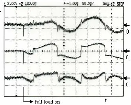
The transient response of the voltage across the filtering capacitor when the load is applied is shown in Fig. 8.
As it can be seen in Fig.8, the capacitor voltage dips to about 600 V upon the load application but the voltage controller,Rv,
responds quickly and brings it back to the reference value of 900 V. The voltage axis in Fig.8 is scaled down by a factor of 100. As it will be illustrated later, the capacitor voltage transients yield a minimum impact on the settling time of the source current. This is because the load power loss component is much lower than the average load power. Fig.9 shows the transient waveforms of the supply current, the load current and the compensating or reference current of the active power. This figure demonstrates the superior dynamic properties of the active power filter under consideration, using the current reference expressions referred to earlier. This is because when the full nonharmonic load is switchedon, the current waveforms, shown in Fig.9, indicate an instantaneous response of the active power filter. In effect, the active power filter responds to the load application immediately after the first time step required by the digital signal processor for the computation of the filter reference current. As computation time advances, the full load power is supplied by the voltage filtering capacitor.
Also, in Fig.9 the supply current response illustrates a time lag, starting from the moment of the full load application. This time lag is caused by the filter inductance,Lf.
The algorithms for the single phase active power filter reference current computations reported in this paper are valid for both harmonics and reactive load current compensation with an extremely fast transient response. This is realised by performing the filter reference current computation implementing the digital signal processor in a time period of one quarter of the periodic time of the supply voltage. This was referred to in Eq.5, where, due to the symmetry of the complex voltage and current trajectories in the Gaussian domain within the proposed two virtual axis strategy, then the integrals required to evaluate the average active and reactive power values could be executed in only a quarter of the periodic time of the supply voltage.
[image:7.595.74.290.175.293.2]The sampling period of the voltages and currents needed to evaluate the active power
Fig. 8 Capacitor Voltage of the Active Power Filter During the Load Application
Fig. 9 Transient Waveforms of the supply current to the single phase power system under
[image:7.595.308.530.181.359.2]filter reference current should be selected to be as small as possible to ensure the smallest possible error introduced in evaluation of the filter reference current. If Euler’s integration routine is used, the integration time step,Dt, required to evaluate the integrals referred to above, could be selected to be equal to the sampling period. Shannon’s theorem states that the sampling frequency should be at least equal to twice the highest frequency of the harmonic load current which is to be filtered out. This implies that the sampling period or the integral time step,Dt, should be much smaller then half the periodic time of the highest harmonic component of the load current. If the sampling period is selected to be equal to one tenth of the periodic time of this highest harmonic component, then in order to compensate for the fifth load current harmonic, Dt should be selected to be equal to 400 μs.
The active power filter theory for single phase power systems using orthogonal αβ transforms or the pqr method with virtually created fictitious phase has been previously reported by some of the present paper authors, (Dobrucky, Pokorny, Racek and Havrila, 1999) and (Dobrucky, Kim, Racek, Roch and Pokorny, 2002). However, in the present work the fast dynamic response of the filter has been demonstrated.
Other authors publications, (Hague, 2002), (Saitou, Matsui and Shimizu, 2003), (Ghartermani, Mokhtari and Iranvani, 2004) and Kunjumuhammed and Mishra, 2005) have targeted single phase active power filters using different techniques to the one presented in this paper but the active power filter reference current evaluation time was reported to be as long as one periodic time of the supply voltage in contrast to a quarter of the periodic time reported in this paper. Listed below are the attributes of the research work reported in this paper:
· The supply voltage of the single phase system supplying a nonlinear load, embodying the active power filter, almost immediately supplies a harmonic current upon the load being switched on. This is realised by the synchronous operation of the active power filter which is made possible by control of the starting up algorithms.
· Due to the rapid dynamic response of the active power filter, fast compensation of any overvoltages during rapid load changes (in particular during sharp load switching off) is feasible.
· The rapid dynamic response of the active power filter could be attributed, in addition to the starting up algorithms, to the fact that the voltage across the filtering capacitor is controlled to be maintained at about three times the maximum value of the supply voltage.
5. Conclusions:
6. References:
Akagi H., Kanazawa Y., Nabae A., “Generalized Theory of the Instantaneous Reactive Power in Three Phase Circuits”, Proceedings IPEC83 Conference, Tokyo (J8), Sept. 1983, pp 13751386.
Akagi H., Kanazaw Y., Nabae A., “Instantaneous reactive Power Compensators Comprising Switching Devices without Energy Storage Components”, IEEE Transactions on AI, vol.20, 1984, No.3, pp 625630.
Dobrucky B, “Analysis and Modelling of Power Semiconductor in Steady and Transient States”, PhD Thesis, University of Zilina, Slovak Republic, 1985.
Dobrucky B. Pokorny M,, Racek V., Havrila R. “A New Method of the Instantaneous Reactive Power Determination for SinglePhase Power Electronic Systems”, Proc. of EPE‘99 Conf., Lausanne (CH), Sept. 1999, pp. CDROM.
Dobrucky B.., Kim H., Racek V., Roch M.,. Pokorny,M. ”Single phase power active filter and compensator using instantaneous reactive power method”, Proc. of PCC’02 Conf., Osaka (JP), Apr. 2002, pp. 167171.
Ghartemani M.K., Mokhtari H., Iravani, M.R., “A Signal Processing System for Extraction of Harmonics and Reactive Current of SinglePhase Systems”, IEEE
Trans. on Power Delivery, Vol. 19, July 2004, pp. 979986.
Haque M.T., “Single phase PQ theory for active filters”, Proc. of IEEE TENCON ’02 Conf., 2002, pp. 19411944.
Hosny W., Dobrucky B., “Harmonic Distortion and Reactive Power Compensation in Single Phase Systems using Orthogonal Transformation Strategy”, WASEAS Transactions on Power Systems, issue 4, volume 3, April 2008.
Kim H., Blaabjerg, F., BakJensen, B., Choi J., “Novel Instantaneous Compensation Theory in Three Phase Systems”, Proceedings of EPE’01 Conference, Graz (Austria), Aug.2001.
Kunjumuhammed L.P., Mishra,M.K., “A Control Algorithm for Single Phase Active Power Filter under Non Stiff Voltage Source”, IEEE Power Electronics Letters, Nov. 2005, pp.
Kim H. and Akagi H., “The Instantaneous Power Theory on the Rotating pqr Reference Frame”, Proceeding of PEDS’99 Conference, pp.422427.