2018 International Conference on Computational, Modeling, Simulation and Mathematical Statistics (CMSMS 2018) ISBN: 978-1-60595-562-9
Motion Speed Detection Algorithm Based on the Control Platform of
Automatic Optical Inspection Systems for PCB
Nan-wen HUANG
1and Ping FENG
2, *1College of Mechatronics and Control Engineering, Shenzhen University,
Shenzhen Guangdong 518060, P.R. China
2College of Urban Transportation and Logistics, Shenzhen Technology University,
Shenzhen Guangdong 518118, P.R. China *Corresponding author
Keywords: Automatic optical Inspection, PCB, Motion speed, Control platform, Video stream.
Abstract. This paper mainly introduces the motion speed algorithm for control platform of automatic
optical Inspection for PCB. It mainly gives a comparison of the existing moving target detection methods, and proposes an improved moving target detection algorithm, the movement target labeling point video stream detection method. The method obtains good detection results by detecting the motion speed for control platform of the automatic optical Inspection Systems, and improves the detection efficiency.
Introduction
With the continuous innovation of technology, the development of the electronics industry faces enormous challenges. As the core component of the circuit, the quality of the PCB board often determines the connection between upstream and downstream industries. The key to ensuring this problem lies in whether the PCB inspection method is accurate. High-performance processing level, perfect testing equipment, and excellent quality assurance system are the focus of PCB companies. As far as the manufacturing process of the PCB is concerned, every small defect may affect the performance of the final product[1]. Therefore, the relevant process must be tested and controlled. How to reduce the scrap rate and reduce the repair rate through intelligent detection means that it is important to reduce the related costs.
The mainstream PCB defect detection methods include contact and non-contact. The contact devices include two types: needle bed type and flying probe type. The non-contact type detection method is mainly an automatic optical detection system[2]. The early contact detection methods have become more and more difficult with the continuous precision and harshness of PCB processing requirements. At this stage, people are using more non-contact detection methods. Optical detection creates the trend of detection for PCB manufacturing.
Motion Device Detection of Control Platform
Compare Existing Motion Target Detection Methods
At present, commonly used methods for real-time detection of moving objects mainly include the inter-frame difference method and the background difference method[3].
The inter-frame difference method means that when the camera moves the objects in the video stream, the difference between the frame and the frame of the video will be more obvious. At this time, the two frames are subtracted to obtain the absolute value of the brightness difference between the two frames, and then The difference is compared with the threshold, and the motion characteristics of the moving target in the video stream can be determined by comparing the results[4]. Formulated as:
1
D ( , ) | ( , )t x y F x yt Ft ( , ) |x y . (1) In the formula (1): Ft (x, y) is the t-th frame image, Dt (x, y) is a difference graph of two adjacent frames at time t. Comparing Dt (x, y) with the threshold T, greater than T indicates that the pixel (x, y) belongs to the target area, and less than T indicates that the pixel (x, y) belongs to the background area. It can be found through the above expression that if the moving target is very slow, the inter-frame difference method cannot automatically detect it. It will inevitably affect the subsequent detection of the speed of the target.
For the problems existing in the inter -frame difference method, the background difference method can well avoid this shortcoming. The background difference method is to compare the current frame in the video stream captured by the camera with the background model, and detect the motion target according to the difference between the two[5]. Formulated as:
D ( , ) | ( , )t x y F x yt B x yt( , ) |. (2) The difference between formula (1) and formula (2) is Bt (x, y), which represents the background image. The key to the background difference method is also the establishment of the background model, that is, the calculation method of Bt (x, y). However, no matter how the calculation is performed, the ambient light is always complex and changeable in the actual situation. The change of the light causes the background image Bt (x, y) to have a large error, which also determines that the effect of detecting the moving target at the end is limited by the external ambient light Change.
In summary, there are obvious deficiencies in the commonly used methods for detecting moving targets. If they are not improved, they will directly affect the accuracy of detection of moving targets.
Labeled Moving Target Detection Method
Based on the above analysis, this paper proposes an improved moving target detection algorithm-moving target labeling point video stream detection method. First of all, we need to analyze the attributes of the moving object, such as shape and color, and use it as a basis to select different shapes and colors for the target. The PCB optical automatic control platform motion device in this article has a black-like square appearance. Therefore, in order to fully distinguish the detected mark points, the white dot should be selected as the label point. The image processing is used to extract the label points, and the extracted label points are used for mass point calculation to obtain the position coordinates of the particles, and the particle point calculation formulas are:
1
n i i c
x x
n
. (3)1
n i i c
y y
n
In formula (3) and (4), n is the number of pixels extracted to the label point, where i is the i-th pixel, where xi and yi are the pixel coordinates of the first pixel, and (xc, yc ) is The pixel coordinates of the resulting particle. The displacement of the moving target is obtained according to the change of the coordinates of different particles between adjacent frames. Then the displacement between adjacent frames:
2
21 1
S= xcxc ycyc . (5) In (5), (xc, yc) the pixel coordinates of the current particle, (xc-1, yc-1) the pixel coordinates of the previous particle, and S is the pixel displacement. According to the calibration relationship, the displacement of the S pixel is converted into the displacement in millimeters or the unit is meters. Displacement.
Using the improved moving object mark point detection method has better detection accuracy and detection efficiency for different speed moving targets.
Calculation the Speed of the Control Platform
Based on the results of the motion detection tests discussed above. The amount of change in displacement can be obtained based on the change in the coordinates of the particle points of the label points between adjacent frames. According to the time between two frames to get the average speed of the two frames before and after, so in order to obtain a more accurate speed, you need to use high frame rate camera on the PCB optical automatic control platform motion device for video recording. Therefore, the exposure time of each frame of the image is very short, so the light source of the control platform is also required to be bright enough. Since the time between the high frame rate video frame and the frame is short enough, the average speed of the two frames can be seen as instantaneous speed. The displacement speed conversion formula is as follows:
1
1
2 2
1 M
i i i i
c c c c
i
x x y y
V . (6)
In formula (6), M is the frame rate of the video, where i is the i-th frame in the video stream, (xc, yc) is the particle coordinates of the i-1th frame, (xc-1, yc-1) is the particle coordinates of the i-1th frame, Vi The speed of the time from the i -1th frame image to the i-th frame image. After obtaining the speed, it is visualized using MATLAB and then the spline function is used to perform curve fitting on each speed point to obtain the detection speed curve.
Experimental Results and Analysis
In the PCB automatic optical inspection, the PCB is fixed on the moving device worktable and follows the moving device platform to synchronously move the pipelining. Each time the moving device platform moves by an equal distance, the linked movement interval is 3 seconds, and the PLC immediately after the stop of each segment of the movement. Eight array camera arrays are controlled to photograph the PCB board on the motion platform synchronously. The stability of the motion speed of the PCB board motion control platform directly affects the image acquisition quality and the later image processing. Therefore, it is necessary to perform motion detection and compensation on the control platform.
The video detection technology is used to detect the speed of the control platform, mainly by detecting the displacement change of the motion control platform during the time of the upper and lower frames of the video, and calculating the average speed between the connected two frames through the time displacement relationship. Since a high frame rate recorder is used to record the motion of the control platform, the time between two connected frames is very short, so the average speed can be viewed as an instantaneous speed, and a smooth speed curve is obtained by fitting the speed curve through a spline function.
The following are the main steps of motion detection platform speed detection:
In the center of the motion control platform, label points are used as detection points of the frame images. The movement of the label points on the motion control platform is used as the displacement of the motion platform. The white circles in Figure 1 are marked points.
Figure 1. Circular marked points of the motion control platform.
Calibration and distortion correction of high frame rate video recorders can be calibrated and corrected by using the MATLAB Calibration Toolkit or the OpenCV Calibration Library.
Using a high frame rate recorder (more than one thousand frames per second) to record the motion of the control platform and obtain a time-series image within a time interval of 1 ms.
[image:4.612.198.415.221.346.2]The image processing is performed on the acquired time-series frame images, and the centroids of the label points are extracted in the gray-scale image coordinate positions. According to the conversion relationship between the image pixel points and the actual size, the motion control platform-connected frames are obtained from the change of the coordinate positions. The speed between. The initial position and end position of the extracted calibration points are shown in Figure 2 respectively.
Figure 2. Circular marked points: (A) Initial position; (B) Termination position.
[image:4.612.207.397.577.731.2]Speed(
m
/s
)
0 0.1 0.2 0.3 0.4 0.5 0.6 0.7 0.8 0.9 1
Time(s)
0 0.02 0.04 0.06 0.08 0.1 0.12
Speed(
m
/s)
Speed-Time
[image:5.612.109.497.67.222.2]0.0934
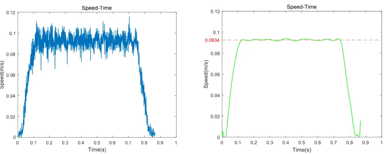
Figure 4. Movement speed curve of the motion control platform: (A) Initial speed curve; (B) After processing speed curve.
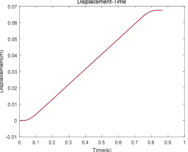
The author used black card M4 camera high frame rate (1000fps) to record the motion video of the motion device of the PCB optical automatic detection and control platform, and tested and tested the actual video image using the above moving target mark point detection method. The displacement fitting curve of the control platform can be obtained as shown in Figure 3, and the speed curve of Figure 4 can be obtained. It can be seen that there are slight fluctuations in the speed curve, but the fluctuation range is small and the overall speed tends to remain stable. It can be seen that the author's PCB optical automatic detection and control platform meets the requirements of image acquisition and post-image processing.
Summary
The application of machine vision improves the accuracy of moving target detection. Based on the comparison of moving target detection methods, this paper proposes an improved moving target detection algorithm-moving target marking point detection method. This algorithm is compared with the traditional algorithm. In comparison, the speed of the moving target can be detected more accurately, and the precision of the moving target can be improved at the same time, which provides a strong guarantee for the detection of subsequent moving targets. Based on the results of the PCB auto-optical control platform's motion speed detection, the program can be automatically detected and the speed of the PCB's automatic optical control platform can be automatically detected. The test results show that the algorithm is ideal.
References
[1] Ayman A. Fuzzy logic and optical correlation-based face recognition method for patient monitoring application in home video surveillance [J]. Optical Engineering, 2011, 50(6): 069801. [2] Merkel M., Boltz M., Koenig M. Surveillance Module for a Video Surveillance System, Method for Monitoring the State of a Surveillance Region, and Computer Program [J]. 2011.
[3] Silvén O., Virtanen I., Westman T., et al. A Design Data-Based Visual Inspection System for Printed Wiring [C] Advances in Machine Vision. Springer-Verlag New York, Inc. 1988: 192-212.. [4] Ying Ren, Chin-Seng Chua, Yeong -Khing Ho. Machine Vision and Applications [J]. 2003, 332-343.