2018 International Conference on Computer, Communication and Network Technology (CCNT 2018) ISBN: 978-1-60595-561-2
FIR Multiphase Decimation Filtering Method Based on Base 2 FFT
Te-liang WANG*, Jun-gang YANG and Yu MO
School of Electrical Science, National University of Defense Technology, Changsha 410073, China *Corresponding author
Keywords: Data compression, Base 2 FFT, FIR, Multiphase decimation filter.
Abstract. It is very important to improve the data throughput of decimation filter for radar systems with large amount of data and high requirement of real-time imaging. On the basis of the analysis of the traditional Finite Impulse Response (FIR) multiphase decimation filtering method, combined with Field Programmable Gate Array (FPGA) , we put forward FIR multiphase decimation filtering method based on base 2 Fast Fourier Transform(FFT). In this paper, the mathematical model of base 2 FFT for FIR multiphase decimation filter is studied, and the hardware structure of multiphase decimation filtering method based on base 2 FFT is presented. The simulation results show that the proposed method can effectively preprocess the echo data of radar system and improve the real-time performance.
Introduction
According to Nyquist theorem, the sample rate of a discrete-time signal must be greater than or equal to twice its bandwidth, otherwise further reducing the sample rate will cause the spectrum aliasing. Therefore, we usually use a low-pass filter to reduce the signal bandwidth before reducing the signal sample rate. As shown in Fig. 1 is a typical structure of decimation filter, composed of a low-pass filter and a sampler. The operating mode is to filter the data first and then sample it.
Low-pass Filter
z
H
Sampler
K
Input Output
Figure 1. Typical structure of decimation filter.
The basic of typical decimation filter is simple, but when the signal has the characteristic of high frequency, the low pass filter needs to deal with a large amount of data. Also, most of the data, processed by a low-pass filter, will be abandoned after being sampled. This is not only a great pressure to hardware implementation but also a waste of hardware resources. Therefore, if we can sample the signal first and then filter it, we can save the hardware resources, reduce the calculation amount and increase operation velocity.
To sample the data first and then filter it, we have to devise the parallel processing structure of FIR at first. The common algorithms to realize the parallel processing structure of FIR include Iterated Short Convolution Algorithm (ISCA) [1,2], Fast FIR Algorithm(FFA) [3]and improved algorithms based on FFA[4-9]. In addition, Sinha P et al. designed a digital signal processing basic unit to construct parallel FIR filter [10], and Conway et al. implemented the parallel FIR filter by using the theory of number theoretic transform [11]. These methods are low-complexity and easy to realize, but do not give full play to the advantages of abundant hardware resources of the 7th generation FPGA released by Xilinx in 2012. And in recent years, with the application of radar systems to security check and other fields, the requirement of real-time data processing is getting higher. Therefore, it is necessary to study a FIR multiphase decimation filtering method with high real-time performance.
Basics of Traditional FIR Multiphase Decimation Filter
For the sequence x n
( )
with N points, the order of the FIR filter is N−1, and its FIR filter outputcan be expressed in Z domain as
( )
( ) ( )
( )
( )
1 1 0 0 N N n n n nY z X z H z x n z h n z
− −
− −
= =
= =
∑
∑
(1)If the decimation factor is K, then K-phase decomposition can be applied to X z
( )
and H z( )
.( )
( )
( )
(
)
( )( )
( )
( )
(
)
( )
(
)
( )(
)
( )(
)
(
)
( )(
)
( )(
)
( )(
)
( )
( )
( )
(
)
( )
(
)
(
)
(
)
(
)
(
)
(
)
(
)
( ) 1 1 1 1 11 1 1
1
1
0 1 1
0
1 1 1
1 1 1
0
1 1 1
1 1 1
N
K Kl
K Kl
K K K K Kl
K Kl
K Kl
K
K Kl
X z x x z x N z
x x K z x Kl z
x z x K z x Kl z
x K z x K K z x K Kl z
x x K z x Kl z
x x K z x Kl z z
x K x K K z x K Kl z z
− − − − − − + − + − − − − − + − − + − − − − − − − − − = + + + − = + + + + + + + + + + + − + − + + + − + = + + + + + + + + + + + − + − + + + − + =
( )
( )
( )( )
( ) 1 10 1 1
1 1
0 1 1
K
K K K
K K
K
X z z X z z X z
X z X z X
− − − − − − − − + + = + + (2)
( )
1 ( 1)0 1 1
K K
H z H z− H z− − H
−
= + ++ (3)
Where K≤N, and N can be divisible by K, i.e. N l K = . If
N can’t be divisible by K, then
we can remove the excess items in the Eq. 2 and Eq. 3. Substituting Eq. 2 and Eq. 3, we can write Eq. 1 as,
( )
(
)
(
)
(
)
( )( )
( )
( )
( ) ( )0 0 1 1 1 1
1
1 0 0 1 1 2 2 1
1
1 0 2 1 0 1
1 1
0 1 1
1 1
0 1 1
K K
K K
K K
K K
K
K K K
K
K K K
K K
K
Y z H X z H X z H X
H X H X z H X z H X z
H X H X H X z
Y z Y z z Y z z
Y z Y z Y
− − − − − − − − − − − − − − − − − − − − − − = + + + + + + + + + + = + + + = + + + (4)
The matrix form of Eq. 4 is as following equation
0 0 1 1 0
1 1 0 2 1
1 1 2 0 1
K K
K
K
K K K K
Y H z H z H X
Y H H z H X
Y H H H X
Since the decimation factor is K, for every K output data of the filter, we only use one of the data, and the other K-1 data are discarded. Eq. 5 can be composed as
[
] [
]
0
1
1 1 2 0
1
K K K
K
X X
Y H H H
X − − − − = (6)
Comparing Eq. 5 with Eq. 6, the method which we sample the signal first and then filter it by FIR
multiphase decimation filter can reduce the calculation amount to 1
K of the original with the typical
method.
FIR Multiphase Decimation Filtering method Based on Base 2 FFT
The Design Idea
The FIR filter output of input data x n
( )
, in frequency domain, is given by the following equation:( )
1( )
1( )
( ) ( )
0 0
N N
nk nk
N N
n n
Y k x n W h n W X k H k
− −
= =
=
∑
∑
= (7)By the means of zero padding to sequence x n
( )
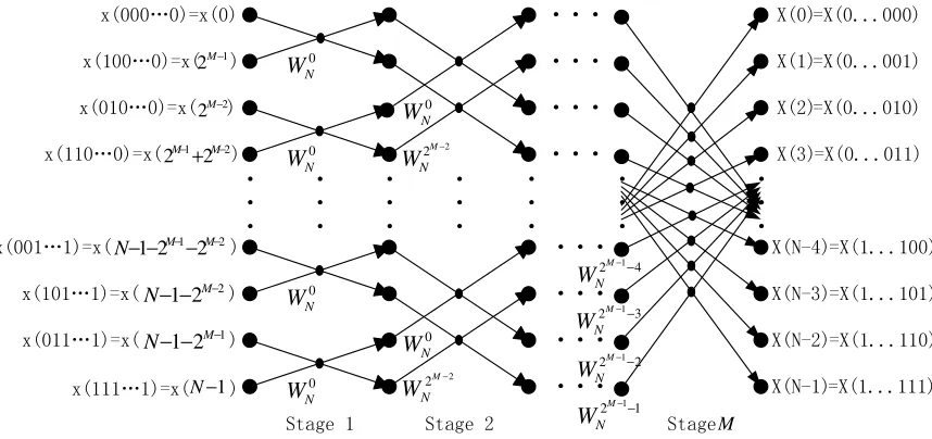
with N points, we can make 2MN = . According to the basics of the base 2 FFT algorithm, the operation flow diagram of the base 2DIT-FFT algorithm is shown in Fig. 2.
x(000…0)=x(0)
x(001…1)=x( ) x(110…0)=x( ) x(010…0)=x( )
x(100…0)=x( )
X(0) X(N-1) X(N-2) X(N-3) X(N-4) X(3) X(2) X(1)
Stage 1 Stage 2 Stage
· · · · · · · · · · · · · · · · · · · · · ··· ··· ··· ··· ··· ··· ··· ··· =X(0...000) =X(0...001) =X(0...010) =X(0...011) =X(1...111) =X(1...110) =X(1...101) =X(1...100) 1
2M−
2 2M−
2 1
2 2− −
+M M
2 1 2
2 1− −− −
− M M
N
x(101…1)=x( )2
2 1− − − M
N
x(011…1)=x( )1
2 1− − − M
N
x(111…1)=x( )N−1
0 N W 0 N W 0 N W 0 N W 0 N W 2
2M− N W 0 N W 2
2M− N
W
[image:3.612.92.521.393.595.2]1 2M−1− N W 4 2 1 − − M N W 3 2M−1− N W 2 2 1 − − M N W M
Figure 2. The operation flow diagram of the base 2 DIT-FFT algorithm.
k N
W is a rotation factor. As shown in Fig. 2, the base 2 DIT-FFT algorithm has the following
characteristics: The order of input sequence x n
( )
and output sequence X k( )
is followed by theprinciple of reversing bit code. The sequence with N points while N =2M can be divided into M
stages. And there are 2
N
butterfly processing elements at each stage. Each butterfly operation
consists of one complex multiplication, one complex addition and one complex subtraction. The interval between two data points of the same butterfly operation in stage m is 1
1
2m− different expressions of rotation factor in stage m, where
1, 2
m= M . When the algorithm is implemented in hardware, the input data and output data of the same butterfly processing element can share the memory cell.
Therefore, we can transform the input data of the filter into frequency domain by using the base 2 DIT-FFT, and remove the invalid operations of the base 2 FFT to complete the decimation of the input data. Then we can complete the FIR filtering of the base 2 FFT output data in frequency domain to realize the FIR multiphase decimation filtering.
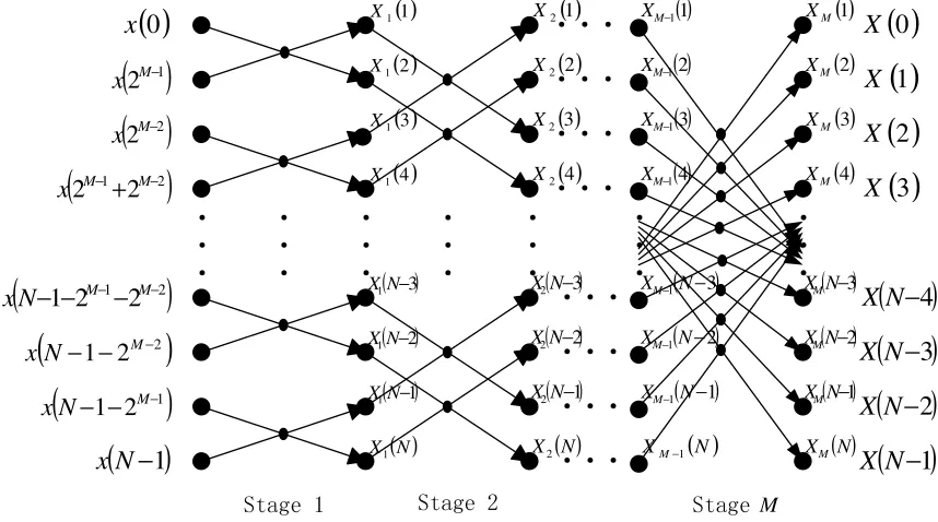
The Mathematical Model
Based on the above studies, we need to develop a mathematical model that we can remove the invalid operations of the base 2 FFT algorithm. We simplified the operation flow diagram of the base 2DIT-FFT algorithm in Fig. 2 as shown in Fig. 3.
Stage 1 Stage 2 Stage
· · · · · · · · · · · · · · · · · · · · · ··· ··· ··· ··· ··· ··· ··· ···
( )
22M−
x
(
1 2)
2
2M−+ M−
x
(
1 2)
2 2
1− −− −
− M M
N x
(
2)
2
1− −
− M
N x
(
1)
2
1− −
− M
N x
(
N
−
1
)
x
( )1 1
X
( )N X
1 ( 1) 1N−
X
( 2) 1N−
X
( 3) 1N−
X
( )4 1
X
( )3 1
X
( )2 1
X
( )
1 2X
( )
N X2(
1)
2N−
X
(
2)
2N−
X
(
3)
2N−
X
( )
4 2X
( )
3 2X
( )
2 2X
( )
1 1 − M X( )
N XM 1−
(
1)
1 − − N X
M
(
2)
1 − − N XM
(
3)
1 − − N XM
( )
4 1 − M X( )
3 1 − M X( )
2 1 − M X( )
1M X
( )
N XM( )
N−1X M
(
N−2)
XM( )
N−3XM
( )
4M X
( )
3M X
( )
2M X
( )
0
x
( )
12M−
x
( )
0
X
(
N
−
1
)
X
(
N
−
2
)
X
(
N
−
3
)
X
(
N
−
4
)
X
( )
3
X
( )
2
X
( )
1
X
[image:4.612.91.520.229.468.2]M
Figure 3. The simplified operation flow diagram of the base 2 DIT-FFT algorithm.
As we all know, the interval between two data points of the same butterfly operation in stage m is 1
2m− . After further analysis and induction, we can see that if one of the output data of a butterfly
processing element is
( )
mX n , then the other one is shown as
(
)
(
)
(
)
(
)
1 1 1 1 1 1 12 , 1 mod 2
2
1
2 , 1 mod 2
2 m m m m m m m m n
X n n
n
X n n
− − − − − − − + − − − − − −
when i s an even number .
when i s an odd number .
(8)
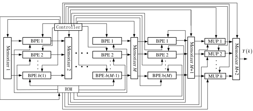
The Hardware Structure
There are 480,000 logical units in the Kintex-7 FPGA which is cost effective. Considering the total requirements of hardware resources for a radar system, we can guarantee the implementation of at least 8,000 butterfly processing elements on the Kintex-7 FPGA.
M
em
o
ri
ze
r 1
BPE 1
BPE 2
BPE b(1)
· · ·
M
em
o
ri
ze
r 2
···
···
BPE 1
BPE 2
BPE b(M-1)
· · ·
M
em
o
ri
ze
r
M
Controller
ROM
BPE 1
BPE 2
BPE b(M)
· · ·
MUP 1 MUP 2
MUP h
· · ·
M
em
o
ri
ze
r
M
+
2
( )
Y k
M
em
o
ri
ze
r
M
+
1
Figure 4. Array processing structure of hardware.
The ROM stores the frequency response functions
( )
H k of the filter and the rotation factors k N W .
BPE refers to butterfly processing element. MUP refers to multiplier. And b m
( )
refers to thenumber of butterfly processing elements at stage m. In array processing structure of hardware, all
the operations are processed in parallel.
If the required amount of butterfly operations was more than 8000, we can use parallel iteration processing structure of hardware, as shown in Fig.5, to realize FIR multiphase decimation filtering.
M
em
o
ri
ze
r 1
BPE 1
BPE 2
BPE b
· · ·
M
em
o
ri
ze
r 2
Controller
ROM
MUP 1
MUP 2
MUP h
· · ·
M
em
o
ri
ze
r 3
( )
Y k
Figure 5. Parallel iteration processing structure of hardware.
In parallel iteration processing structure of hardware, the butterfly operations of the same stage are processed in parallel, and the stages are processed in sequence.
Simulation Experiment and Performance Analysis
Simulation Experiment
[image:5.612.105.512.68.246.2]The method of this paper is simulated by MATLAB, and the simulation parameters are listed in Table 1.
Table 1. Simulation parameters.
Signal Type Noise Type Center Frequency Sampling Frequency
Complex exponential signals White noise 21 [MHz] 81 [MHz]
Number of Data Data-width Decimation Factor Filter Type
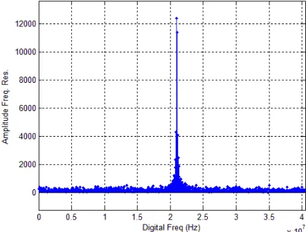
Fig.6 consist the theoretical modulus of the amplitude-frequency response of the simulation data. Fig.7 has the modulus of the amplitude-frequency response of the FIR decimation filter output data. And the modulus of the amplitude-frequency response of the output data of the FIR multiphase decimation filter based on base 2 FFT are shown in Fig.8.
[image:6.612.187.408.547.716.2]Figure 6. Modulus of the amplitude-frequency response of the simulation data.
Figure 7. Modulus of the amplitude-frequency response of the FIR decimation filter output data.
Comparing the simulation results in Fig. 6, Fig. 7 and Fig. 8, we proved that the FIR multiphase decimation filtering method proposed in this paper can effectively process radar echo data.
Performance Analysis
Suppose the time for a butterfly operation is T, the time for a multiplication is t, the number of tap-weight is N and M
N=2 .
All the operations of array processing structure of hardware are processed in parallel and T>t, so
the time for the FIR multiphase decimation filtering of N data is T in theory. In parallel iteration processing structure, the butterfly operations of the same stage are processed in parallel, and the stages are processed in sequence, so the time for the FIR multiphase decimation filtering of N data
is M T⋅ +t.
Conclusion
This paper analyzed the basics of traditional FIR multiphase decimation filter, and put forward the mathematical model of base 2 FFT algorithm applied to FIR multiphase decimation filter. Then we used the principle of multiphase decimation filter to simplify the operation process of the base 2 FFT. Thus we can convert data into frequency domain by the simplified base 2 FFT algorithm to realize the FIR multiphase decimation filter. And we put forward two structures of the hardware implementation of the method. This method is an efficient parallel processing operation, which can make a good use of all the available hardware resources and the parallel processing advantage of FPGA, and can greatly improve the operation speed of FIR decimation filtering.
References
[1] Acha J I. Computational structures for fast implementation of L-path and L-block digital filters [J]. IEEE Transactions on Circuits and Systems, 1989, 36(6): 805-812.
[2] Cheng C and Parhi K K. Hardware efficient fast parallel FIR filter structures based on iterated short convolution[J]. IEEE Transactions on Circuits and Systems I: Regular Papers, 2004, 51(8): 1492-1500.
[3] Parker D A and Parhi K K. Low-area/power parallel FIR digital filter implementations[J]. Journal of VLSI Signal Processing Systems for Signal, Image and Video Technology, 1997, 17(1): 75-92.
[4] Tsao Y C and Choi K. Hardware-efficient parallel FIR digital filter structures for symmetric convolutions[C]. Proceedings of IEEE International Symposium on Circuits and Systems, Riode Janeiro, 2011: 2301-2304.
[5] Tsao Y C and Choi K. Hardware-efficient VLSI implementation for 3-parallel linear-phase FIR digital filter of odd length[C]. Proceedings of IEEE International Symposium on Circuits and Systems (ISCAS), Seoul, 2012: 998-1001.
[6] Liu Z, Ye F, and Ren J. Low-cost parallel FIR digital filter structures utilizing the coefficient symmetry[C]. IEEE 11th International Conference on Solid-State and Integrated Circuit Technology (ICSICT), Xi’an, 2012: 1-3.
[8] Tsao Y C and Choi K. Area-efficient parallel FIR digital filter structures for symmetric convolutions based on fast FIR algorithm [J]. IEEE Transactions on Very Large Scale Integration (VLSI) Systems, 2012, 20(2): 366-371.
[9] Selvakumar J, Narendran S, and Bhaskar V. FPGA based efficient fast FIR algorithm for higher order digital FIR filter[C]. International Symposium on Electronic System Design (ISED), Kolkata, 2012: 43-47.
[10] Sinha P, Sinha A, Basu D. A novel architecture of a re-configurable parallel DSP processor[C]. The 3rd International IEEE NEWCAS Conference, 2005, 71-74.